Introduction
In general, copper possesses many outstanding properties, such as excellent electrical and thermal conductivities, high ductility, and ease of manufacture [Reference Wu, Zhang, Zhang, Zhang and Dong1]. Thus, Cu alloys are regarded as lead frame materials for integrated circuits, casting molds, and crystallizers in continuous casting [Reference Wong, Kwok, Man and Cheng2] and important engineering materials such as electric contacts and commutators [Reference Wang, Ren, Li, Zhang, Sercombe and Yang3]. Nevertheless, it is worth noting that the mechanical properties of Cu alloys, such as low hardness and low wear resistance, do not meet the need of many practical applications. Surface coating is an effective route to overcome the shortcomings of copper components and provides a longer service life of coatings at reduced total cost. There are many ways to improve the mechanical properties of copper, including electroplating [Reference Wang, Ren, Li, Zhang, Sercombe and Yang3], thermal spraying [Reference Guilemany, Nutting, Sobolev, Dong, De Pace, Calero and Fernandez4], and infiltration techniques. Among them, thermal spraying is a highly effective approach for coating preparation. Hsu et al. studied the oxidation resistance of Ni0.2Co0.6Fe0.2CrSi0.2AlTi0.2 HEAs coating through thermal spraying [Reference Hsu, Murakami, Yeh, Yeh and Shimoda5]. However, the thermal spraying is unsatisfactory on metallurgical bonding. Laser cladding is one of the most efficient and economical ways for coating preparation, owing to the high cooling rates (103–108 K/s) which produces metastable phases by exceeding the solid-solubility limit beyond the equilibrium phase diagram with an excellent metallurgical bond to the substrate [Reference Yan, Zhang, Yu, Lu, Yang and Li6]. Thus, laser cladding has many advantages, such as high speed of heating and cooling [Reference Kovalev, Bedenko and Zaitsev7], strong adhesion with the substrate, small heat-affected zone, little change of shape, and thickness of coatings [Reference De Oliveira, Ocelík and De Hosson8]. Thus, laser cladding can cause an effect of solute trapping, which helps to avoid composition segregation [Reference Wu, Jiang, Jiang, Pan, Cao, Deng, Wang and Li9]. Wissenbach et al. studied the effects of processing parameters on the microstructure of Ti45Al5Nb0.5Si-based alloy [Reference Dutta, Katharina, Wissenbach, Höche, Blawert and Weisheit10]. Therefore, laser cladding has wide application prospects, such as surface coatings, near-net-shaped component manufacturing, and part services [Reference Dinda, Dasgupta and Mazumder11].
At present, the study and application of high-entropy alloys (HEAs) are receiving widespread attention in academic and engineering fields. At the beginning, HEAs are designed containing at least five principal elements with contents ranging from 5 to 35 at.%. Then, HEAs were defined as alloys with multiple principal elements in equimolar or near equimolar ratios. Recently, Miraclea et al. [Reference Miraclea and Senkov12] proposed that general definition of HEAs is composed of four elements and the entropy is greater than 1.5R. A series of recent studies have revealed that the HEA coating possesses excellent oxidation [Reference Lee and Lu13, Reference Li, Niu, Yuan, Cao, Chen and Zhou14], corrosion resistance [Reference Qiu, Zhang, He and Liu15, Reference Zhang, Zhang, Yan, Zhang, Wang, Song and Shi16], high strength and hardness [Reference Wu, Lin, Ye, Chen, Huang and Chen17], good thermal stability [Reference Huang, Zhang, Shen and Vilar18], and high wear resistance [Reference Niu, Li, Yuan, Zhu, Chen, Wang and Huang19] compared with conventional Fe, Ni, Co-based alloy coatings. Thus, HEA coatings have promising application prospects in many industrial fields due to their desirable properties. The microhardness of FeNiCoSiCrAlTi HEA coating prepared by laser cladding reaches 780 HV0.5, which is much higher than most of the HEAs prepared by other methods [Reference Chen, Shi and Yang20]. Meanwhile, nonequiatomic Fe80−xMnxCo10Cr10 HEA exhibits comprehensive strength–ductility performance, which is a typical dual-phase HEA, owing to partial martensitic transfer of the face-centered cubic (FCC) to the hexagonal close-packed (HCP) phase upon cooling from the high-temperature single-phase region [Reference Li, Wang and Wu21]. However, the FeMnCoCr HEAs suffer from relatively lower hardness and higher friction coefficients. Cu–Cr alloys possess excellent thermal conductivity [>600 W/(m K)] [Reference Weber and Tavangar22]. However, HEA is a disordered solid solution. Different elements in the disordered solid solution alloy can sit randomly in the crystal lattice, giving rise to the extreme disturbance of local atomic, electronic, and lattice structures. Xia et al. [Reference Xia, Gao, Yang, Liaw and Zhang23] pointed out that the extreme disorder in HEAs decreases the mean free path of energy carriers. Therefore, HEAs can greatly reduce the thermal conductivity. Fan et al. [Reference Fan, Wang and Wu24] studied the thermoelectric properties of the BiSbTe1.5Se1.5 HEA, and the lattice thermal conductivity of this HEA is quite low [0.47 W/(m K) at 400 K]. Although the thermal conductivity of HEAs is lower compared with Cu substrate, the HEA only acts as coating, which has no apparent influence on the cooling ability of Cu continuous casting mold; moreover, the high-temperature stability of HEAs is excellent.
To further improve wear resistance, reinforcement phases were considered to be incorporated [Reference Zhang, Zhang, Yan, Zhang, Wang, Song and Shi16]. The introduction of ceramics as reinforcement particles into the metal matrix allows for better mechanical performance [Reference Chen, Shi and Yang20]. Among these, TiC particle, as a refractory compound, possesses high thermal stability during the metallurgy process with high hardness and outstanding wear resistance; hence, it is used as a promising reinforcement particle [Reference Zhu, Dong, Wang, Huang, Li and Xie25]. CaF2 is an effectively and widely used solid lubricant of many high-temperature composite materials, which has unique physical, chemical, and microstructural effects on the tribological contact of working surfaces such as a lamellar structure with low shear strength, enabling tribochemical reactions and preventing adhesion [Reference Liu, Liu, Zhang and Guo26, Reference Xiang, Liu, Ren, Luo, Shi, Chen, Shi and Wu27]. It is easy to shear on the base plane of a hexagonal crystal structure, which is the mechanism of prominent lubrication performance [Reference Yan, Zhang, Zhang, Yu, Li, Xu and Lu28]. The WC-Co/BaF2/CaF2 composite coating containing 10 wt% Cu was found to have excellent frictional and wear performance [Reference Yuan, Zhu, Ji, Zheng, Ruan, Niu, Liu and Zeng29]. TiC-particle-reinforced Inconel 625 coatings obtained through laser cladding gained an average microhardness of 330 HV, revealing a sharp increase compared with pure Inconel 625 coatings (220 HV). The addition of TiC particles results in a hardness improvement of ASIS 316L stainless steel [Reference Xu, Mi, Xiong, Jiang, Shao and Wang30]. Although the FeMnCoCr HEA possesses good strength and plasticity [Reference Li and Tasan31], the effects of TiC and CaF2 addition on FeMnCoCr coating have never been reported. In this paper, the pure FeMnCoCr, FeMnCoCr/TiC, and FeMnCoCr/TiC/CaF2 self-lubricating coatings on copper were produced using laser cladding. This work aims to provide a novel way with respect to manufacturing self-lubricating coatings on copper for continuous casting mold, which possesses good antiwear and friction reducing properties. Therefore, it has great potential in the metallurgical industry.
Results and discussion
Phase identification
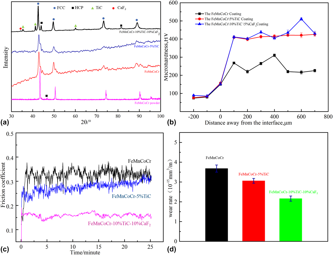
Figure 1(a) presents the X-ray diffraction (XRD) pattern of the FeMnCoCr-based coating. It can be seen that the FeMnCoCr-based coatings are mainly composed of FCC and HCP phases. Only the FeMnCoCr/TiC/CaF2 coating has the apparent diffraction peak of the TiC phase. It is because that the TiC content among the FeMnCoCr/TiC coating is low. Obviously, the diffraction peak of CaF2 in the FeMnCoCr/TiC/CaF2 coating is detectable, but the diffraction intensity is relatively lower, owing to the relatively smaller weight fraction of CaF2. The diffraction peak of HEAs alloys coating is apparently broader than the FeMnCoCr powder and shifts to the left [Reference Shang, Axinte, Sun, Li, Li, Du, Qiao and Wang32]. Grain refinement is a primary reason leading to a broad peak proved by the microstructure of the FeMnCoCr HEA coating (Figs. 2–4). The lattice parameters of FCC and HCP are approximately 3.63 Å and a = b = 2.66 Å, c = 4.33 Å, respectively. In the following experiments, including scanning electron microscopy (SEM), transmission electron microscope (TEM) and wear tests, the FeMnCoCr HEA coatings are all prepared with a laser power of 4000 W.
XRD patterns, microhardness, and wear performance of the FeMnCoCr/TiC/CaF2 self-lubricating HEA coatings: XRD pattern (a); microhardness (b); friction coefficient (c); wear rate (d).

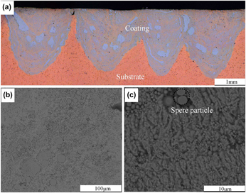
Microstructure of the laser-cladded FeMnCoCr self-lubricating HEA coating: metallographic image (a); SEM photographs (b and c).

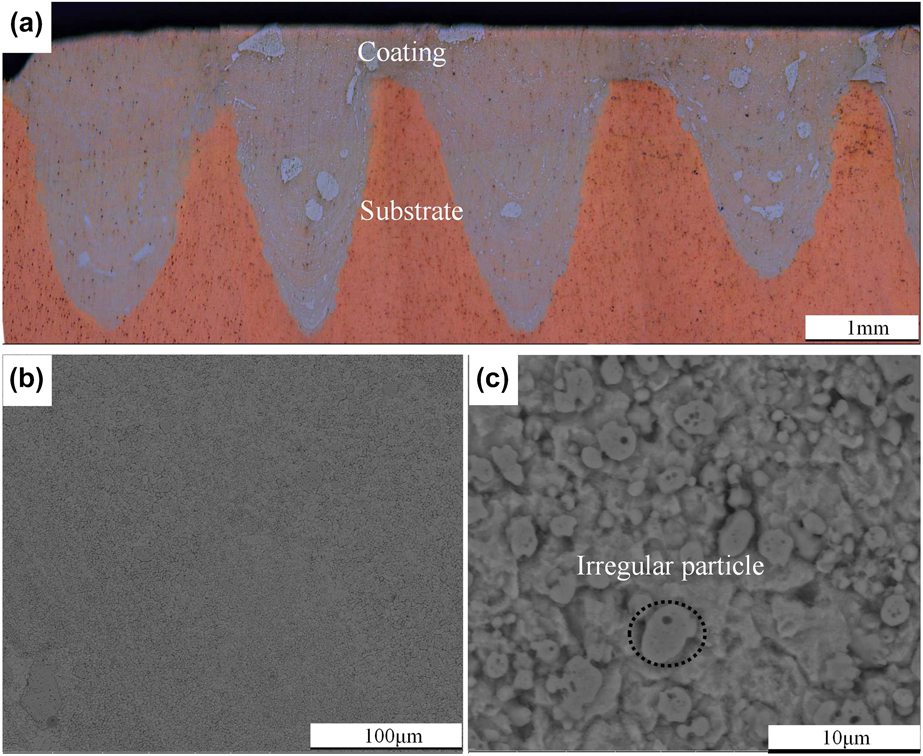
Microstructure of the laser-cladded FeMnCoCr/TiC self-lubricating HEA coating: metallographic image (a); SEM photographs (b and c).

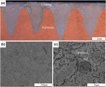
Microstructure of the laser-cladded FeMnCoCr/TiC/CaF2 self-lubricating HEA coating: metallographic image (a); SEM photographs (b and c).

Microstructures
Figures 2–4 show integral microstructures from cross sections of the HEA composite coatings with different compositions. The depth of molten pool becomes deeper with the addition of TiC. During the laser cladding process, mass transfer and the strong convection effect result in the macroscopic material transfer on the matrix and HEA composite coating. Because the temperature rapidly exceeds the melting point, the evaporation flow of the metal is formed under the laser beams and the metal vapor has a powerful hedge function, which makes the metal liquid on the bottom gather on both sides. Therefore, the matrix at the bottom sequentially suffered from the laser beam bombardment, which can alter the melting pools’ sizes. The surface tension increases [Reference Weber and Tavangar22] in metal liquid with the addition of TiC and the gravity of TiC which changes the direction of the convection pushes more energy down to the bottom. Unmelted TiC particles also collide with the matrix during laser radiation. So the depth of molten pool becomes deeper with the addition of TiC. Also, it can be seen that the HEA mixed well with the Cu matrix at the molten pool, because the molten pool has a strong convection effect during the interaction process between laser and molten pool. The filament line, characterized by the dark HEA particle line, is visible at the microstructure. Thus, the molten pool is composed of HEA composites and Cu alloy. During laser cladding process, the laser energy in laser beam follows the Gaussian distribution, and the temperature in the center is higher than the verge of the laser spot. The laser power of fiber laser 4000 W was used in the present cladding experiment; the laser density was dramatically high and the keyhole phenomenon occurred [Reference Salminen and Fellman33, Reference Dai and Gu34], producing a deep penetration welding pool with a high depth-to-width ratio. Simultaneously, the lapping ratio between welding pools was relatively low, so the HEA composite coatings show a jagged shape. From Fig. 2(b), it can be seen that the microstructure of the pure HEA coating mainly consists of spherical grains. The HEA particles seem to embed in Cu alloys substrate or be encompassed by Cu alloys. Spherical particles were Fe-rich phases with some Cu elements confirmed by energy dispersive spectrometer (EDS). The Fe-rich phases contains 8.99 at.% Cr, 6.9 at.% Mn, 53.91 at.% Fe, 10.71 at.% Co, and 19.47 at.% Cu. Interestingly, the microstructure of the FeMnCoCr/TiC HEAs coating was relatively uniform compared to the FeMnCoCr coating. The microstrucure of the FeMnCoCr/TiC/CaF2 coating was most even. The FeMnCoCr/TiC and the FeMnCoCr/TiC/CaF2 sufficiently mix with Cu matrix. Unlike conventional coating covering on matrix, the FeMnCoCr/TiC and the FeMnCoCr/TiC/CaF2 HEAs mix with Cu–Zr–Cr matrix adequately. It is different from other Co-based and Ni-based HEA coating. The degree of mixture between HEA alloys and Cu alloys determines the microstructure. The mix between composite coating and Cu-base matrix can be understood from heat and mass transfer. Heat transfer in the molten pool is a very intricate process, including solid–liquid–vapor three-phase transformations [Reference Tang, Pang, Chen, Suo and Zhou35]. During laser cladding, the molten pools were divided into two regions at first. The region in the center of laser spot possesses relatively high temperatures while another region in the edge of laser spot has relatively lower temperatures. There exists a huge temperature gradient, so fluid flow is very fierce in the molten pools. The fluid flow in molten pools results in a unique microstructure. Meanwhile, high-temperature region and low-temperature region varied with time.
As shown in Fig. 3(b), spherical particles become more and more irregular with the addition of the TiC. When the TiC and CaF2 are added, dendrites form in the FeMnCoCr/TiC/CaF2 coating. The composition of molten pool is more complicated after the addition of TiC and CaF2, which will increase the possibility of composition segregation. The depth of molten pool becomes deeper, and the powder system more easily absorbs the energy of the laser beams after the addition of TiC and CaF2. It leads to an increase in temperature gradient from the center zone to the marginal zone of the molten pool. The two reasons, composition segregation and high temperature gradient, may result in dendrites that form in FeMnCoCr/TiC/CaF2 coating when TiC&CaF2 are added. Under the impact of the laser beam heating, the temperature increases sharply to 3000 °C in just 0.5 s. Without doubt, the HEAs composite coating and matrix were molten in this process. Also, the cooling process of a point was extremely transient. The solidification process consists of two stages. The first stage is that temperature rapidly decreases to the melting point of the FeMnCoCr HEA composite alloys in 0.5 s. At this time, the cooling rate is really fast. The second stage is that the melting point decreases to room temperature, and the cooling rate is relatively low compared with the first stage [Reference Chen, Pang and Shao36]. In general, the cooling rate during the laser cladding is high compared with conventional casting. It is in favor of refining the grain and improving material performance. ImageJ is applied to estimate the grain size, which is approximately 2.768, 1.225, and 1.200 μm, respectively.
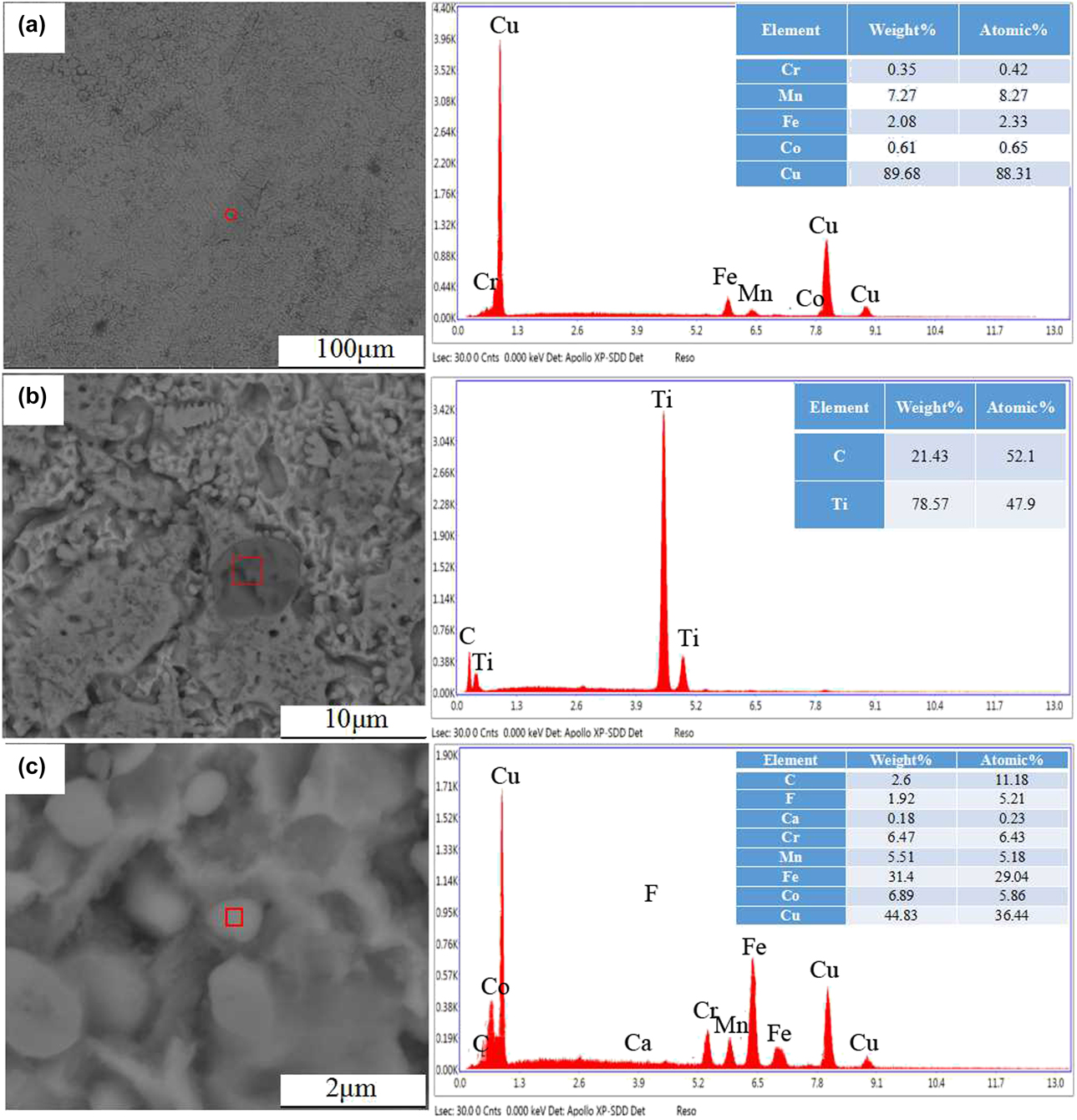
Selected regions of EDS analysis is shown in Fig. 5. The large irregular particles of FeMnCoCr HEAs contain 88 at.% Cu as shown in Fig. 5(a). Nanocrystalline FeMnCoCr/TiC/CaF2 HEAs coating can also be found in Fig. 5(c). The ratio of Cu in the FeMnCoCr/TiC/CaF2 HEA coating is four times higher than the FeMnCoCr. Some large nearly spherical particles can also be found in the microstructure, which is identified as TiC by EDS analysis [Fig. 5(b)] combined with XRD diffraction peaks Fig. 1(a). The TiC particles are nearly spherical and possess a grain size of 8–10 μm, which is larger than other grains. During the laser cladding, large number of dispersing TiC particles appeared when the molten pool was firstly formed. Due to the high melting point of TiC powder (3067 °C), these dispersed TiC particles were covered and moved with melted FeMnCoCr liquid during solidification, forming the final particle distribution. Thus, the distribution of TiC is relatively uniform.
Selected regions of EDS analysis of the FeMnCoCr/TiC/CaF2 coating: the FeMnCoCr coating (a); the FeMnCoCr/TiC/CaF2 coating (b and c).

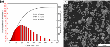
Size distribution and SEM photographs of FeMnCoCr HEA powder: size distribution (a); SEM photographs (b).

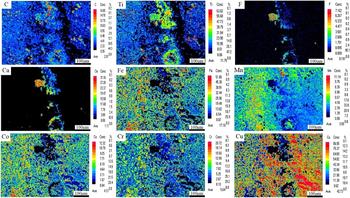
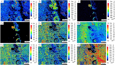
The electron probe microanalyzer (EPMA) mapping of HEA composites coating from the top view is shown in Fig. 7. The results show that the distributions of F and Ca elements matched well in the middle of Fig. 7, although accompanied with agglomeration in the red regions. So the existence of CaF2 is confirmed in HEA composite coating, which is consistent with the results of XRD. On the whole, Fe, Mn, Co, Cr, Ti, and C elements were distributed uniformly in the HEA composite coating. It is worth noting that the content of Cu element is 42.73%, which is substantial high.
EPMA mapping of the FeMnCoCr/TiC/CaF2 coating.

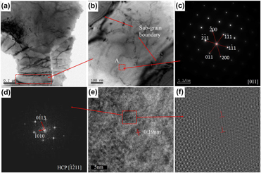
To further observe the microstructure of HEA/TiC/CaF2, TEM coupled with selected area electron diffraction (SAED) patterns and HRTEM was used, as shown in Fig. 8. From the bright-field TEM images [Figs. 8(a) and 8(b)], the subgrain boundaries are distinguished and the size of subgrain is approximately in the range of 300–400 nm. The corresponding SAED pattern of point A is shown in Fig. 8(c) and the [011] zone axis diffraction pattern displays the FCC structure. Meanwhile, the lattice parameter of the FCC phase measured by SAED is 3.67 Å, which is in accordance with the result of XRD characterization. The image of HRTEM is shown in Fig. 8(e), from which it can be seen that interatomic spacing is 1.09 Å. Electron diffraction pattern was obtained by means of Fourier transformation as shown in Fig. 8(d). It is interesting that there other diffraction spots in contrast to Fig. 8(c). After the analysis, the diffraction confirmed the existence of solid solution with the HCP structure, corresponding to the  $\left[ {\bar{1}2\bar{1}1} \right]$ zone axis. The enlarged image of HRTEM is also presented through inverse Fourier transformation, and edge dislocations can be found in Fig. 8(e).
Bright-field TEM images of the laser-cladded FeMnCoCr/TiC/CaF2 HEA coating (a, b); SAED patterns of A region (c); SAED patterns of B region through FFT (d); HRTEM patterns of point A (e); HRTEM patterns of B region (f).

Microhardness
Figure 1(b) shows the microhardness distribution from the top surface to the interface of the coating. The mean microhardness of the FeMnCoCr, FeMnCoCr/TiC, and the FeMnCoCr/TiC/CaF2 coating is higher than the copper substrate with a value of about 80 HV. Without doubt, the microhardness value of the FeMnCoCr/TiC coating is the largest among these three types of coatings. This demonstrates that the TiC particles play a great role in increasing the microhardness. The figure shows that the average microhardness value of the FeMnCoCr/TiC/CaF2 coating is in the range of 398.6–510.2 HV with a thickness of more than 600 μm. Nevertheless, it was also noticed that its microhardness values fluctuate between greater extremes. This is because the large TiC particles and small ones are not uniformly distributed, while the FeMnCoCr/TiC coating is relatively uniformly distributed, which demonstrates that it possesses homogeneous mechanical properties. However, the microhardness of the FeMnCoCr/TiC/CaF2 coating is close to the microhardness of the FeMnCoCr/TiC coating. On the basis of the mixture principle of composites, the hardness of the material decreased with the addition of soft phase in a hard substrate [Reference Yakovlev, Bertrand and Smurov37, Reference Song, Wang, Yan, Zhang, Zhang, Cai, Wei and Shi38].
Wear resistance of the FeMnCoCr-based coating
A ball made of Q325 steel with a diameter of 2 mm was chosen as the wear tool counter against the coating. The tests were performed at a load of 15 N for 25 min with a linear velocity of 392.5 mm/s. Figure 1(c) represents the variation in friction coefficients for Cu substrate and FeMnCoCr-based coating as a function of wear test time. As the testing time increases, the friction coefficients of the tested samples gradually reach a constant value during the whole period of the wear test. The mean friction coefficients of the FeMnCoCr, FeMnCoCr/TiC, and FeMnCoCr/TiC/CaF2 coating were measured as 0.35, 0.27, and 0.16, respectively. The FeMnCoCr/TiC and FeMnCoCr/TiC/CaF2 coatings show 22 and 54% decrease compared with the pure FeMnCoCr coating, indicating that the wear resistance is prominently enhanced with the addition of TiC and CaF2. This is consistent with the previous results that laser cladding metal matrix composite coatings with the addition of CaF2 show lower friction coefficients than the original substrate under dry sliding wear conditions [Reference Yan, Zhang, Yu, Lu, Yang and Li6]. The low friction coefficient of 0.16 of the present work is close to the friction coefficient of 0.19 of laser cladded Co-based alloy/20%TiC/10%CaF2 coating [Reference Yan, Zhang, Zhang, Yu, Li, Xu and Lu28]. But the contents of 10% TiC and 10% CaF2 in the FeMnCoCr/TiC/CaF2 are lower than Co-based 20%TiC/10%CaF2. So the wear resistance of the FeMnCoCr/TiC/CaF2 coating can be further improved through increasing the contents of the reinforcing phases. Certainly, the addition of CaF2 can improve the wear resistance of the coating and reduce the friction coefficient to some extent, which is attributed to the shearing along the basal plane of the hexagonal crystalline structures of CaF2. During the test process, under the effect of friction heat and friction force, solid lubricant is precipitated out on the friction surface. A large number of solid lubricants are precipitated out and then dragged on the friction surface, and a self-lubricating film is formed on the friction surface, reducing the abrasion significantly. Meanwhile, the addition of TiC makes the hardness of the coating reach a high level, while the hardness is beneficial for the decrease in the friction coefficient.
To further identify the wear resistance of tested samples, the wear rate and the morphology of worn surface are presented. The derivation process of the wear rate Q s is described in detail [Reference Attar, Prashanth, Chaubey, Calin, Zhang, Scudino and Eckert39]:
 $${Q_{\rm{s}}} = {{{V_{\rm{s}}}} / {{L_{\rm{s}}}\quad ,}}$$
where Q s represents the wear rate, V s the volume loss, and L s the sliding distance.
The relation of volume loss V s Δm is presented as follows:
 $${V_{\rm{s}}} = {{\Delta m} / {\rho \quad ,}}$$
where Δm stands for the mass loss after the wear tests and ρ the density of the alloy. The sliding distance L s can be characterized by the following equation:
 $${L_{\rm{s}}} = 2\pi r{V_{\rm{r}}}t\quad .$$
In this equation, r represents the radius of the wear track, V r the sliding angular velocity, and t the wear testing time. In this paper, the radius of the wear track r is 2.5 mm, the wear experiment time t is 25 min, and the sliding angular velocity V r is 1500 r/min. Therefore, L s is calculated to be 588.75 m. The value of ρ is 7.754, 7.6136, and 7.0131 g/cm3, respectively. The value of Δm is 1.68, 1.37, and 0.89 mg, respectively. The value of Q s is 3.68 × 10⁻¹⁵, 3.06 × 10⁻¹⁵, and 2.16 × 10⁻¹⁵ mm3/m for the FeMnCoCr coating, FeMnCoCr/TiC coating and FeMnCoCr/TiC/CaF2 coating, respectively. Consequently, the wear resistance of the FeMnCoCr/TiC/CaF2 coating is excellent. As shown in Fig. 1(d), the FeMnCoCr/TiC coating and FeMnCoCr/TiC/CaF2 coating show lower wear loss than the FeMnCoCr coating, which further confirms that the addition of TiC and CaF2 improves the wear resistance.
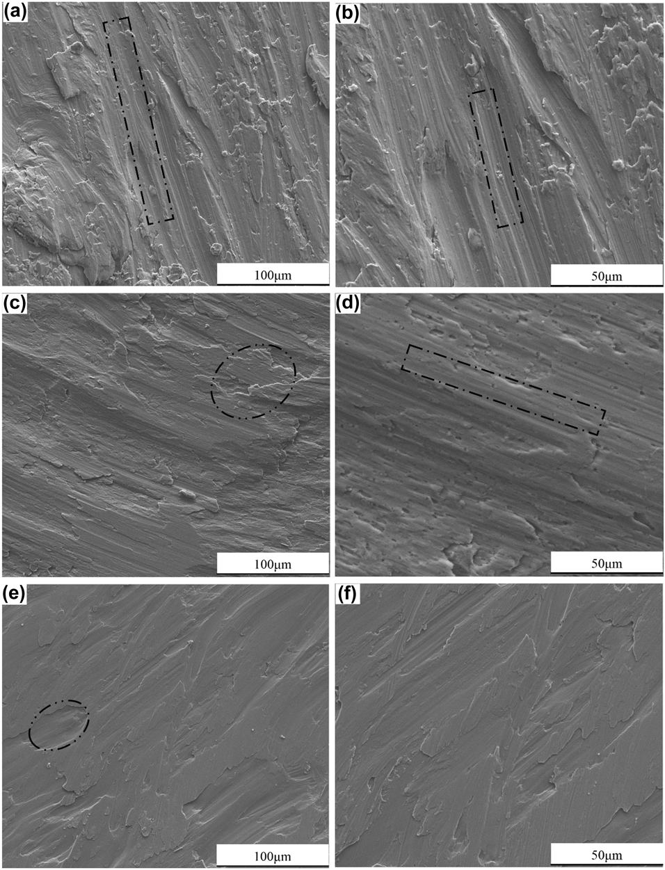
There are apparent chipping pits and parallel grooves observed on the worn surfaces of the three coatings (Fig. 9); thus, it can be found that the wear mechanism of the FeMnCoCr coating is mainly abrasive wear mechanism. As shown in Fig. 9, the pure FeMnCoCr coating tend to suffer from the more intense plastic deformation compared with the FeMnCoCr/TiC and FeMnCoCr/TiC/CaF2 coatings with second reinforcement phase under the combined effect of normal and tangential force. Meanwhile, cracks and worn grooves also become deeper on the worn surfaces. Under the load of 15 N, there are sharp abrasion grooves on the wear paths, which are formed in the center of the wear paths, covering almost every part of the wear paths. During this time, the adhesive wear and the abrasive wear are mixed up. Coincidently, the worn surface of the FeMnCoCr/TiC/CaF2 coating is smoother than the other two coatings mentioned above. It is indicated that the FeMnCoCr/TiC/CaF2 coating surface does not suffer from plastic deformation. Generally, the higher the material hardness, the higher the abrasive wear resistance, so the adhesive wear is the main wear mechanism for the FeMnCoCr/TiC/CaF2 coating. Since that the hardness of the FeMnCoCr coating is much lower than the grinding balls (Q325 steel 61 HRC), the coating hardness is the main factor for wear resistance [Reference Huang, Zhang, Vilar and Shen40]. Therefore, the decrease in friction coefficients of the FeMnCoCr/TiC coating and FeMnCoCr/TiC/CaF2 coating is the result of the combined contribution of the transformation of wear mechanism and the second phase reinforcement.
SEM micrographs of wear scars of the laser-cladded HEA coating at room temperature: the FeMnCoCr coating (a, b); the FeMnCoCr/TiC coating (c, d); the FeMnCoCr/TiC/CaF2 coating (e, f).

Conclusions
The pure FeMnCoCr, FeMnCoCr/TiC, and FeMnCoCr/TiC/CaF2 composite coatings were prepared successfully through laser cladding. The results show that FeMnCoCr HEA is mainly composed of FCC and HCP solid-solution phases. The microstructure of the FeMnCoCr HEA coating is mainly composed of spherical particles and nanocrystalline structures, because the HEA particles are almost insoluble in Cu during the laser cladding. Spherical particles become more and more irregular with the addition of TiC. After the addition of TiC and CaF2, the dendrite is presented in the microstructure of the FeMnCoCr/TiC/CaF2 coating. The microstructure of the FeMnCoCr/TiC HEAs coating is relatively uniform compared to the FeMnCoCr coating. The microstrucure of the FeMnCoCr/TiC/CaF2 coating is most even.
The mean microhardnesses of the FeMnCoCr, FeMnCoCr/TiC, and FeMnCoCr/TiC/CaF2 coating are higher than that of the copper substrate (80 HV). Meanwhile, the micro-hardness of the FeMnCoCr/TiC/CaF2 coating (433.3 HV) is the highest among these three types of coatings, followed by the FeMnCoCr/TiC coating (414.9 HV) and the FeMnCoCr coating (246.5 HV).
The mean friction coefficient of the FeMnCoCr, FeMnCoCr/TiC, and FeMnCoCr/TiC/CaF2 coating is 0.35, 0.27, and 0.16, respectively. The value of wear rate is 3.68 × 10⁻¹⁵, 3.06 × 10⁻¹⁵, and 2.16 × 10⁻¹⁵ mm3/m, respectively. From the wear morphologies, the main wear mechanism of the FeMnCoCr coating is abrasive wear while the FeMnCoCr/TiC coating is abrasive and adhesion wear. The wear mechanism of the FeMnCoCr/TiC/CaF2 coating is dominated by adhesive wear.
Materials and experimental details
An as-received Cu–Zr–Cr plate with dimensions of 200 × 50 × 20 mm was selected as the substrate material. The Cu alloys were ground with SiC paper to wipe off surface oxides or contaminants. Then, the substrate was degreased and ultrasonically rinsed in ethanol followed by washing in distilled water and dried in cold air stream. Figure 6 shows the size distribution of the FeMnCrCo HEA powder and the morphology. More than 70% of the powder particles are in the size range of 0–20 μm. Dv10, Dv50, and Dv90 are 4.79, 16.5, and 40.5 μm, respectively. As shown in Fig. 6(b), the shapes of particles are either spherical or irregular. Raw materials (FeMnCrCo powder, TiC, CaF2) powders with high purity (≥99.5%) were mixed with a high-energy planetary ball milling machine to form HEA coatings. The theoretical chemical composition of the three types of FeMnCoCr-based HEA coatings is as follows: 100 wt% FeMnCoCr powder; 95 wt% FeMnCoCr powder, 5 wt% TiC; 80 wt% FeMnCoCr powder, 10 wt% TiC, and 10 wt% CaF2. The milling time was 8 h. During the milling process, the ball milling tank was filled with argon gas to protect the powder from oxidation.
The YLS-4000 fiber laser system with IPG (IPG Photonics Corporation, German) was used to implement laser cladding with a rated power of 4 kW, a power stability plus or minus of 1%, and a wavelength of 1070 nm. The laser cladding parameters are as follows: average laser power of 4000 W, laser spot diameter of 4 mm, scanning speed of 10 mm/s, overlap rate of 50%, and the defocus distance of 30 mm adopting co-axial powder-feed mode. To prevent oxidation again, the working area was filled with shielding gas (high-purity argon) with a flow rate of 18–20 L/min during laser cladding, and all laser-cladded samples were cooled to room temperature in air.
The microstructure of the FeMnCoCr-based coating samples was characterized by an optical microscope coupled with a scanning electron microscope (SEM; Quanta 250 FEG, FEI, Hillsboro, Oregon). The distribution of coating composition was detected by an energy dispersive spectrometer (EDS; X-Max, Oxford instruments Co., Oxford, UK), and the distribution of coating composition was precisely probed by an electron probe microanalyzer (EPMA). Microstructure and selected area electron diffraction (SAED) were also characterized using a Tecnai G2F20 transmission electron microscope (TEM; FEI, Hillsboro, Oregon). The phase composition was characterized by X-ray diffraction (XRD; D/max 2500 Pc, Rigaku, Tokyo, Japan) at a scanning speed of 10°/min, ranging from 20° to 100°, with Cu Kα radiation of 30 Kv and 15 mA. Image analysis software (ImageJ, National Institutes of Health, New York City, NY) was used to handle the SEM images to estimate the crystalline grain size of the HEA coating.
A microhardness tester (BUEHLER5104) was used to measure the microhardness of cross sections of the samples with a load of 50 N and a duration time of 10 s. Every sample was measured with three sets of data at each depth, and the average values were calculated. The wear test was conducted with a HT-1000 high-temperature tribometer produced by Lanzhou Institute of Chemical Physics in the ball-on-plate configuration. Q325 steel balls with an average diameter of 2 mm were chosen as the wear tool counter against the coating. The tests were conducted at 15 N loads for 25 min with a linear velocity of 392.5 mm/s. After the wear tests, the morphologies of wear tracks were studied with a scanning electron microscope.
Acknowledgments
Authors wish to acknowledge the financial support of National Natural Science Foundation of China (51505166), Science and Technology Bureau of Changsha (kq1801068), and Science and Technology Project of Hunan Province (2016JC2003).