I. INTRODUCTION
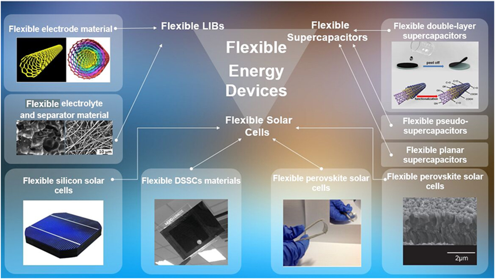
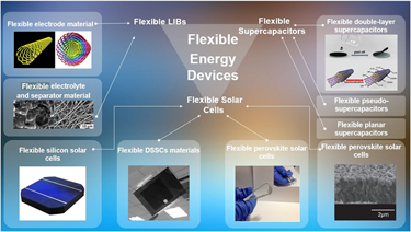
The demand for flexibility in the field of energy devices has become increasingly important.Reference Zhou, Li and Cheng1,Reference Wang, Lu, Liu, Chen, Tong and Shen2 Wearable smart devices have been brought to reality from thoughts these years. In 2014, Apple unveiled their smart watch. This novel product hits the market. However, it still receives many criticisms on its battery: users have to charge their watches once or more times per day to guarantee the normal working.Reference Wilson3 It is clear that the performance of batteries applied in small-size devices still needs to be enhanced. Moreover, the flexible battery is urgent to be realized, which can directly change the appearance of such portable products. Actually, technology of flexible energy applications should be conquered first to manufacture ultrathin and portable facilities. The portable devices like smart bands, smart phones, and laptop computers are all calling for highly efficient flexible energy supplier to open up an innovation process. In recent years, researchers have invested efforts to realize the flexible energy applications and plenty of bendable energy devices are designed, as shown in Fig. 1.
Latest flexible energy devices with high application potential, including the flexible LIBs and supercapacitors.

Lithium-ion batteries (LIBs) are the ideal devices to power portable products due to their outstanding features like lightweight, high working voltage, high energy density, long repeat service life, and no memory effect. Traditional LIBs mainly consist of the electrodes, the separator, the electrolyte, and the shells. The electrodes are usually metal substrates coated with active materials which are crisp and snapping. Liquid electrolyte is organic solvent solutions of a lithium salt like LiClO4, LiPF6, and LiBF4. The liquid environment is not suitable for flexible LIBs because extrusions or crimps may lead to explosion and other safety issues. Researchers focus on flexible substrates and nonfragile materials to form bendable electrodes.Reference Yu, Yu and Lou4–Reference Amin, Meng, Ahmad, Cheng, Zhang, Mao and Wei16 The solid electrolytes like polymer and gel membranes are gradually developed to replace the traditional separator and liquid electrolyte.Reference Zhang, Zhou, Lin and Zhu17–Reference Manthiram, Yu and Wang23 Up to now, plenty of fully flexible LIBs have been prepared in labs; different ideas provide various ways to realize the flexible structure.
Among the various energy storage devices, batteries and supercapacitors are two of the most potential choices for general application. The batteries exhibit high energy density and can meet the demands of electronic devices.Reference Faraji and Ani24 However, the low cycle numbers and charge/discharge rates limit their applications in high power density situations.Reference Li, Tao, Guo, Zhang, Luo, Chen and Pan25,Reference Gao, Wu, Ding, Liu and Lou26 A supercapacitor is a new storage device whose capacity is between conventional capacitors and batteries. They own high power density, high charging efficiency, excellent cycle performance, and environment friendliness.Reference Lekakou, Sorniotti, Lei, Markoulidis, Wilson, Santucci and Khalil27 There are three main types of supercapacitors at present: electric double layer capacitors, pseudo capacitors, and hybrid capacitors. The electric double layer capacitors have two equivalent electrical double layers, while the pseudo capacitors store charges by efficient and reversible chemical reactions occurring on the surface of the electrode. The hybrid capacitors colligated the advantages of both capacitors above, generating high specific capacity and conductivity by composite materials. The supercapacitors come into fast development in flexible design in recent years. Except developments in all-solid-state structure design, ultrathin flexible planar supercapacitor technology has become mature, which has the potential to be volume-produced.Reference Dai, Wang, Lv and You28 Among the three energy applications above, the seeking for flexibility structures have made great progresses in recent years. Researchers have applied various novel composite materials to form soft facilities and varieties of new structures have been designed. Due to the shortages of some flexible designs like the light weight of the electrodes of the printed supercapacitors or low electronic conductivities of polymers, researchers have synthesized plenty of hybrid materials to overcome the challenges.Reference Ramadoss, Yoon, Kwak, Kim, Ryu and Jang29–Reference Zhang, Li, Zhang, Qian, Niu, Hu and Zhu37 The ultimate goal for flexible energy application designs is to produce efficient energy suppliers adapting to diverse purposes and situations with excellent electronic and mechanical properties, which will genuinely benefit our life.
II. FLEXIBLE LIBS
A. Materials for flexible electrodes of LIBs
Regardless of the electrolyte states, the separating membranes are supposed to be bendable enough to fit in different force situations. The flexibility of the battery shell can be realized by adopting flexible conductive materials. Meanwhile, corresponding technologies have been matured, materials like soft aluminum pouches and tough polymers are ideal for packing flexible LIBs.Reference Saw, Ye and Tay38,Reference Muldoon, Bucur, Boaretto, Gregory and Di Noto39 Therefore the key issue turns to the flexibility of the electrode for producing flexible LIBs. The traditional method of manufacturing is to use the metal sheet to be the substrate while active materials are pasted on one side. The types of LIBs are inflexible as the metals may not recover after being bended and the active materials will break or even fall off. Therefore, the ideas of making flexible electrodes are based on seeking alternative flexible materials.Reference Qiu, Jiao, Xia, Zhong and Chen40,Reference Balogun, Yu, Huang, Li, Fang, Liu and Tong41 To overcome the defects of metal substrates and improve the mechanical properties of anode and cathode active materials, researchers have made plenty of attempts.
1. Carbon nanotubes for flexible electrodes of LIBs
Carbon nanotubes (CNTs) have broadened application prospects in LIBs due to the excellent electrical conductivity, thermal conductivity, and mechanical properties.Reference Wang, Jiang and Shen42,Reference Yoon, Lee, Kim, Park, Cho and Jeong43 The one dimensional tubulous structure can build the supporting framework of flexible electrodes. Traditional electrode materials are usually made of material powder, binder, and conductive agent. By adding binder materials poly(vinylidene fluoride) (PVDF), the active materials are bound to the current collector. Because of the shrinkage or cracking of the binder, the electrode materials are easy to fall off from the current collector while flexible electrodes are free from the problem. Using the CNTs to construct the current collector achieves outstanding effects: closer contact with the active materials, lower contacting resistance, and better mechanical properties. Wang et al. prepared a novel type of light and flexible CNT current collector: active materials show excellent adhesive force on the CNT base comparing with metal current collectors.Reference Wang, Luo, Wu, He, Zhao, Wang and Fan44 The electrode owns great flexibility and integrity, resulting in a preferable electrical performance. The charge/discharge platforms are extended and the capacity increases apparently comparing with the metal substrate ones. Recently, there has been growing focuses in investigating CNT films with particular nanostructures owning enhanced properties of integrity and stability to realize the large-scaled energy storage devices. Hu et al. reported a fully foldable LIB with electrodes adopting CNT microfilms as the current collectors.Reference Hu, Wu, Zhong, Zhang, Suresh, Mehta and Koratkar45 A large area CNT microfilm paper that consists of CNT bundles was prepared by methanol mediated floating catalyst chemical vapor deposition at a temperature of 1150 °C. The prepared CNT microfilms are lighter than a printer paper and such large area films can be mass produced. Li4Ti5O12 and LiCoO2 coated with active materials show a slight decrease in capacity but have super flexibility that can be folded up multiple times.
2. Graphite and graphene for flexible electrodes of LIBs
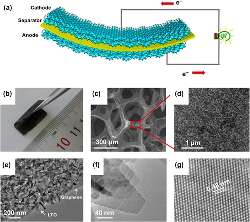
As one of the main selections of anode materials in LIBs, graphite is commonly explored in the research studies of flexible electrodes. Graphite has been investigated for a long age due to its good thermal properties and conductivity and relative products gain wide applications in many areas like precision molds and electrode materials.Reference Gao, Yoshio, Qi and Wang46 Graphene became a hotspot since it was lab prepared in 2004.Reference Novoselov, Geim, Morozov, Jiang, Katsnelson, Grigorieva and Firsov47 Graphene attracts researchers to apply it into energy facilities due to super properties: excellent strength, high conductivity, and ideal quantum effects.Reference Raccichini, Varzi, Passerini and Scrosati48,Reference Bonaccorso, Colombo, Yu, Stoller, Tozzini, Ferrari and Pellegrini49 However, the growth of graphene, modification, and actual applications remain to be studied.Reference Tian, Shu, Cui, Mi, Yang, Xie and Ren50 By inserting Si into the graphene and coating with SiOx, a self-assembly flexible anode of LIB was prepared as reported by Bai et al.Reference Bai, Yu, Kung, Wang and Jiang51 The embedment of Si enhances the mechanical strength of the graphene and tightens the hierarchical architecture of graphene which do good to the capacity. Another potential technique of producing flexible graphene is the method of electrophoretic deposition. The electrophoresis deposition is to set materials in a liquid environment and then attach on the surface of the electrode under the drive of electric force. By setting different voltages, electrode distances and solution concentrations can reach the expected thickness and density of the samples. An outstanding advantage of electrophoresis deposition is that whether the substrate is smooth or not, the materials can entirely deposited on the surface. Such property allows the flexible substrates to shape in different types, providing a tolerance of rough substrates like nickel foams and cellulose. Oakes et al. reported free-standing graphene foam by electrophoresis depositing the CNTs directly from a solvent solution.Reference Oakes, Cohn, Westover and Pint52 The graphene is precisely growing on the nickel foam and the CNTs are electrophoresis deposited to enhance the mechanical strength and conductivity. The 3D structure shows high flexibility and has wide application potential in energy facilities. With their two-dimension structure, graphene nanosheets can build up various macroscopic structures, e.g., thin films and papers, opening new windows for graphene applications.Reference Yun, Wang, Shen, Dou and Zhang53,Reference Liu, Liu, Wu, Huang, Tang, Su and Feng54 A free-standing hybrid paper fabricated by combining graphene nanosheets and CNTs to be the current collector was reported by Hu et al.Reference Hu, Li, Wang, Li and Sun55 The CNTs are dispersed between the graphene sheets and preserve high mechanical strength and flexibility for the forming papers. The material replacing metals to be the current collector can also choose graphene.Reference Chen, Fu, Zhu, Luo, Wang, Li and Danner56 Li et al. adopted graphene foam as current collector and Li4Ti5O12 and LiFePO4 as anode and cathode.Reference Li, Chen, Ren, Li and Cheng57 Prepared graphene pieces are soaked in a suspension of active materials and organics. After maintaining in a temperature of 130 °C for 3–12 h, the electrodes are cooled to room temperature. The prepared electrodes own the properties of lower weight and sufficient flexibility, and the 3D structure of the fabricated battery is shown in Fig. 2(a). From the schematic, it is clear that with flexible graphene foams wrapping around, the LIB shows better performances in good flexibility and buffer ability. The assembled LIBs are fully charged in a very short time due to the characteristic of graphene foam. At the same time, flexible LiFePO4/graphene and Li4Ti5O12/graphene electrodes which can obtain high charge and discharge rates up to 200 C have been invited. The hybrid material-based electrodes show good flexibility [Fig. 2(b)], and in Fig. 2(c), a 3D structure inside the electrode can be seen. Li4Ti5O12 doped inside forms a vertical sheet structure towards the graphene film surface which decreases the diffusion length of the electrode and enlarges the interface areas for a faster transferring of Li ions [Figs. 2(d) and 2(e)]. Figure 2(f) displays the transmission electron microscope (TEM) image of the LTO sheets, and the nanosheet is controlled in only few nanometers in thickness. Furthermore, Fig. 2(g) shows that the nanosheets are highly crystallized at the lattice fringe spacing of 4.8 Å, which is correspond to the regular facet of spinel Li4Ti5O12.
(a) Diagrammatic figure of the flexible battery with a cathode and an anode made from the interconnected graphene foam. (b–d) Characteristics of a flexible LTO/GF electrode: (b) photograph of a flexible LTO/GF being bent (2 × 2 cm2), (c and d) SEM images of the LTO/GF, (e) TEM image of the LTO/GF, (f) TEM image of the LTO nanosheets in LTO/GF, and (g) TEM image of a LTO nanosheet showing lattice fringes with a spacing of 0.48 nm. Reprinted with permission from Ref. Reference Li, Chen, Ren, Li and Cheng57. Copyright (2012), National Academy of Sciences.

3. TiO2 for flexible electrodes of LIBs
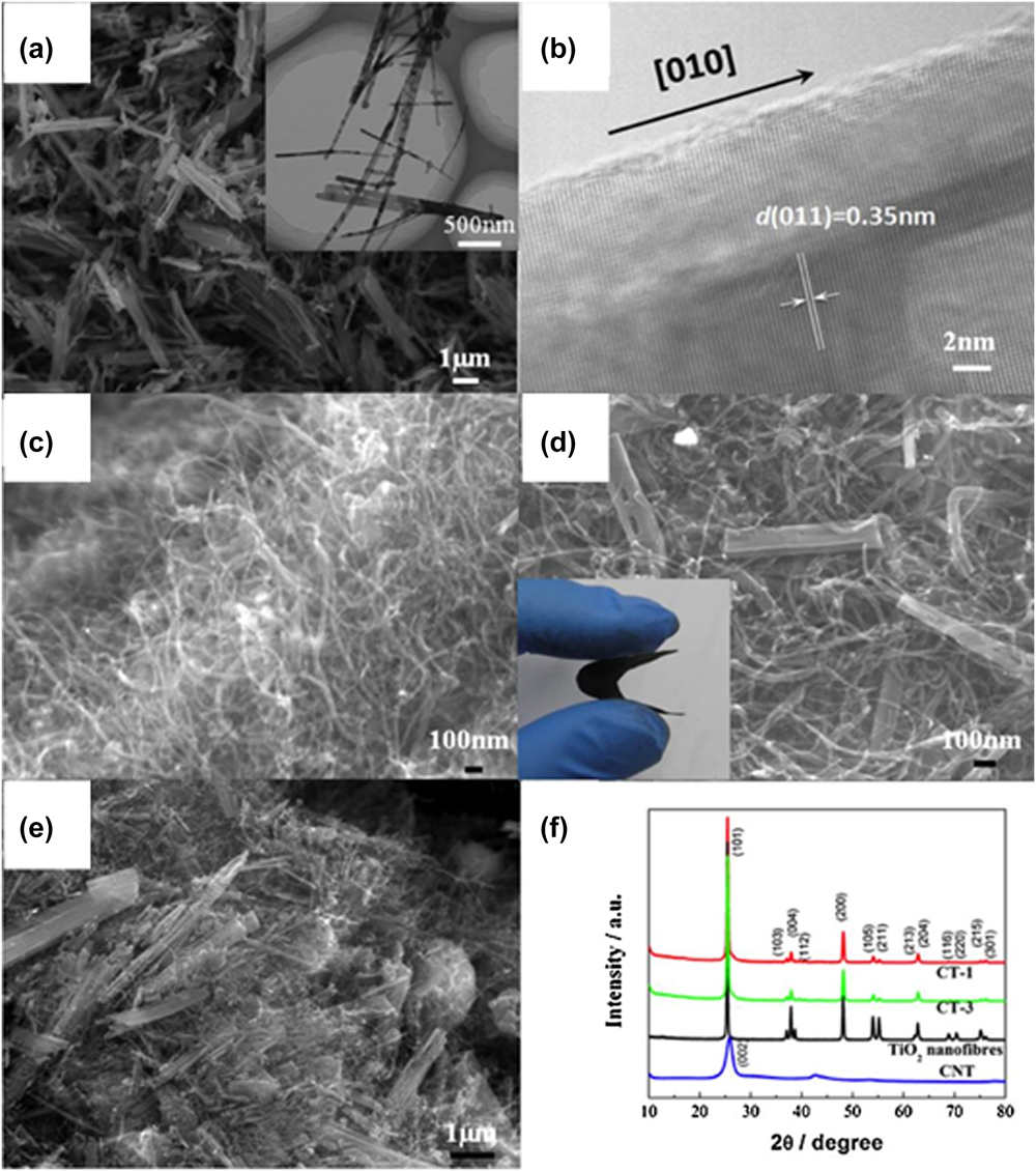
In recent years, TiO2 gains wide concerns as a key material of anode for its significant advantages: environmental friendly, easy to prepare, and stable chemical properties. Besides, its lithium intercalation potential reaches about 1.7 V which avoids generating lithium dendrites and SEI films. Especially with the development of nanotechnologies, anode fabricated by nano-TiO2 has bigger interfacial volume percentage and shorter diffusion distance which facilitates the insertion–extraction of Li+. The disadvantage of TiO2 as an electrode material is the poor conductivity, which limits the electrochemical performance. Hu et al. prepared a flexible graphene–TiO2 paper without binder by a simple progress of filter.Reference Hu, Sun, Sun, Yu, Lu, Liu and Lian58 With the intercalation of TiO2 nanoparticles, the thickness of graphene-based papers increases which benefits the insertion–extraction of Li+. The discharge and charge capacities of the first cycle are 405 and 237 mA h/g, respectively. The discharge capacity increases to 269 mA h/g at the second cycle. The hybrid of the graphene and the TiO2 also improves the conductivity as the electrode shows a lower resistance than the reference TiO2 electrode (43 versus 77 Ω). Zhang et al. prepared a CNT and TiO2 nanofiber composite film without the binders and conventional copper current collector.Reference Zhang, Qiu, Zheng, Liu, Ling, Martens and Zhang59 Figures 3(a) and 3(b) are SEM and HRTEM images of the prepared film while Fig. 3(c) is for CNTs. The TiO2 nanofibers are restricted in a diameter under 100 nm with 5–10 μm in length as shown in Fig. 3(a). TiO2 nanofibers grew a length of 0.35 nm along the [010] direction in Fig. 3(b) and we can see a demonstration of CNTs from Fig. 3(c) which owned size of under 50 nm in diameter and 5 μm in length. Figures 3(d) and 3(e) are photos of CT-1 composites and bended CT-1 films (CT-1: pure CNTs to TiO2 nanofibers of 1:1). The TiO2 fibers were dispersed into the CNT net structures with different ratios for exploring the suitable proportion of TiO2. And Fig. 3(f) is the XRD patterns. The assembled battery with the ratio of 1:1 shows a discharging capacity of 150 mA h/g at the initial cycle and remains 90% after 100 cycles. The contrast pure TiO2 nanofibers appeal a sharp attenuation of capacity in 20 cycles (only 12.5% of capacity remains). From the case shows that with active materials like graphene or CNTs, the low conductivity of TiO2 is overcome and performances of the assembled LIBs are greatly improved. In a nutshell, the composite films doped with TiO2 are great potential flexible electrode materials due to its structure of stability and flexibility, as well as the remarkable electrochemical performances.
Materials characterization of the as-prepared thin films: SEM (a) and HRTEM (b) images of the TiO2 nanofibers, SEM images of the multiwall CNTs (c), the freestanding CT-1 composites: (d) photograph of the bended CT-1 film [the inset of (d)], and CT-3 (e), and XRD patterns (f). Here, CT-1 and CT-3 represent pure CNTs to TiO2 nanofibers of 1:1 and 1:3. Reprinted with permission from Ref. Reference Zhang, Qiu, Zheng, Liu, Ling, Martens and Zhang59. Copyright (2013), Elsevier.

4. Cellulose for flexible electrodes of LIBs
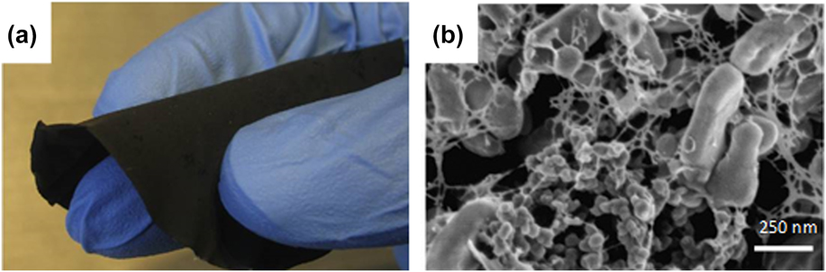
Research on nanopapers and nanofilms based on cellulose has advanced quickly since the cellulose separator was first used as strong papers in 1996.Reference Kuribayashi60 Cellulose is a kind of abundant renewable resources in nature, which can manufacture special papers with features of high dielectric constant, high mechanical performance, and degradable. The cellulose is utilized in producing both electrode binder material and separator material, which means the possibility of more convenient battery manufacture. The integration of product manufacturing is beneficial to the industry: if the battery component preparation can all use the same process (for instance: roll-to-roll or filtration) and basic materials to complete, the cost of manufacturing will be reduced, battery production will be more efficient, and management becomes convenient. When used as the electrode material, the cellulose is expected to replace traditional flexible materials like polymers, which are limited by the defects of low cycling stability, low energy density, and high self-discharge. A paper-making process is mostly used to produce the cellulose-based electrodes: after the pulped fibers are well prepared, cellulose fibers and active material particles are randomly dispersed in water. Usually carboxymethyl cellulose (CMC) is added to be the binder material and limits fibers’ flocculation during filtration, then the slurry is filtered on the filter paper under vacuum. After a drying process, the paper electrode is revealed from the filter paper. Leijonmarck et al. prepared a batch of paper electrodes by filtration of water dispersion of nanofibrillated cellulose (NFC), LiFePO4, and Super-P carbon particles.Reference Leijonmarck, Cornell, Lindbergh and Wågberg61 The appearance of the LiFePO4 paper electrode indicates an excellent flexibility [Fig. 4(a)]. Figure 4(b) is the SEM image of the top of the LiFePO4 paper electrode. The web-like structure of NFC is clear to see with the larger LiFePO4 and smaller Super-P carbon particles binding in from Fig. 4(b). The tensile test shows that using cellulose as the binder results in a mechanically strong but still flexible electrode. While increasing the proportion of cellulose fibers in the composite, as Jabbour et al. reported, the Young’s modulus increases, indicating an improvement of mechanical property but a decrease of conductivity correspondingly.Reference Jabbour, Destro, Chaussy, Gerbaldi, Penazzi, Bodoardo and Beneventi62 They prepared a low-cost, self-standing, and flexible LiFePO4/carbon black/cellulose fiber paper-cathode for LIBs, and the water-based filtration process fully demonstrates the ecofriendly advantage of fibrillated celluloses. A similar water-based filtration process is used for manufacturing flexible cellulose/graphite paper anodes. Jabbour et al. prepared a flexible and thin cellulose fiber/graphite powder anode for LIBs.Reference Jabbour, Destro, Gerbaldi, Chaussy, Penazzi and Beneventi63 Compared with the testing results obtained with a reference graphite powder/PVDF anode, it shows that the cellulose fiber/graphite powder anode obtained better specific discharge/charge capacities, which is associated with porous net structure generated by the beaten cellulose fibers.
(a) Figure of a flexible single-layered LiFePO4 paper electrode. (b) SEM image of the LiFePO4 paper electrode. Reprinted with permission from Ref. Reference Leijonmarck, Cornell, Lindbergh and Wågberg61. Copyright (2013), Elsevier.

5. Other materials for flexible electrodes of LIBs
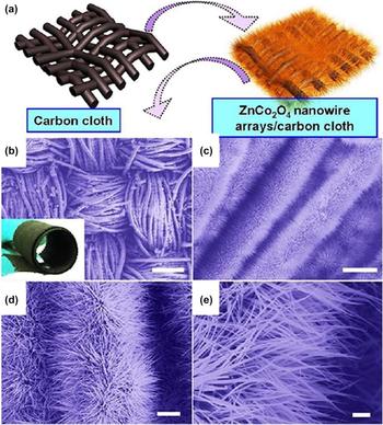
The choices of substrate materials and active materials are diverse. Liu et al. synthesized a hierarchical ZnCo2O4 nanowire arrays/carbon cloth composite layer as binder-free anodes for LIBs. Performances show a high cycle capacity of 1300–1400 mA h/g and after 160 cycles, the capacity still reaches 1200 mA h/g.Reference Liu, Zhang, Wang, Chen, Chen, Zhou and Shen64 The high density ZnCo2O4 nanowire arrays could be smoothly grown on the carbon cloth thus the method is easy to operate as Fig. 5(a) shows. Also from the Fig. 5(b), it shows that the cloth can be twisted as a surface, indicating high flexibility. Figures 5(c) and 5(e) illustrate the uniformity and neatness of the ZnCo2O4 nanowires. Zhu et al. used the reduced graphene oxide/Fe2O3 composite to be the anode material and fabricated electrode by adding polytetrafluoroethylene to measure its performances.Reference Zhu, Zhu, Murali, Stoller and Ruoff65 Fe2O3 is abundant, low cost, and nontoxic, and its theoretical specific capacity is much higher than graphite materials. However, the process is quite complicated, the varied reactions and the reduction process may along with side reactions.
(a) Schematic illustration of the synthesis of flexible 3D ZnCo2O4 nanowire arrays/carbon cloth. Morphology characterization. (b–e) Typical FESEM images of the ZnCo2O4 nanowire arrays growing on carbon cloth at different magnifications. Scale bars: (b) 200 μm; (c) 20 μm; (d) 5 μm; (e) 1 μm. Reprinted with permission from Ref. Reference Liu, Zhang, Wang, Chen, Chen, Zhou and Shen64. Copyright (2012), American Chemical Society.

B. Materials for flexible solid electrolytes and separators of LIBs
Although traditional LIBs with a liquid electrolyte are still predominant products in the market because of their cost superiorities at present, the proportion of sales of polymer LIBs grows rapidly. Solid electrolyte LIBs like polymer LIBs have plenty of outstanding advantages comparing with liquid electrolyte LIBs: high storage capacity, low self-discharge, thinner (thickness less than 1 mm), and shape controllable.Reference Tsao and Kuo66,Reference Juang, Hsieh, Chen and Chen67 Another important point is the safety issue, under special operation situations like high temperature, overcharge, punctured, and under pressure, the liquid electrolyte and electrodes may occur strong interactions, resulting in burning or explosion.Reference Wang, Ping, Zhao, Chu, Sun and Chen68 Thus the traditional separator membrane and the liquid electrolyte are not safe choices for flexible LIBs which are supposed to withstand all directions of deformation. As solid electrolytes are widely researched these years, they are concurrently thought to be a key point of constructing flexible LIBs.
1. PVDF and relative materials for electrolytes of LIBs
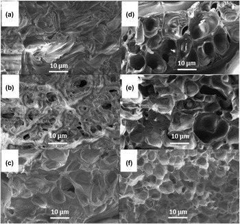
Through the solid electrolyte structures, solid polymer electrolytes are mostly promised to be the flexible material of LIBs. Wright et al. first synthesized complexes of alkali metal ions with poly(ethylene oxide) and proposed the concept of polymer electrolyte in 1975.Reference Wright69 The polymer membranes are used in LIB design since Armand et al. prepared membranes with high ionic conductivity.Reference Berthier, Gorecki, Minier, Armand, Chabagno and Rigaud70 Till now, the polymer membranes have been optimized to obtain high discharge capacity and good circulation property. Conventionally, we mostly use the PE, PP, and PP/PE/PP films as the membrane materials.Reference Yang and Hou71 Membranes made by these materials generally have good electrochemical properties, but relatively the porosity is low and the wettability is poor. These shortcomings restrict the conventional membranes to be set in the liquid electrolyte environment. PVDF is the ideal material of flexible separator due to its good thermal stability and electrochemical stability.Reference Seidel, Jeschke, Vettikuzha and Wiemhöfer72 By means of the phase separation, it is convenient to form the PVDF separator with high porosity. The required amounts of membrane materials were dissolved in a mixture of organic solvent. After stirred for hours at a certain temperature, the solution was equably casted on the glass plate and then dried in vacuum for one day. During this process, the organic solvent evaporated, and the voids left forming micropores, whereas the disadvantage of the phase-separation method is that the forming pores are not size controllable.Reference Venault, Liu, Wu, Yang, Chang, Lai and Aimar73 Similarly, a process of thermally induced phase separation employs a high temperature module to contain the solution and quickly cooled in a low temperature water bath. Extract materials like ethanol and tetraethoxysilane take the work of forming pores through the extracting process.Reference Liang, Wu, Wan, Huang and Xu74 However, PVDF itself is easy to crystallize and the formed membranes are relatively crisp. Efforts have been made to improve the properties of PVDF membranes. Idris et al. prepared a type of microporous PVDF/poly(methylmethacrylate) (PMMA) membrane using the phase-separation method.Reference Idris, Rahman, Wang and Liu75 The SEM images of the porous membrane’s cross section with PVDF/PMMA (wt%/wt%) varying from 100/0 to 0/100 are shown in Fig. 6. From the images, it shows that the pore size of the membrane continues to increase with the addition of PMMA successive to 70 wt% and then starts to decrease. Larger pores mean more smooth channels for ions to transfer thus it is an effective way to improve the ionic conductivity of batteries by the means of phase-separation. The degree of crystallinity of a polymer membrane decreases with PMMA added to the composite, as well as increasing the porosity and electrolyte absorptivity. PVDF-HFP is also used in the preparation of all solid electrolytes because of its enhanced properties of absorbency and mechanical strength. For the purpose of improving the ionic conductivity of the solid electrolytes, Zalewska et al. applied supramolecular compound technology to gel electrolytes, adding an anion receptor to the membranes based on PVDF-HFP.Reference Zalewska, Bernakiewicz, Bystrzycka, Marczewski and Langwald76 Various electrolytes are tested by adding the amount of receptors and the result shows that in LiBF4, the ionic conductivity increases to 6.3 × 10⁴ S/cm when 20 mmol of receptors added in 10 cm3 of salt solution (1 M/L); however, the degree of crystallinity also decreases and the resistance of the layer only changes subtly.
Cross-sectional SEM images of the porous membrane for samples of PVDF/PMMA (wt%/wt%) at (a) 100/0, (b) 70/30, (c) 50/50, (d) 30/70, (e) 10/90, and (f) 0/100. Reprinted with permission from Ref. Reference Idris, Rahman, Wang and Liu75. Copyright (2012), Elsevier.

2. Cellulose for electrolytes of LIBs
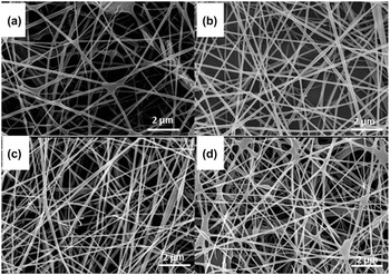
As introduced earlier, cellulose fibers are also widely used as separator materials, owing to the ecofriendly advantage and good performances in electrochemical tests.Reference Ding, Qin, Liu, Zhang, Zhang, Hu and Cui77 Three types of cellulose fibers are basically used to prepare membranes: natural celluloses, microcrystalline celluloses, and CNFs. However with the intense investigations in cellulose fibers, these years, more and more new types of fibers are chosen. Hydroxyethyl cellulose is widely utilized in the areas of adhesive, colloid protective agent, dispersant, and emulsifier with its excellent properties of dispersion, emulsification, gluing, and water protecting.Reference Azzaoui, Mejdoubi, Lamhamdi, Zaoui, Berrabah, Elidrissi and Al-Deyab78 Using the hydroxyethyl cellulose, Li et al. prepared a dense cellulose-based membrane which can absorb organic liquid electrolytes as high as 78.3 wt%.Reference Li, Wang, Yang, Chang, Wu and Holze79 The organic liquid electrolyte is absorbed by the cellulose-based membrane appears an enhanced retaining ability with evaporate temperature increases from 40 °C (commercial separators) to 75 °C. A papermaking method is also popularly adopted because of its easy and fast operation process. As for CNFs, they usually involve two types of concepts: superfine fibers with fiber diameter less than 100 nm or fill nanoparticles to the fibers to modify their properties. The technology of electrospun is commonly used in CNF-based membrane production.Reference Xu, Zhu, Han, Luo and Wang80,Reference Lei, Qu, Lin and Wang81 The process of electrospun includes dissolving the materials to relevant concentration, choosing relative needles according to the surface tensions, and the materials are extruded out under high potential. The solvents are volatilized and forming a crossing structure on the substrates. The electrospinning technique can produce controllable nanoscale fibers stably with high surface area. Qiu et al. synthesized modified CNF nanometer materials using cellulose derivative carboxymethyl cellulose acetate butyrate (CMCAB).Reference Qiu, Shao, Yang, Wang, Wang, Xie and Zhang82 CMCABs are successfully electrospun as shown in Figs. 7(a) and 7(d). We could see that when the mass ratio of solvent dichloromethane: ethanol changing from 9:1 to 6:4, the spinning becomes denser and thicker. The surface of the fibers is smooth and the thicknesses are generally uniform. Testing results of the assembled LIBs show that the capacity reaches 160.8 mA h/g in the first cycle at a rate of 2 C and reduces only 5.11% after 200 cycles.
SEM photos at different mass ratios of dichloromethane to ethanol solvents of electrospun CMCAB nanofibers. The mass ratio of solvent dichloromethane to ethanol was (a) 9:1, (b) 4:1, (c) 7:3, and (d) 6:4, when other spinning conditions remain unchanged. Reprinted with permission from Ref. Reference Qiu, Shao, Yang, Wang, Wang, Xie and Zhang82. Copyright (2013), Elsevier.

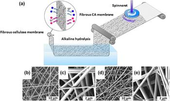
The disadvantage of electrospinning is that the spin area is restricted which limits the commercial application. Instead of driving fibers with high voltage forces in the electrospinning process, the technology of force-spinning (FS) adopts centrifugal forces gained from high rotating speed of spinnerets. Figure 8(a) shows a clear sketch about how FS fabricate fibrous cellulose membranes. It provides a wider scope of operation, and more choices of materials. The method shows high potential in large-scale applications. Weng et al. utilized the technology of FS to produce fibrous cellulose membranes.Reference Weng, Xu, Alcoutlabi, Mao and Lozano83 Figures 8(b) and 8(e) show the SEM images of FS cellulose acetate and fibrous cellulose in different scales. The SEM images show that the threading materials are uniformly distributed on the substrates. The nonwoven cellulose membrane has an uptake ability of electrolyte up to 370% and a porosity as high as 76%. Moreover, it achieves an ionic conductivity as high as 2.12 S/cm. Thus the testing results show that the presented method of FS provides a viable way of fabricating high performance battery components efficiently.
(a) Schematic representation of large-scale fabrication of the fibrous cellulose membrane separator using the forcespinning® technique and subsequent alkaline hydrolysis treatment. (b and c) SEM images of FS cellulose acetate and (d and e) fibrous cellulose membrane. Reprinted with permission from Ref. Reference Weng, Xu, Alcoutlabi, Mao and Lozano83. Copyright (2015), Springer.

A variety of cellulose fiber materials have been synthesized by researchers. As reported by Zhang et al., a renewable, thermal resistant and flame sustain separator was first produced.Reference Zhang, Yue, Kong, Liu, Zhou, Zhang and Duan84 The separator was prepared via a vacuum filtration process with inflaming retarding materials added in it. The separator is a potential separator for improving the safety issue of LIBs owing to its good flame retardency, stable thermal stability, and simultaneous electrochemical characteristics. Xu et al. prepared a novel separator membrane using cellulose microfibers which were modified by mussel-inspired polydopamine with a papermaking process.Reference Xu, Kong, Liu, Zhang, Wang, Liu and Cui85 The membrane shows a huge potential of modification of cellulose fibers to improve its shortage in low ionic conductivity values and chemical stability. Cellulose fibers are also used as filling materials to the membranes to improve the mechanical properties. Cases show that when the cellulosic substrate is added to the membrane materials, the gel polymer ionic conductivity thereupon decreases. It is known that relatively the addition of inorganic fillers in the polymer improves the characteristics of the electrolyte significantly. Chiappone et al. added cellulose handsheets containing alumina nanoparticles to the polymer electrolyte: after pulping the cellulose fibers to prepare the handsheets, a suspension of alumina is added to prepare the handsheets.Reference Chiappone, Nair, Gerbaldi, Zeno and Bongiovanni86 The obtaining membranes have improved mechanical properties and enhanced thermal characteristics, together with a rise of conductivity by comparison with the control groups. More and more attention is being paid on the capacity and safety of LIBs for its wider use and higher performance demands. The requirements of thinner, safer, and more flexible LIBs have been developed rapidly.
III. FLEXIBLE SUPERCAPACITORS
Supercapacitors are of great significance as energy storage devices. Owning to the high rate capability, supercapacitors are promising for next-generation energy source. Compared with batteries, energy storage of supercapacitors is based on the formation of the electrolyte double-layer in the electrolyte/electrode interface. This is a physical process instead of a chemical process, thus the rate capability of supercapacitors is much higher than rechargeable batteries. To realize its flexibility, two main factors are worth to be noted: the choosing of materials and control of electrode structures. Recently, the utilization of solid electrolyte facilitates the assembly of flexible supercapacitors.Reference Li, Song, Wang, Feng, Liu, Zeng and Wang87,Reference Scalia, Bella, Lamberti, Bianco, Gerbaldi, Tresso and Pirri88 In the past years, carbon and advanced carbon materials such as graphene had been explored extensively. The properties of light weight and high compatibility make them promising for flexible supercapacitors. CNTs, due to their high flexibility and strength, also attract extensive attention. On the other hand, structures like planer supercapacitors assembled using ultrathin electrodes exhibit both high flexibility and good electrochemical performances as reported. In this section, investigations in the flexible supercapacitors, materials, and structures for different types of supercapacitors are summarized.
A. Materials for flexible electrical double-layer supercapacitors
1. CNTs for flexible electrical double-layer supercapacitors
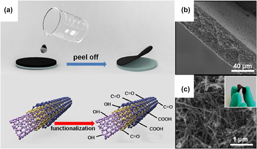
The electronic performances and mechanical strength of the composite materials determine the properties of the fabricated flexible supercapacitors.Reference Cao, Zheng, Shi, Yang, Fan, Luo and Zhang89,Reference Xu, Wang, Yuan, Wei, Gu, Liu and Xu90 Neoteric structures and novel manufacturing methods open up efficient ways for producing flexible supercapacitors. Double-layer supercapacitors can be perceived as two plating electrodes with reverse electric charge, while the distance between two sides is much closer than the regular capacitor which brings high capacity to them. Generally, the double-layer supercapacitor is composed of two electrodes, membrane, electrolyte, and current collector. The flexible electrode substrates can be applied to both current collectors of anode and cathode due to the same active materials. The mixture of polymer and carbon materials such as polymer gels with CNTs, with the advantages of high conductivity and full elasticity, gains high attention in research studies in flexible supercapacitors in recent years. High conductivity carbon-type materials induce enhancement of electrical properties for polymer materials which are lack in capacitance and electronic conductivities. And the flexible skeletons formed by polymers support the bendable structures of electrodes or solid electrolytes with high ion conductivity and stability. The CNT is an important nanomaterial with advantage in mechanical, electrical, and thermal properties. To increase the specific capacitance of CNTs, attempt like adding redox active functional groups on CNTs to increase the specific capacitance performance has been researched. Xiao et al. reported methods to introduce the active redox functional groups to the CNT membranes by annealing at different temperatures.Reference Xiao, Li, Peng, Jin, Zhong, Hu and Chen91 The vacuum filtration method was used to prepare the flexible free-standing CNT films. Figure 9(a) illustrates the fabrication process of the functioned CNT film. After the vacuum filtration method, the CNT film is dried and peeled off from the membrane. With an efficient electrochemical enhancement method, the redox active functional groups are added to the CNTs as shown in Fig. 9(a). Figure 9(b) shows the SEM image of the cross section of the film, and the film is orderly with a thickness of 45 μm. The enlarged image of the functioned CNT film [Fig. 9(c)] shows that the materials are well linked together uniformly. The functional CNT film shows nice flexibility and high electrochemical performance.
(a) Schematic of the fabrication procedure for functionalized freestanding CNT films. (b) Cross-sectional SEM image of the functionalized freestanding CNT film. (c) Enlarged cross-sectional SEM image of the functionalized freestanding CNT films. The inset is the digital image of a functionalized freestanding CNT film. Reprinted with permission from Ref. Reference Xiao, Li, Peng, Jin, Zhong, Hu and Chen91. Copyright (2014), Elsevier.

Transition metal-based layered double hydroxide materials have attracted much attention due to their changeable functions by choosing diverse component elements. High ion exchange ratios and good heat stability also urge researchers to dope such materials in flexible electrode materials to improve the properties. Zhao et al. inserted a hierarchical nanostructure composed of NiMn-layered double hydroxide on the CNT backbone.Reference Zhao, Chen, Xu, Shao, Zhang, Wei and Duan92 The assembling of flexible asymmetric supercapacitors used Nafion/KOH electrolyte and the reduced graphene oxide/CNT counter electrode. Great electrochemical cycle ability is obtained with the addition of NiMn-layered double hydroxide and the all-solid-state supercapacitor is fully bendable.
2. Graphite and graphene for flexible electrical double-layer supercapacitors
Graphite and graphene also possess high potential in future energy devices due to their high conductivity and superb mechanical strength. Mandal et al. added gold nanoparticles to the flexible graphite electrode.Reference Mandal, Pal, Arun and Chanda93 They utilize the filter paper to be the substrate and immerse it in a gold nanoparticle solution. After that, a layer of graphite is exfoliated on the paper surface. The introduction of gold nanoparticles enhances the capacitance of the graphite to 4.3 times higher and increases the electronic conductivity. Xin et al. prepared a novel flexible electrode made of graphite, graphene, and polyaniline.Reference Xin, Wang, Liu, Zhang, Wang, Huang and Zang94 Graphite is set as the electrode in a process of electrochemical exfoliation to form a layer of bendable graphene. Polyanilines, with advantages of low cost and high capacitance, are deposited on such a flexible substrate. The self-assembling graphene also enhances the electronic conductivity, which acts as the main shortage of polyanilines. A high area capacitance of 1.36 F/cm2 and a power density of 275 W/kg are shown in the electrochemical measurements. Similarly, Xiao et al. adopted graphene and polyaniline to form a flexible electrode for supercapacitor.Reference Xiao, Yang, Zhang, Liu, Xiao, Wan and Liu95 They dispersed the reduced graphene onto a normal paper and after drying for a while, the paper is treated by a HI solution. The graphene is reduced through the treatment and the generated CO2 bubbles let the graphene layer naturally fall off. After that, a layer of polyaniline and another graphene layer are added to form a fully bendable electrode with enhanced performances. The flexibility for graphite and graphene supercapacitor electrodes depends on novel producing methods and is also based on the retaining of considerable capacitance and power density.
B. Materials for flexible pseudo-supercapacitors
The energy density of the double-layer supercapacitor has been the critical challenge for further applications. Researchers developed the pseudo-supercapacitor which possesses highly reversible chemical sorption/stripping or redox reactions in both surface and inside of the electrodes. Different from LIBs, there is no intercalation and de-intercalation in pseudo-supercapacitor which offers better power density than LIBs. Bendable solid electrolyte with high safety and good electrical performance is also urgently called for flexible pseudo-supercapacitors. Meanwhile, a gel polymer electrolyte made by 1-ethyl-3-methylimidazolium tetrafluoroborate ([EMIM][BF4]) enhanced PVDF-HFP was designed. The addition of ([BMIM][BF4]) generates more surface charge which attracts more polymer electrolytes which benefits the transfer of ions. High energy density up to 92 W h/kg is gained. Furthermore, the graphene supercapacitor shows excellent cycle stability remaining capacity more than 90% after 12,000 cycles. Chee et al. fabricated a flexible supercapacitor depositing a composition of polypyrrole/graphene oxide/zinc oxide (PPy/GO/ZnO) on the flexible nickel foam to be the working electrode.Reference Chee, Lim, Harrison, Chong, Zainal, Ng and Huang96 The PPy/GO/ZnO electrode layer utilized in the pseudo-capacitor enhances the energy density up to 10.65 W h/kg. Xu et al. designed a novel supercapacitor adopting flexible porous gold wires to be the electrode substrate.Reference Xu, Hu, Sun, Yang, Liu and Huang97 The electrode material selects MnO2 and the gold wires apparently increase the electrical conductivity of MnO2. As an asymmetric supercapacitor, the counter electrode chooses the CNT/carbon paper. By advantages of the MnO2, the supercapacitor gains high capacitance as 12 mF/cm2 and remains 90% after 2000 cycles. Moreover, with the improvement of porous gold wires, the supercapacitor forms a fully flexible structure and high power density of 2.531 μW/cm2.
C. Materials for planar supercapacitors
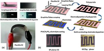
As the flexible printed circuit technology matures, various components are set in the flexible plastic substrate but the power supply has been the matter.Reference Han, Zhang, Tang, Li and Wang98 The appearance of planar supercapacitors makes it possible for planar devices’ power supplying. With the advantages of flexibility and ultrathin, the planar supercapacitors have attracted much attention for their high application potential in microdevices.Reference Ramadoss, Yoon, Kwak, Kim, Ryu and Jang29,Reference Bettini, Piseri, De Giorgio, Arbizzani, Milani and Soavi99,Reference Hu, Pei and Ye100 The appearance of this new kind of supercapacitors also makes wearable devices more possible since their miniature size is more suitable for insertion.Reference Liang, Wang, Huang, Cheng, Zhao, Hu and Qu101 In a planar supercapacitor, the electrode materials are distributed in the same plane to form an interdigitated structure which reduces the membranes and the layer-by-layer fabrication in conventional supercapacitors. Separators are also saved since the electrodes are able to be closely placed, which allows ions to transport smoothly and results in high power density. As such, the key point for planar supercapacitors is to find an electrode with good stability of circulation, high specific capacitance, and high flexibility.Reference Yu, Tetard, Zhai and Thomas102 Furthermore, a preparation scheme applying more efficient technology for materials deposition is also important.Reference Sundramoorthy, Wang and Gunasekaran103,Reference Kang, Chung, Kim and Kim104 Zeng et al. prepared a microsupercapacitor based on porous gold/MnO nanowire electrodes.Reference Zeng, Long, Zhou, Guo, Wang and Hu105 MnO and MnO2 have high theoretic capacity and abundant reserves but they are often cooperated with high conductive materials to enhance their conductivities. Porous metals show high potential to be the hybrid material and is first used in planar supercapacitor in this research. The results show a relative high power density of 3.4 W/cm3, above those of other MnO-based supercapacitors. The capacitance is over 1000 F/g and has good cycle ability which remains 85% after 1000 cycles. Raj et al. covered the graphite electrode with a thin film of polymer polypyrrole to improve the surface conductivity.Reference Raj, Kim, Cho, Lee, Jung, Kim and Yu106 A high area capacitance of 23 mF/cm2 is obtained when utilizing the electrode into an all solid flexible supercapacitor. To make the microsupercapacitor, the prepared graphite/polymer polypyrrole/Au planar electrodes are immersed in the poly(vinyl alcohol)/H3PO4 solution to form the solid electrolyte which leads the supercapacitor to be bendable. The fabricating details of the electrodes and supercapacitors are shown in Fig. 10. In Fig. 10(a), the flexibility of the supercapacitor is fully revealed. Graphite nanoflakes are spread on the substrate and the polymer polypyrrole is coated on the graphite nanoflakes by electrodeposition. The materials together with the substrate show great flexibility. Figure 10(b) shows the fabrication progress of the planar supercapacitor, and after the scraping of graphite and the electrodeposition of polymer polypyrrole, the gold conducting electrode is deposited and the PVA/H3PO4 solid state electrolyte is casted on the electrode. A comparison with the traditional graphite electrode shows that the flexible electrode has an enhanced conductivity and capacitance. Using the aluminum coated paper as a substrate, the activated carbon as the electrodes for two sides, and the chloride-based solvents as the electrolyte, Pettersson et al. prepared an environmentally friendly supercapacitor.Reference Pettersson, Keskinen, Remonen, Von Hertzen, Jansson, Tappura and Österbacka107 The roll-to-roll printing and manufacturing method are used in the research, which offers an inexpensive and propagable commercial potential of such supercapacitors.
(a) Photographic demonstration of electrodes and SC fabrication steps. (b) Fabrication steps of planar SC and the photograph of SCs with and without gold electrode. Reprinted with permission from Ref. Reference Raj, Kim, Cho, Lee, Jung, Kim and Yu106. Copyright (2015), American Chemical Society.

Ink-jet printing technology has been used for many years, as a part of the graphic printing, and it can directly print materials to the substrates with different patterns.Reference Wang, Yin, Hao and You108 Wang et al. used the CNT/Ag to be the ink and by adding MnO2, the solution is printed on the substrate to form a 2 μm thick flexible thin electrode.Reference Wang, Liu, Tao, Yang, Liu, Shi and Gao109 The inkjet printing is developed with mature application as a convenient, efficient, and low cost deposition method. It also has potential in applying in the latest electronic device printing. Instead of the conventional methods, Sun et al. used a 3D micro-extrusion system to print the graphene-based electrodes.Reference Sun, An, Chua, Pang, Zhang and Chen110 They design a printing head which includes a piston, a syringe, and a changeable microneedle, then set it on the precision motor to print the materials. The device suits the applications in on-chip systems and flexible electronics. Furthermore, Liu et al. utilized the electrophoretic deposition method to disperse the reduced graphene oxide/polypyrrole on interdigitated electrodes.Reference Liu, Qian, Xu, Zhou, Guo and Yan111 The prepared all-solid-state device reaches a high capacitance of 147.9 F/cm3. The power density reaches 1300 mW/cm3 and remains 71.7% after 5000 cycles. The case indicates that the strong potential of utilizing electrophoretic deposition in flexible device’s production as the method has advantages of high efficiency, uniform coating, and potential of mass production.
IV. CONCLUSION AND PROSPECTIVES
The current development of two kinds of energy applications’ flexibility has been summarized and analyzed in this review. The research studies of flexible component materials like CNTs, graphene, and NFCs have made much progress. More technologies are innovatively applied to fabricate flexible devices: printing technologies, co-evaporation processes, and electrophoretic deposition methods. However, the present flexible applications are still facing two challenges: the first one is the poor electrical properties and performance comparing to the rigid devices, and the second one is the large-scale application of equipment. The property challenges are hopefully being solved if the flexible devices can be released from the small-size structures in labs. It can be expected that flexible energy applications will eventually change the energy structure profoundly and transform our life enormously.
ACKNOWLEDGMENTS
The work is supported by UESTC new faculty startup fund, the National Natural Science Foundation (Grant No. 21403031), and the Fundamental Research Funds for the Chinese Central Universities (Grant No. ZYGX2014J088).