I. INTRODUCTION
Automobile lightening has attracted lots of attentions in automobile industry in past decades. To reduce the weight of automobiles as much as possible, light materials with high strength and ductility are widely investigated and some of them are successfully used in different parts of automobiles. Reference Li, Lin, Jiang and Chen1,Reference Topaç, Ercan and Kuralay2 High-strength low-alloy (HSLA) steel with the fine ferrite matrix and pearlite microstructures is the representative one, thus it is a very important material for wheel rims. Reference Carboni, Beretta and Finzi3–Reference Yakubtsov, Poruks and Boyd5
As a typical resistance welding, flash-butt welding is applied in the forming of wheel rims because of the advantages of high welding efficiency and speed. As well known, wheel rims were made from a rectangular sheet metal by bending and welding. For the bending process, the yield ratio of the material decides the plastic formation ability, and for the HSLA steels the yield ratio meets the requirements of bending process. Reference Kuroda, Ikeuchi and Ikeda6,Reference Zhang, Lai, Zhu and Wang7 Cemil Cetinkaya Reference Çetinkaya and Arabaci8 pointed that the mechanical properties and microstructures of 16MnCr5 chain steel were influenced by welding parameters. Reference Bhattacharyya, Adhikary, Das and Sarkar9–Reference Zerbst, Klinger and Clegg11 For the welding process, coarse Widmannstatten ferrites in the weld and a certain degree of soften phenomenon in the heat affected zone (HAZ) affected the mechanical properties of welded joints and ultimately affected the quality of the wheel rims. Reference Xia, Sreenivasan, Lawson, Zhou and Tian12–Reference Odanovic, Ristivojevic and Milosevic-Mitic15 Therefore the flash-butt welding played an important role in the forming process of the wheel rims, and the change of welding parameters affected the microstructures and mechanical properties of flash-butt welded joints, which ultimately affected the forming quality of the wheel rims. Reference Yu, Feng, Qin, Zhang and He16,Reference Zheng, Yuan, Sun and Pan17 To ensure good quality of wheel rims, the microstructural and mechanical properties of flash-butt welded joints under different welding parameters should be investigated.
The present investigations were aimed at evaluating the influence of welding parameters on microstructure and mechanical properties of HSLA 590CL welded joints in wheel rims by separately adjusting single parameters such as flash allowance, upset allowance, and upset pressure. Moreover, the cracking statistics in the practical production of wheel rims was collected and the fracture mechanisms of wheel rims were investigated.
II. EXPERIMENTAL DETAILS
A. Material and forming process
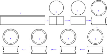
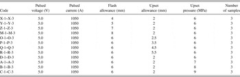
The chemical composition of B590CL steel is shown in Table I. The dimensions of B590CL plate selected in the forming process of the wheel rim are 1720 × 284 × 4.5 mm. The main forming processes for the rim as shown in Fig. 1 are as follows: blanking → edge rolling → butt welding → welding slag cleaning → flaring → first rolling → second rolling → third rolling → expansion and finishing → punching valve hole. Flash, as we know, is typically caused by leakage of materials between the two surfaces of a workpiece. Flash allowance is the length of reservation, considering that the surface of workpiece will be burnt out in the flash stage, a reasonable length can guarantee the joints quality and save in materials. Correspondingly, upset allowance is the length of reservation, considering that the flashed surface will be shorten in the upset stage, upset allowance will affect the effect of plastic deformation. Upset pressure are the forces between the two surfaces to ensure the extrusion of liquid metal in the weld, an appropriate upset pressure can avoid the pores and cracks. Therefore, the three flash-butt welding parameters are important to the quality of welded joints. The welding parameters selected in this study are given in Table II. The pulsed voltage and current were constant, the effect on microstructures and mechanical properties of flash-butt welded joints was investigated by adjusting the flash allowance, upset allowance, and upset pressure, respectively. The flash allowances were chosen as 4, 5, 7, and 8 mm, the upset allowances were chosen as 2.5, 3.5, 4.5, and 5.5 mm, the upset pressures were selected as 6, 7, 8, and 9 MPa. Three samples were prepared and investigated under each group of welding parameter.
Chemical composition (wt%) of B590CL HSLA steel.

Main forming processes for the wheel rim: 1: blanking; 2: edge rolling; 3: butt welding; 4: flaring; 5: first rolling; 6: second rolling; 7: third rolling; and 8: expansion and finishing.

Welding parameters selected in the study.

B. Microstructure observation and mechanical tests
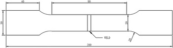
The welded joints were cut down from the wheel rims under each group of welding parameters, then these samples were grinded and polished, and etched with 4% Nital solution. An LEICA DMI5000 optical microscope was used to observe the microstructures of the flash butt welded joints. Moreover, the micro-hardness measurement was performed on typical welded joints by using Vicker’s hardness tester. The shape of the wheel rims was cylindrical after the flash-butt welding. Therefore, according to the GB/T228-2002 Chinese standard, the tensile samples were cut down from the wheel rims straightened by a large press machine, and the shape and size of the tensile test samples are given in Fig. 2. The tensile tests were carried out by a universal hydraulic testing machine.
The shape and size of the tensile test samples (mm).

C. Cracking analysis
In the process of real production for the wheel company, the selected welding parameters such as flash allowance, upset allowance, and upset pressure were 2 mm, 2.5 mm, and 6 MPa, respectively. According to the data statistics of the practical production, it was found that the wheel rims fractured at the expanding procedure frequently. Thus the fracture mechanism of the wheel rims in the expanding process was evaluated. The fracture samples were cut from the failed wheel rims in the expanding procedure. Then these specimens were observed by using a scanning electron microscope (SEM) equipped with energy dispersive spectroscopy (EDS).
III. RESULTS AND DISCUSSION
A. Microstructural results
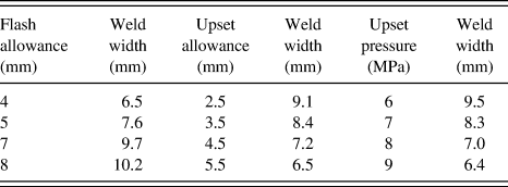
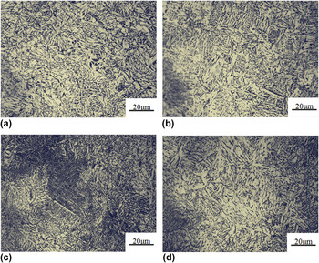
With the adjustment of the flash-butt welding parameters, the weld widths of the wheel rims were different. The measured weld widths under different welding parameters are shown in Table III. Along with the increase of flash allowance, the weld width changed from 6.5 to 10.2 mm. The weld microstructures for four different flash allowances are shown in Fig. 3. The optical images indicated the Widmanstatten ferrites and a few bainite for weld metals. From Fig. 3 we found that Widmanstatten ferrites and grain size tended to increase. While the flash allowance was 10 mm, the enter weld area was full of Widmanstatten ferrites. When the flash-butt welded metal cooled to a temperature below Ae3, the austenite transformed to allotriomorphic ferrite that grew from the prior austenite grain boundary. The austenite to Widmanstatten ferrite transformation was a displacive transformation with the growth rate controlled by the combination of carbon diffusion. Reference Ali and Bhadeshia18–Reference Okaguchi, Ohtani and Ohmori20 The high heat input in the welding was beneficial to the diffusion of carbon, thus the Widmanstatten ferrites were formed from the coarsened austenite grain. Flash allowance, as the length of reservation, was to guarantee the enough flashing of two surfaces of wheel rims. Low flash allowance discouraged the diffusion of carbon in the weld, ultimately led to the serious Widmanstatten ferrites and influenced the welding quality. To obtain well weld microstructures, flash allowance values should be optimized in the flash butt welding process.
Weld width under different welding parameters.

Weld microstructure for four different flash allowance: (a) 4 mm, (b) 5 mm, (c) 7 mm, (d) 8 mm.

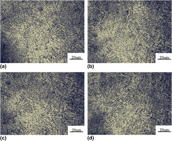
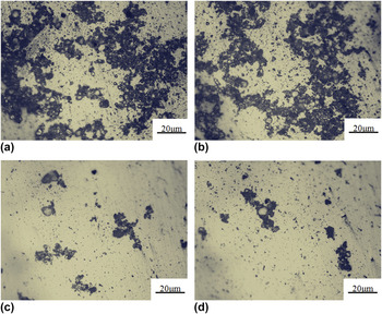
With the increasing of upset allowance, the gaps between welding surfaces became bigger, and the range of plastic deformation expanded, so the weld width decreased from 9.1 to 6.5 mm. The weld microstructures for four different upset allowance are shown in Fig. 4. Considerable Widmanstatten ferrites were found in the weld metal, as the upset allowance changed from 2.5 to 5.5 mm, the amount of bainite tended to rise. Increasing upset allowance was beneficial to improve plastic deformation property of welded zone, thus improving the performance of welded joints. The nonmetallic inclusions in weld metal under four different upset allowances are shown in Fig. 5. As the upset allowances were 2.5 and 3.5 mm, some amount of the nonmetallic inclusions occurred in weld metal. When the upset allowance increased to 4.5 and 5.5 mm, the amount of inclusions reduced drastically. The source of nonmetallic inclusions was in the process of the flash-butt welding. The liquid metal and inclusions existed in the weld after the flashing stage, the upset allowance and upset pressure would affect the effect of plastic deformation and extrusion of liquid metal and inclusions considering that the flashed surface shortened in the upset stage. So the appropriate upset allowance was conducive to squeeze out the nonmetallic inclusions in weld metal.
Weld microstructure for four different upset allowance: (a) 2.5 mm, (b) 3.5 mm, (c) 4.5 mm, (d) 5.5 mm.

Nonmetallic inclusions for four different upset allowance: (a) 2.5 mm, (b) 3.5 mm, (c) 4.5 mm, (d) 5.5 mm.

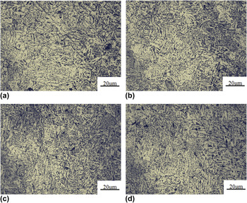
With the increase of upset pressure, enough plastic deformation occurred in the end face of the steel plate, the recrystallization in the weld metal was drastic, and the weld width decreased from 9.5 to 6.4 mm. The weld microstructures for four different upset pressure are shown in Fig. 6. It can be found that with the increase of upset pressure, the amount of Widmanstatten ferrites increased and the grain size progressively got smaller. It was because that enough plastic deformation occurred in the two surfaces of wheel rims under the larger upset pressure. In addition, the liquid metal and inclusions in the weld were extruded out. Not only the welded joints cleanness can be improved, but also the high strength of welded joints in wheel rims can be obtained.
Weld microstructure for four different upset pressure: (a) 6 MPa, (b) 7 MPa, (c) 8 MPa, (d) 9 MPa.

B. Tensile results and micro-hardness
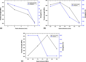
The tensile results of welded joints under different welding parameters are given in Fig. 7. It was found that the tensile strength and elongation of welded joints decreased with the flash allowance increased, and the strength was decreased at 623.3 MPa as the flash allowance was 8 mm. It was caused by the oversized flash allowance, which led to the grain coarsening. The tensile strength changed from 661.7 to 666.7 MPa with the increasing of upset allowance from 2.5 to 3.5 mm, then the strength reduced to 655 MPa while the upset allowance was 4.5 mm, the tensile strength was lowest at 626.7 MPa as the upset allowance was 5.5 mm. It was caused by the over plastic deformation of welded joints. Therefore, the forming quality of welded joints was poor and tensile strength was lower. When the upset pressure increased from 6 to 8 MPa, the tensile strength increased from 641.7 to 676.7 MPa, and as the upset pressure was 9 MPa, the tensile strength decreased to 653.3 MPa. It is the result of grain deformation that is caused by larger upset pressure due to which the tensile strength decreased for the grain deformation.
Tensile results under different welding parameters: (a) flash allowance (b) upset allowance (c) upset pressure.

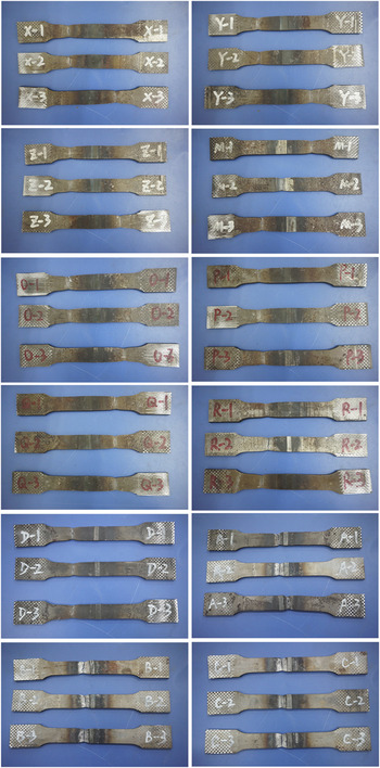
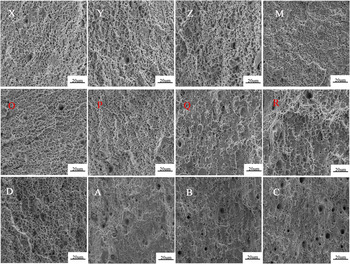
The fracture locations of tensile samples under different welding parameters are given in Fig. 8. The fracture surfaces of tensile samples under different welding parameters are shown in Fig. 9. All tensile samples were fractured at base metal location, the fracture surfaces were characterized by a typical ductile fracture, the equiaxed dimples were main feature, and a few spherical inclusions were found in the bottom of the dimples. But as the flash allowance was 8 mm, the size of dimples was small and the fracture surface presented cleavage steps. The fracture mode under the four different upset allowances showed the ductile fracture. Fracture surface was characterized by uniformly distributed equiaxed dimples as the upset allowance were 2.5 and 3.5 mm. Except for the equiaxed dimples, there were parabolic shearing dimples observed in the fracture surface and its size was large. The existence of shearing dimples indicated that over plastic deformation was likely to be occurred in the process of welding joints forming. The welded joints were fractured at base metal when the upset pressure was 6 MPa and when the failure location was HAZ under the other upset pressures. Equiaxed, shearing dimples and micro-voids were found in the fracture surface.
Fracture locations of tensile samples under different welding parameters.

Fracture surfaces of tensile samples under different welding parameters: Flash allowance: (X) 4 mm, (Y) 5 mm, (Z) 7 mm, and (M) 8 mm. Upset allowance: (O) 2.5 mm, (P) 3.5 mm, (Q) 4.5 mm, and (R) 5.5 mm. Upset pressure: (D) 6 MPa, (A) 7 MPa, (B) 8 MPa, and (C) 9 MPa.

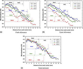
The micro-hardness values of welded joints under different welding parameters are shown in Fig. 10. As the change of flash allowance, the micro-hardness values dropped off gradually from the weld to base metal. While the flash allowance was 4 mm, the average micro-hardness in the weld region was the highest with a value of 308 HV. As the flash allowance increased from 5 to 7 mm, the average micro-hardness in the weld area were reduced from 303.1 to 297.4 HV, respectively. The average micro-hardness in the weld zone was the lowest at 283.5 HV and a certain degree of softening phenomenon was observed at the junction between the weld and HAZ. The micro-hardness values of welded joints changed between 240 and 310 HV with the change of upset allowance. The micro-hardness was the highest when the upset allowance was 3.5 mm and the micro-hardness was the lowest when the upset allowance was 5.5 mm. The lowest micro-hardness value was possibly related to the joint dislocation caused by the larger upset pressure. Along with the increase of upset pressure, the distribution of the micro-hardness values in welded joints was similar. The highest micro-hardness values all appeared at the weld, the average micro-hardness value in the weld zone changed from 301 to 308 HV as the upset pressure increased from 6 to 9 MPa. A certain degree of softening phenomenon in the HAZ was observed. The austentite grains in the HAZ grow because of heat, and become the coarse grains after cooling, which affected the mechanical property and bearing capacity of welded joints due to which tensile samples were fractured at the HAZ.
Micro-hardness values of welded joints under different welding parameters (a) flash allowance (b) upset allowance (c) upset pressure.

C. Cracking analysis of wheel rims
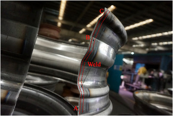
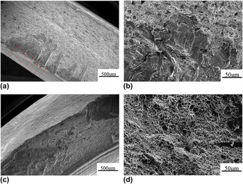
According to the statistics of cracking in wheel rims, there were two types of cracking in the expanding process. Figure 11 showed the first type of cracking in wheel rims, the weld remained intact without cracking and the wheel rim fractured along the HAZ. Obvious plastic deformation and thinning phenomenon were found in the fracture surface, the average thicknesses of location AB and BC were 2.0 and 4.3 mm, respectively. The SEM micrographs of the fracture surfaces are shown in Fig. 12. Thinning location AB [Fig. 12(a)] indicated that crack initiation located at the edge of the fracture surface and the magnified image of the crack source [Fig. 12(b)] displayed a ripple pattern, unfeatured flat faces, and equiaxed dimples. It indicated that the cracking occurred at the thinning location AB firstly, then propagated along the location BC under the expanding pressure. The fracture surface of location B [Fig. 12(c) and 12(d)] showed the characteristics of equiaxed and a handful of shearing dimples, which was the typical ductile fracture. The presence of shearing dimples indicated that tearing happened in the propagation of the cracking from location B to C.
The first type of cracking in wheel rims.

SEM micrographs of the fracture surfaces for the first type: (a) thinning location AB, (b) the magnified image of (a), (c) Location B, (d) the magnified image of (c).

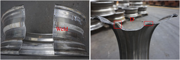
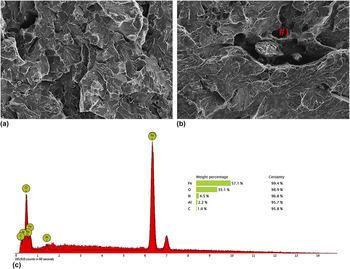
The second type of cracking in wheel rims is given in Fig. 13, the wheel rims fractured at the weld. The fracture surface without obvious plastic deformation was relatively flat and bright, the average thickness was 4.3 mm. Herringbone pattern was observed in the fracture surface by the further observation, the crack initiation and direction of crack propagation can be obtained from the herringbone pattern. In addition, the fracture color of location D was different from the other location of the fracture, which was dark gray. Figure 14 is the SEM micrographs of the fracture surfaces for the second type. It [Fig. 14(a)] showed the typical characteristics of brittle fracture such as cleavage step, fan-shaped, and river pattern. Apart from cleavage characteristic, lumpy inclusions and a few dimples were found in the gray location D [Fig. 14(b)]. The results of energy spectrum analysis [Fig. 14(c)] showed that lumpy inclusions were mainly composed of iron and aluminum oxides. In the expanding process, the presence of these inclusions in the fracture surfaces was related to the upset pressure in the flash-butt welding, which was bad for the fracture toughness of the wheel rims. Due to the stress concentration after flash butt welding, micro-cracks formed between the inclusions and the matrix, then propagated along the inclusions until the failure under the huge expanding force.
The second type of cracking in wheel rims.

SEM micrographs of the fracture surfaces for the second type: (a) typical brittle fracture pattern (b) Location D, (c) EDS analysis result.

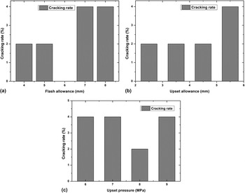
According to the practical production statistics of wheel rims, the cracking frequency of wheel rims under different welding parameters is shown in Fig. 15, there were fifty wheel rims for each parameters. As seen in Fig. 15, the cracking frequency was lowest as the flash allowance were 4 and 5 mm, as the upset allowance were 2.5–4.5 mm, the cracking frequency was small up to 2%, while the cracking frequency was lowest as the upset pressure was 8 MPa. The statistical data of cracking frequency was in accord with the results of mechanical property test. It indicated that changing a single welding parameter was an effective measure to reduce cracking frequency in wheel rims. However, the optimal parameter combinations would be investigated in the further research.
Cracking rate of wheel rims under different welding parameters (a) flash allowance (b) upset allowance (c) upset pressure.

IV. CONCLUSIONS
To study the effect of flash butt welding parameters on the microstructure, mechanical properties of welded joints and fracture analysis of wheel rims, 4.5 mm thick HSLA 590CL sheets were selected as the forming of wheel rims. The results are given as follows:
-
(1) As the flash allowance, upset allowance, and upset pressure were 4 mm, 3.5 mm, and 8 MPa, respectively, the microstructure and mechanical properties of HSLA 590CL welded joints were optimum. The Widmanstatten ferrites and the amount of bainite were found in the weld. The tensile strength of welded joints met the standard of rims steels.
-
(2) Micro-hardness distribution of welded joints in different welding parameters were similar. Micro-hardness values dropped off gradually from the weld to base metal. A certain degree of softening phenomenon was found in the HAZ.
-
(3) The first type of cracking fractured at the HAZ and showed ductile fracture characteristics. The crack initiation is located at the thinning edge of the wheel rims.
-
(4) The second type of cracking is fractured at the weld and showed brittle fracture characteristics. Nonmetallic inclusions were found in the fracture surface, and micro-cracks were formed between the inclusions and the matrix owing to the stress concentration.
ACKNOWLEDGMENTS
The authors would like to acknowledge financial support from the National Natural Science Foundation of China (51305144), Fujian Provincial Natural Science Foundation (2015J01203), Science and Technology Planning Project of Xiamen City under grant (3502Z20113020), Promotion Program for Young and Middle-aged Teacher in Science and Technology Research of Huaqiao University (ZQN-PY203), Science and Technology Key Planning Project of Fujian Province (2008H0085).