Introduction
A proficient antenna array design has a remarkable role in the wireless communication system. A number of research works on the antenna array design are going on over the last few decades for the improvement of far-field radiation characteristics. The growing number of traffic in radio frequency (RF) spectrum has compelled the antenna design engineers to realize the antenna array having low side lobe level (SLL) as well as narrow 3-dB beam width. The narrow beam width is necessary to achieve the high directivity, whereas, a low SLL is the utmost design criteria to minimize the interference with the other radiating systems driving in the same frequency band [Reference Balanis1, Reference Elliott2]. However, the antenna array design with low SLL as well as narrow 3-dB beam width is a challenging one because the improvement of one design aspect will deteriorate the other [Reference Balanis1, Reference Elliott2] and hence, both the design criteria will never be met at the same time.
The presence of mutual coupling between the array elements degrades the performance of the antenna array design [Reference Lui, Hui and Leong3, Reference Gupta and Ksienski4]. But a very few attempts have been made in the past to reduce the effect of mutual coupling [Reference Chakravorty and Mandal5, Reference Das, Mandal, Ghoshal and Kar6] among the array elements. In this paper, the authors have applied an efficient method [Reference Chakravorty and Mandal5] for the CAA design to reduce the mutual coupling among the elements of the array. The reciprocal of driving impedance is called driving admittance which is also known as mutual coupling among the array elements [Reference Elliott2]. The performance of the transmission and reception of the RF signal for the synthesis of CAA is heavily affected due to the mutual coupling [Reference Lui, Hui and Leong3]. This paper presents method [Reference Chakravorty and Mandal5] for minimizing the mutual coupling among the elements of the array by proper controlling the feed currents excitation which in turn reduces the driving admittance of each identical element of the array. The summation of driving admittance of all the elements of the array is reduced efficiently to minimize the mutual coupling among the elements of the array by optimizing the current amplitude excitation weights using different optimization techniques. The approach presented here is a generic one and can be applied for the radiation pattern synthesis of circular antenna array with any number of array elements.
The main objective of this paper is to design a circular antenna array with a low SLL as well as a narrow 3-dB beam width in the presence of mutual coupling. These two prime design criteria of CAA are obtained by the optimal current amplitude excitation weights and the inter-element distance among the elements of the array while the phase difference between any two elements is kept at zero. The method of null control in the far-field radiation pattern using evolutionary optimization technique is discussed in [Reference Mandal, Ghoshal and Bhattacharjee7]. The numerical results show the comparison among genetic algorithm (GA) [Reference Haupt and Werner8–Reference Panduro, Mendez, Dominguez and Romero10], particle swarm optimization (PSO) [Reference Kennedy and Eberhart11–Reference Sahib, Najjar, Dib and Khodier13], simulated annealing (SA) [Reference Ingber14, Reference Rattan, Patterh and Sohi15], biogeography-based optimization (BBO) [Reference Singh and Kamal16], firefly algorithm (FFA) [Reference Sharaqa and Dib17], moth flame optimization (MFO) [Reference Morabito, Donato and Isernia18], and ALO [Reference Mirjalili19–Reference Tung and Chakravorty22] algorithm-based approaches for the design of CAA. Panduro et al. in [Reference Panduro, Mendez, Dominguez and Romero10], employed GA for SLL reduction of 8, 10, and 12 elements non-uniform CAA design. PSO is applied in [Reference Sahib, Najjar, Dib and Khodier13] for the design of non-uniform CAA of 8, 10, and 12 elements. Rattan et al. in [Reference Rattan, Patterh and Sohi15], have applied SA for the optimization of 8, 10, and 12 elements CAA of isotropic radiators. BBO is applied in [Reference Singh and Kamal16] for the synthesis of 8, 10, and 12 elements CAA. Sharaqa et al. in [Reference Sharaqa and Dib17], applied FFA for the synthesis of the same CAA. Morabito et al. in [Reference Morabito, Donato and Isernia18], proposed a simple method based on the aperture antenna theory to give a more complete and assorted overview of the recent developments for the orbital angular momentum (OAM) antennas. In [Reference Das, Mandal, Ghoshal and Kar23], Das et al. have employed MFO optimization technique for the synthesis of the linear antenna array (LAA) and CAA. However, the method discussed in [Reference Das, Mandal, Ghoshal and Kar23] is not practically suitable because the mutual coupling effect is not considered there for design purpose. But, the effect of mutual coupling is an indispensable part for all practical antenna array design issue. In this paper, the authors propose the controlling method of the current ratio for mutual coupling compensation using evolutionary optimization techniques for the design of CAA structure of 8, 10, and 12 elements and the results obtained by employing ALO algorithm are compared with the state-of-the-art algorithm.
The rest part of the paper is arranged as follows: Section II presents the design equation of CAA. Section III shows a brief discussion of the applied algorithm for the design of CAA. Comparative simulation results are presented in Section IV. Finally, Section V concludes the paper.
Design equation
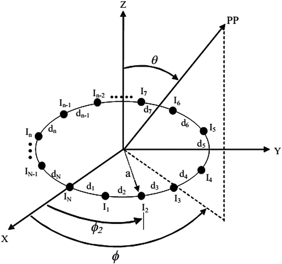
Figure 1 shows an N elements CAA in the x–y plane having a radius “a” and scanning a point PP in the far-field. The radiation pattern of the CAA is represented by its array factor (AF), as all the elements of the array are isotropic, and it is given in (1) [Reference Balanis1].

where


k = 2π/λ, λ is the wavelength of operation, θ and φ represent the elevation and azimuth angle, respectively.φn represents the angular position of the nth element in the x–y plane.
The geometry of N-elements CAA in the x–y plane.

The array factor (AF) is assumed to be in the x–y plane, as presented in this paper. Thus the following changes are made.

Thus, the AF can be rewritten as

where I n is the current excitation amplitude weight of the n th element of the array, d n is the inter-element spacing between the elements “n” and “n + 1”.φ0 is the direction of the main beam, which is chosen to be zero.
The design goal of this paper is to determine the optimal current excitation amplitude weights and inter-element distance for the synthesis of far-field radiation pattern having low SLL as well as narrow 3-dB beam width considering the mutual coupling effect.
In an antenna array, the presence of other antenna elements alters the current distribution, the electromagnetic field distribution and in turn, the input impedance of all the elements of the array. So, the performance of an individual antenna in an array depends not only on its feed currents but also on the currents of its neighbor elements. The input impedance of an antenna in the presence of other array elements is called the driving impedance, which depends on the current ratio, the self-impedance, and the mutual impedance. It is also observed by using induced EMF method [Reference Balanis1] that these three parameters are not related to each other; hence, change in the value of any one of the parameters will change the driving impedance value, keeping the other two parameter values unaltered.
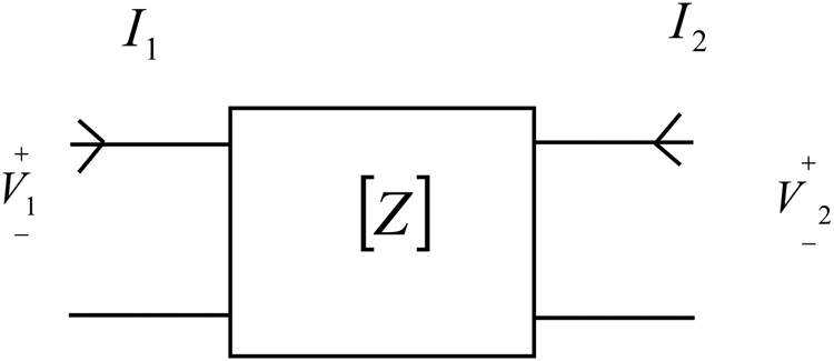
Now, to illustrate the method, consider an antenna array which consists of two elements. So, the antenna array system can be represented by a two-port network, as shown in Fig. 2.


Two-port network.

where Z 11 and Z 22 are the self-impedances of antenna 1 and antenna 2, respectively. Z 12 and Z 21 are the mutual impedances due to the current at port 2 and port 1, respectively.
The presence of other elements will modify the input impedance values and are represented by (8) and (9).


where Z 1d and Z 2d represent the driving impedance of antenna 1 and antenna 2, respectively, which depend on three independent parameters, namely, the current ratio (I 1/I 2), the self-impedance, and the mutual impedance value.
The analysis of driving impedance using the induced EMF method [Reference Balanis1] shows that even though the driving impedance of each array element depends upon the above three parameters, these parameters do not depend on each other.
The induced EMF method [Reference Balanis1] is employed to derive the driving impedance of a non-uniform CAA of N elements. The analysis and understanding of the mutual coupling between the elements of an array can be considerably simplified by considering a non-uniform CAA of N elements which can be represented by an n-port network. The voltage–current relationship in an n-port network is given in (10).


So, the driving impedance can be represented as

The sum of all the driving impedance values for each element of the array is represented as Z Dmn.

where Z md is the driving impedance of the individual array elements. Z mn is the mutual impedance and I n/I m is the current ratio. The analytical expression for the driving impedance calculation using the EMF method for a two-element linear dipole using closed-form solution [Reference Balanis1] shows that the self and mutual impedance values are not related to the current ratio. Hence, in the proposed method, authors have minimized the reciprocal of driving impedance which is also called the driving admittance for the reduction of mutual coupling among the array elements by optimizing the current ratio keeping the Z mnvalue unaltered.
Now to achieve the design objective, a suitable Cost Function (CF) needs to be formulated to reduce the SLL and 3-dB beam width in the presence of the mutual coupling effect as given in (15).

where ZD is the driving impedance of CAA due to the current ratio and is given in (16).

Here, W 1, W 2, and W 3 are the weighting factors and θ max represents the maximum value of θ; θ ms1 and θ ms2 represent the maximum side lobe angles below and above θ max; I n,i is the current excitation amplitude weight of (n, i)th element. 3-dB beam width is the angular width between the 3-dB points on both sides of the main beam. Thus, 3 dBBWComputed and 3 dBBW (In,i = 1) refer to the computed 3 dB beam width for the non-uniform excitation and the uniform excitation case, respectively. The third term in equation (15) is computed only if 3 dBBWComputed >3 dBBW (In,i = 1).
The first term on the right-hand side (RHS) of (15) is used for suppressing the SLL by minimizing the ratio of the summation of AF values positioned on the maximum side lobe at the angle of the upper and lower band of the radiation pattern, respectively, to the maximum AF value; the second term of (15) is used to reduce the driving admittance by optimizing the current ratio for minimizing the mutual coupling, and the third term is used to reduce the 3-dB beam width by minimizing the difference, achieved by non-uniform excitation and uniform excitation, respectively. In this paper, the far-field radiation patterns of 8, 10, and 12 elements CAA are optimized for minimizing the SLL, 3-dB beam width and mutual coupling between the elements of the array. ALO algorithm controls the current amplitude excitation weights and inter-element distances between the array elements to minimize the CF.
Ant lion optimization (ALO) algorithm
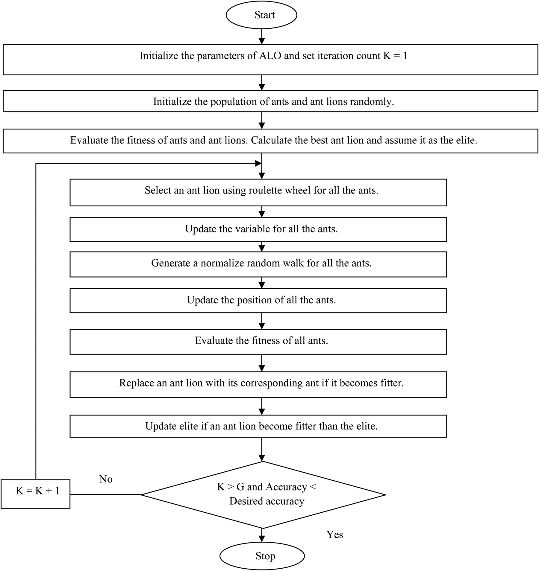
The main inspiration of the ALO algorithm is deduced from the foraging behavior of the ant lions larvae. An ant lion larva digs different sized cone-shaped pits in the sand by throwing out sands by its massive jaw. The larvae hide below the pits and waite for insects to be trapped in the pit. The edge of the cone is made very sharp for insects to slide down to the bottom of the pit easily. When the ant lion senses that a prey is in the trap, it tries to catch it. The ant lions intelligently throw sands to the edge of the pit for the prey to slide down to the bottom of the pit, when the trapped insects try to escape from the pit. After catching the prey, the prey is pulled under the soil and consumed. The behaviors of ant lions and their prey are modelled mathematically in ALO and are discussed in details in [Reference Mirjalili19–Reference Tung and Chakravorty22]. The main steps of the ALO algorithm for the CAA optimization problem are given as a flowchart in Fig. 3.
Flowchart for ALO algorithm.

Results and discussions
ALO algorithm is extensively executed to achieve the normalized optimized current amplitude excitation weights and inter-element distance of the 8, 10, 12 elements CAA. The ALO algorithm is run for 50 times with their best control parameters [Reference Eiben and Smit24] by using MATLAB 7.5 version on Intel Core (TM) 2 processor with 3.00 GHz with 3 GB RAM to obtain the best results.
Numerical results
The results achieved by employing ALO algorithm considering the mutual coupling for CAA design is compared with the uniform pattern and with the state-of-the-art algorithms containing equal sets of the elements which do not consider the mutual coupling for CAA design.
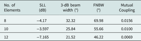
Table 1 shows the results of the uniformly excited (I n,i = 1) and uniformly spaced (d = λ/2) CAA of 8, 10, 12 elements and it is termed as the uniform pattern in the graphical plots in the presented work. The SLL values for the uniform pattern of 8, 10, 12 elements CAA are −4.17 dB, −3.597 dB, and −7.165 dB, respectively, whereas, the 3-dB beam widths of the arrays mentioned above are 32.32°, 25.84°, and 21.52°. The First Null Beam Width (FNBW) values of 8, 10, 12 elements CAA are 69.98°, 55.66°, and 46.22°, respectively, and the mutual coupling values are 0.0156, 0.0100, and 0.0069. The results of Table 1 show that 3-dB beam width and mutual coupling values of the uniform pattern for 8, 10, 12 elements CAA are reduced with the increase in the array elements for the uniform pattern synthesis of CAA.
The initial value of SLL, 3-dB beam width, and FNBW for uniformly excited (I n,i = 1) and uniformly spaced (d = λ/2) CAA.

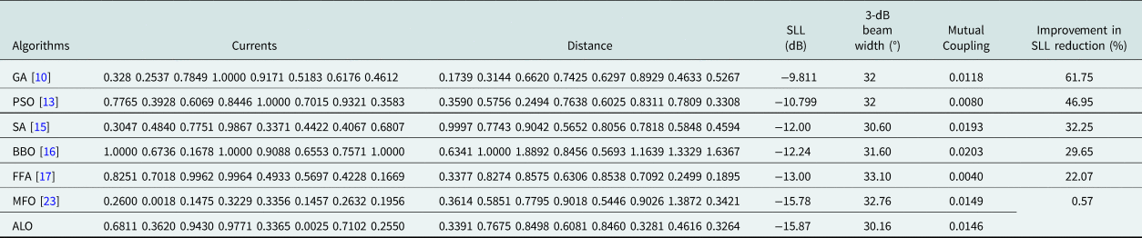
The comparative results of GA [Reference Panduro, Mendez, Dominguez and Romero10], PSO [Reference Sahib, Najjar, Dib and Khodier13], SA [Reference Rattan, Patterh and Sohi15], BBO [Reference Singh and Kamal16], FFA [Reference Sharaqa and Dib17], MFO [Reference Das, Mandal, Ghoshal and Kar23], and ALO algorithms for non-uniformly excited and non-uniformly spaced 8 elements CAA design are shown in Table 2. The table contains the normalized values of current amplitude excitation weights, inter-element spacing, SLL, 3-dB beam width, and mutual coupling values obtained by using different algorithms for 8 elements CAA design. The SLL value of uniform pattern for 8 elements CAA design is −4.17 dB and the value improves to −9.811 dB, −10.799 dB, −12.00 dB, −12.24 dB, −13.00 dB, and −15.78 dB by using GA, PSO, SA, BBO, FFA, and MFO algorithm, respectively. Now by employing ALO algorithm far better results of SLL of −15.87 dB is achieved. The reduction of SLL value is improved to 61.75%, 46.95%, 32.25%, 29.65%, 22.07%, and 0.57% with respect to GA, PSO, SA, BBO, FFA, MFO algorithm as given in Table 2. The 3-dB beam width obtained by using GA, PSO, SA, BBO, FFA, MFO, and ALO algorithms is 32°, 32°, 30.60°, 31.60°, 33.10°, 32.76°, and 30.16°, respectively, whereas, the mutual coupling values are 0.0118, 0.0080, 0.0193, 0.0203, 0.0040, 0.0149, 0.0146, respectively.
Results achieved by employing ALO compared to the other optimization techniques for N = 8 elements CAA.

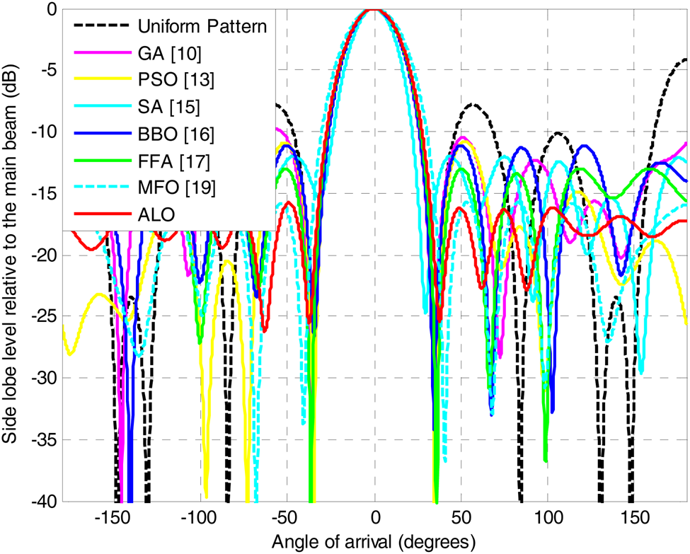
The results obtained by using different algorithms for the non-uniformly excited and non-uniformly spaced 8 elements CAA design are graphically plotted in Fig. 4. The figure shows the far-field radiation patterns obtained by using different algorithms and the comparison with the uniform pattern obtained by using uniform excitation to all the array elements having a half wavelength inter-element spacing. Figure 4 reveals that the ALO algorithm yields the lowest SLL value and lowest 3-dB beam width as compared to other well-established algorithms. The figure shows the superiority of the ALO algorithm over other algorithms visibly.
Array patterns obtained by employing different optimization techniques for the 8-elements CAA design.

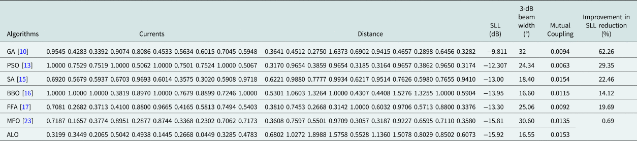
Table 3 shows the results obtained by using ALO algorithm and the results are compared with GA [Reference Panduro, Mendez, Dominguez and Romero10], PSO [Reference Sahib, Najjar, Dib and Khodier13], SA [Reference Rattan, Patterh and Sohi15], BBO [Reference Singh and Kamal16], FFA [Reference Sharaqa and Dib17], and MFO [Reference Das, Mandal, Ghoshal and Kar23] algorithm. The table contains the normalized values of current amplitude excitation weights, inter-element spacing, SLL, 3-dB beam width, and the mutual coupling values achieved by using different algorithms for 10 elements CAA design. Table 3 shows that the authors have obtained muchimproved results of SLL and 3-dB beam width by employing ALO algorithm compared to other well-established algorithms. The SLL value for the uniform pattern for 10 elements CAA design is −3.597 dB which is improved to −9.811 dB, −12.307 dB, −13.00 dB, −13.95 dB, −13.30 dB, and −15.81 dB by using GA, PSO, SA, BBO, FFA, and MFO algorithm, respectively. Now by employing ALO algorithm far better results of SLL of −15.91 dB is achieved. The reduction of SLL value is improved to 62.26%, 29.35%, 22.46%, 14.12%, 19.69%, and 0.69% with respect to GA, PSO, SA, BBO, FFA, MFO algorithm as given in Table 3. Similarly, the 3-dB beam width obtained by using GA, PSO, SA, BBO, FFA, and MFO algorithms is 32°, 24.34°, 18.40°, 16.60°, 25.06°, and 30.60°, respectively. However, the authors have obtained a muchimproved value of 16.55°, 3-dB beam width by employing ALO algorithm. The mutual coupling values obtained by using GA, PSO, SA, BBO, FFA, MFO, and ALO algorithms are 0.0094, 0.0063, 0.0154, 0.0115, 0.0092, 0.135, and 0.0153, respectively.
Results achieved by employing ALO compared to the other optimization techniques for N = 10 elements CAA.

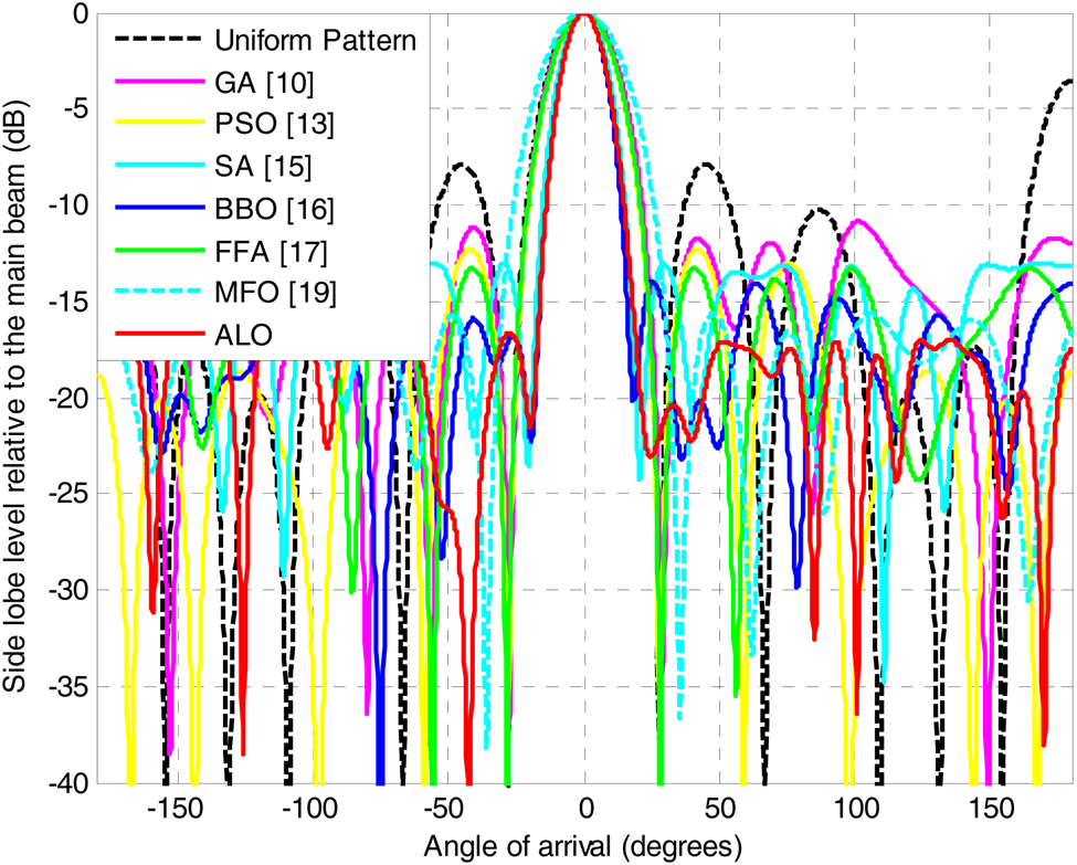
Figure 5 shows the graphical representation of the radiation patterns obtained by using different algorithms for 12 elements of CAA design. The figure also shows the comparison with the uniform pattern obtained by using uniform current excitation to all elements of the array having a half wavelength inter-element spacing. The graphical plots of Fig. 5 show clearly that ALO algorithm-based results yield the lowest SLL and 3-dB beam width values as compared to those of the values achieved by using other well-established algorithms.
Array patterns obtained by employing different optimization techniques for the 10-elements CAA design.

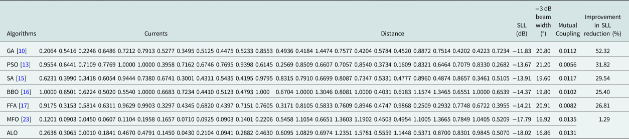
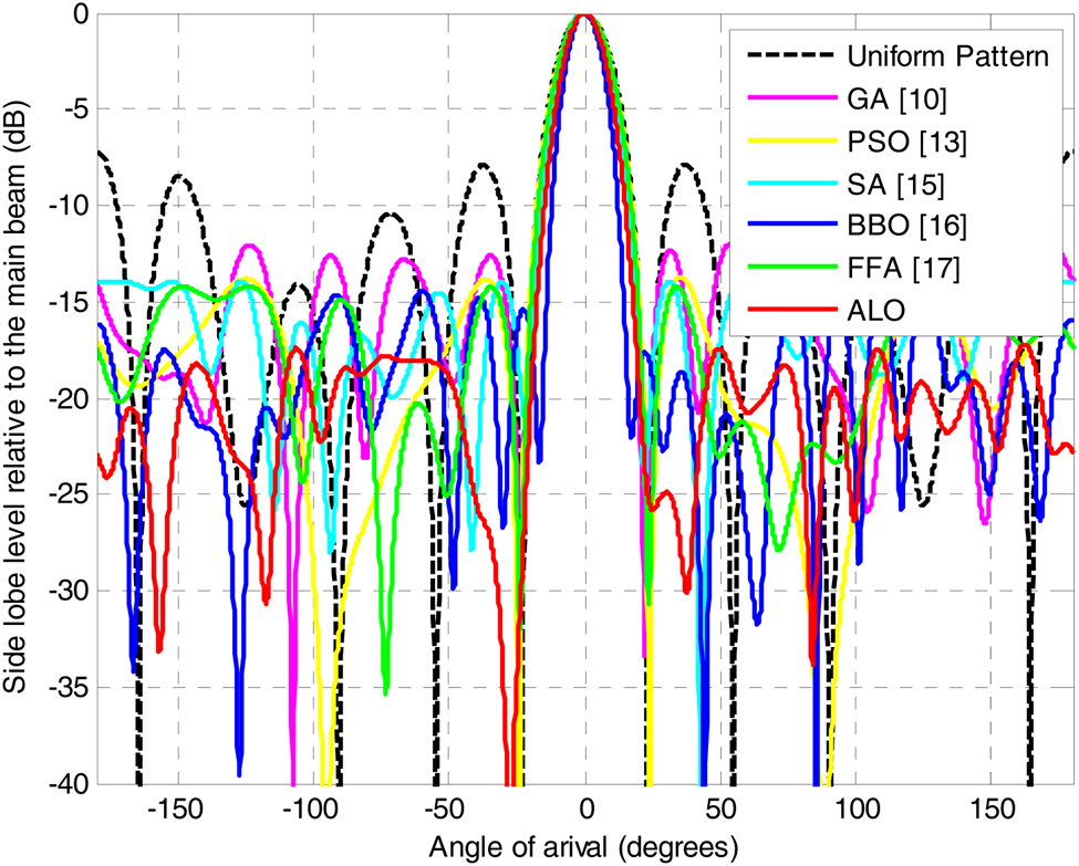
Table 4 depicts the comparative results of the non-uniformly excited and non-uniformly spaced 12 elements CAA design using different algorithms. The authors have applied the ALO algorithm for 12 elements CAA design and obtained far better results of SLL and 3-dB beam width compared to the other well-established algorithms. The SLL values obtained by using GA [Reference Panduro, Mendez, Dominguez and Romero10], PSO [Reference Sahib, Najjar, Dib and Khodier13], SA [Reference Rattan, Patterh and Sohi15], BBO [Reference Singh and Kamal16], FFA [Reference Sharaqa and Dib17], and MFO [Reference Das, Mandal, Ghoshal and Kar23] algorithms are −11.83 dB, −13.67 dB, −13.91 dB, −14.37 dB, −14.21 dB, and −17.79 dB, respectively; whereas, the authors have achieved much better results of SLL of −18.02 dB by employing ALO algorithm. The reduction of SLL value is improved to 52.32%, 31.82%, 29.54%, 25.40%, 26.81%, and 1.29% with respect to GA, PSO, SA, BBO, FFA, MFO algorithm as given in Table 4. The 3-dB beam width values obtained by using GA, PSO, SA, BBO, FFA, and MFO algorithms are 20.80°, 21.20°, 19.60°, 19.80°, 20.91°, and 16.92°, respectively; whereas, by employing ALO algorithm far better 3-dB beam width results of 16.86° is achieved. The mutual coupling value achieved by using GA, PSO, SA, BBO, FFA, MFO ALO algorithms is 0.0112, 0.0056, 0.0117, 0.0102, 0.0082, 0.0135, and 0.0131, respectively.
Results achieved by employing ALO compared to the other optimization techniques for N = 12 elements CAA.

The results of Table 4 are graphically plotted in Fig. 6 which confirms that ALO algorithm yields the lowest SLL and 3-dB beam width values as compared to the other well-established algorithms.
Array patterns obtained by employing different optimization techniques for the 12-elements CAA design.

The overall inference regarding the numerical results shows that the ALO algorithm-based approach for the design of 8, 10, 12 elements CAA for minimizing the SLL and 3-dB beam width considering the mutual coupling performs exceptionally well. All the simulation results and their graphical plots of far-field radiation patterns reveal the superior optimizing capability of ALO over the other well-established algorithms.
Convergence profile plots of the ALO algorithm
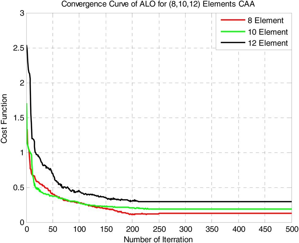
The minimum cost function values against the number of iteration cycles are recorded to get the convergence profile. Figure 7 shows the convergence plots of the ALO algorithm for the design of 8, 10, 12 elements CAA considering the mutual coupling effect.
Convergence plots of 8, 10, and 12 elements CAA considering the mutual coupling effect obtained by employing ALO.

The above plots of convergence expose the outstanding performance of the ALO algorithm in terms of stability and convergence speed.
Accuracy test of ALO
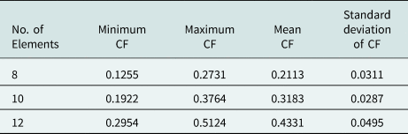
The statistical parameters of CF values obtained by employing the ALO algorithm after 50 independent execution for the synthesis of 8, 10, and 12 elements CAA are given in Table 5.
Statistical performance of CF values achieved by employing ALO.

Table 5 shows that the variation of CF values for the ALO algorithm-based design is small enough for the synthesis of 8, 10, and 12 elements CAA design which proves the robustness and stability of the proposed approach.
Box and Whisker plots
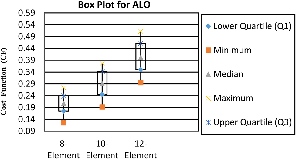
The ALO algorithm has been executed for 50 trial runs to achieve the best results and the resulting CF values attained in each run have been used for box and whisker plots [Reference De, Kar, Mandal and Ghoshal25]. Figure 8 shows the box and whisker plots obtained by employing ALO for the 8, 10, and 12 elements CAA design considering the mutual coupling.
Box and Whisker plots for ALO-based 8, 10, and 12 elements CAA design considering the mutual coupling.

Upper and lower ends of the boxes represent the 75th and 25th percentiles, respectively. Median is represented by tringle. The whiskers are the lines extending from each end of the boxes to show the extent of the rest of the data. Outliners are the data with values beyond the end of the whisker. For 8-elements CAA design, the median value of CF is 0.2072, and the range of variation of CF value is from 0.1255 to 0.2731. Similarly, for 10-elements and 12-elements CAA design, the median values of the CF are 0.2907 and 0.4011, respectively. The range of variations of CF for 10 elements and 12 elements CAA design is from 0.1922 to 0.3764 and 0.2954 to 0.5124, respectively.
The range of variations of CF values is small for 8, 10, and 12 elements CAA design by employing the ALO algorithm. Thus from the whisker plots, it is evident that the ALO-based design offers robust and stable results.
Conclusion
This paper presents an efficient method of optimal far-field radiation pattern synthesis of a non-uniform single ring circular antenna array considering the mutual coupling effect by employing the evolutionary optimization technique known as ant lion optimization. The mutual coupling is considered in the cost function first time in this paper for the synthesis of non-uniform single ring CAA. The results achieved by employing different algorithms for the synthesis of non-uniform single ring CAA for suppressing the SLL as well as reducing the 3-dB beam width are compared in this paper. The performance analysis of different algorithms for the synthesis of non-uniform single ring CAA shows that the ALO algorithm has an excellent prospect to be used as a proficient optimizer to determine the optimal current amplitude excitation weights and the inter-element distances among the elements of the array for the design and pattern modeling of a non-uniform single ring circular antenna array.
Acknowledgements
The authors express their sincere gratitude to SERB, DST, Govt. of India for funding the project under the grant EEQ/2017/000519 dated 23 March 2018. The authors are also thankful to Visvesvaraya fellowship offered by Meity, Govt. of India.
 Avishek Das completed his B.E. degree in Electronics and Communication Engineering and M.Tech. in E.C.E (Microwave) from The University of Burdwan, West Bengal, India in 2008 and 2010, respectively. He received an MBA degree in Human Resource from Sikkim Manipal University in the year 2014 and completed his Ph.D. degree in 2020 from National Institute of Technology, Durgapur, West Bengal, India under Visvesvaraya Ph.D. Scheme for Electronics and IT, Ministry of Electronics and IT, Government of India. Presently, he is working as Assistant Professor in the Department of Electronics and Communication Engineering, Haldia Institute of Technology, Haldia, West Bengal, India and associated as a post Ph.D. researcher at National Institute of Technology, Durgapur, on the project funded by Science and Engineering Research Board, Department of Science and Technology, Government of India (Grant No. EEQ/2017/000519 dated 23/03/2018). His research interests include the application of evolutionary optimization techniques for the design of Antenna Arrays.
 Durbadal Mandal passed B. E. degree in Electronics and Communication Engineering, from Regional Engineering College, Durgapur, West Bengal, India in the year 1996. He received the M. Tech. and Ph. D. degrees from National Institute of Technology, Durgapur, West Bengal, India in the year 2008 and 2011 respectively. Presently, he is working in National Institute of Technology, Durgapur, West Bengal, India, as Associate Professor in the Department of Electronics and Communication Engineering. His research interest includes Array Antenna design; filter Optimization via Evolutionary Computing Techniques. He has published more than 350 research papers in International Journals and Conferences.
 Rajib Kar passed B. E. degree in Electronics and Communication Engineering, from Regional Engineering College, Durgapur, West Bengal, India in the year 2001. He received the M. Tech. and Ph. D. degrees from National Institute of Technology, Durgapur, West Bengal, India in the year 2008 and 2011, respectively. Presently, he is working in National Institute of Technology, Durgapur, West Bengal, India, as Associate Professor in the Department of Electronics and Communication Engineering. His research interest includes VLSI circuit optimization, Signal Processing using Evolutionary Computing Techniques. He has published more than 350 research papers in International Journals and Conferences.