Introduction
In the recent wireless communication era, a dielectric resonator (DR) is a more popular choice in the antenna field. Dielectric resonator antenna (DRA) has some benefits like high gain, large bandwidth, marginal cost, small size, higher radiation efficiency, various feeding method and low metallic losses to compare with planner antennas [Reference Petosa1]. S. A. Long and his research team had demonstrated DRA and studied the field inside the DRA [Reference Long, McAllister and Shen2]. Since then, many researchers have worked and developed different types of DRA for various applications. DRA can be any shape such as cylindrical, rectangular, conical, hemispherical or any other shape but cylindrical and rectangular DRA are more popular due to design flexibility and easily available in the market [Reference Luk and Leung3].
In the last few years, researchers focus on enhancing the impedance bandwidth along with circular polarization (CP) characteristics of DRA. Various techniques are used for enhancement of bandwidth such as using simple slot feed DRA [Reference Ittipiboon, Petosa, Roscoe and Cuhaci4], stacked DRA of different permittivity using partial ground and excited with annular shape microstrip feed line [Reference Sharma and Gangwar5], multilayered half split cylindrical dielectric resonator antenna (CDRA) using coaxial feed [Reference Chaudhary, Srivastava and Biswas6] provides impedance bandwidth of 63.7% (2850 MHz), CP stacked DRA using two pair of rectangular shape dielectric layer [Reference Fakhte, Oraizi and Karimian7] excited via microstrip feed line provides AR bandwidth of 6% (600 MHz) and impedance bandwidth of 21% (600 MHz), stair-shape DRA using a pair of rectangular DR showing impedance bandwidth of 37% (2100 MHz) and 22% (1300 MHz) AR bandwidth [Reference Fakhte, Oraizi, Karimian and Fakhte8], ring DRA using annular shape microstrip line feed with 66.72% (3710 MHz) impedance bandwidth at center frequency 5.35 GHz [Reference Chaudhary, Kumar and Srivastava9], hemispherical DRA having rectangular shape parasitic slot in the ground layer [Reference So and Leung10] and quarter CDRA [Reference Bezerra, Sousa, Junqueira, Silva, Barroso and Sombra11] provides −10 dB bandwidth of 16.56% (390 MHz) and AR bandwidth of 3.6% (80 MHz). However, rectangular DRA of large size using tapered strip [Reference Khalily, Rahim and Kishk12], cylindrical DRA excited by T-shape microstrip line [Reference Bijumon, Menon, Suma, Sebastian and Mohanan13] increases the −10 dB bandwidth from 12 to 26% and rectangular DRA using meandered-line and partial ground plane [Reference Kumar and Chaudhary14] showing impedance bandwidth of 20.67% along with 27.95% AR bandwidth are designed for the enhancement of bandwidth. Some other designs of DRA such as DR loaded circular shape microstrip patch [Reference Tsai, Deng, Chen and Liu15], wideband DRA with CP characteristic using both rectangular as well as cubical DRA excited via conformal strip with L-shape line feed [Reference Kumar and Chaudhary16] showing 27.36% impedance bandwidth along with 23% AR bandwidth, bowtie-shape DRA excited with asymmetric cross-shape slot [Reference Chauthaiwale, Chaudhary and Srivastava17] offering 7.4% AR bandwidth with impedance bandwidth of 43.8%, cubical DRA excited with mark-shape microstrip line feed [Reference Kumar and Chaudhary18] providing 35.35% impedance bandwidth and 20.62% AR bandwidth and hybrid DRA using four feed slots [Reference Massie, Caillet, Clenet and Antar19] for enhancing the bandwidth upto 50%. However, DRA with CP characteristic using semi-eccentric annular shape resonator [Reference Lee, Kim, Kwon, Song, Yang, Lee and Hwan20] excited via probe feed shows −10 dB bandwidth of 29.14 and 5.71% AR bandwidth while CDRA excited with slot coupling [Reference Dash, Khan and Kanaujia21] using microstrip feed line exhibits only 4% AR bandwidth and 16.77% impedance bandwidth. In the above reported DRA antennas, a lot of them are designed for bandwidth enhancement using different techniques but some of them have large size provided either narrow bandwidth or without CP characteristic. The essential condition for the generation of CP; two field components are equal in magnitude and orthogonal [Reference Tsai, Deng, Chen and Liu15]. CP-DRA can be divided into two categories; single feed technique and double-feed technique. A single feed technique generates a narrow-band axial ratio (AR) [Reference Kumar and Chaudhary16] whereas double feed technique generates wideband AR [Reference Chauthaiwale, Chaudhary and Srivastava17] because of strong coupling between DRA and feed line [Reference Kumar and Chaudhary18] but the disadvantage of the double feed technique is that it has a bulky and complex structure [Reference Massie, Caillet, Clenet and Antar19].
In this paper, a circularly polarized ring CDRA is designed using an inverted rectangular (tilted rectangular) shaped aperture and inverted L-shaped slotted microstrip feed line. The inverted rectangular shaped aperture and inverted L-shaped slotted microstrip feed line excites two-hybrid HEM11δ and HEM12δ mode. The impedance bandwidth and AR bandwidth both have been improved by step by step designing and a lot of parametric variations like (i) with and without DRA (ii) with and without slotted line feed (iii) radius of ring CDRA (iv) length of the slot, and (v) position of rectangular (tilted) shaped aperture. E-field distribution of inside the ring CDRA and radiation pattern is also described by some mathematical equations. Besides these observations, the geometry of the proposed ring CDRA has been validated with measurement performed by VNA and anechoic chamber. The proposed radiator is resonating between 6.08 and 12.2 GHz with 66.95% (6120 MHz) impedance bandwidth. The AR bandwidth is obtained 6.99% (780 MHz) between 10.76 and 11.54 GHz. Moreover, the frequency band of range 6.41–7.38 GHz comes under the category of extended C-band application and is useful for earth-space communication [Reference Chahat, Decrossas, Ovejero, Yurduseven, Radway, Hodges, Estabrook, Baker, Bell, Cwik and Chattopadhyay22] while the frequency band 10.2–12.2 GHz is widely employable for the reception of fixed service satellite (FSS) and direct broadcast satellite (DBS) services [Reference Kumar, Saini and Singh23].
The upcoming content of the proposed work is organized in the following sections. The geometry and parameters of the proposed ring CDRA are shown in section “Geometry of proposed ring CDRA” while the working operation of the proposed ring CDRA along with step by step design and generation of circular wave are discussed in the section “Working of proposed ring CDRA”. In section “Results discussion and experimental validation”, results discussion along with experimental validation and performances comparison of proposed ring CDRA with previous work are discussed. Finally, the conclusion of the proposed ring CDRA is described in section “Conclusion”.
Geometry of proposed ring CDRA
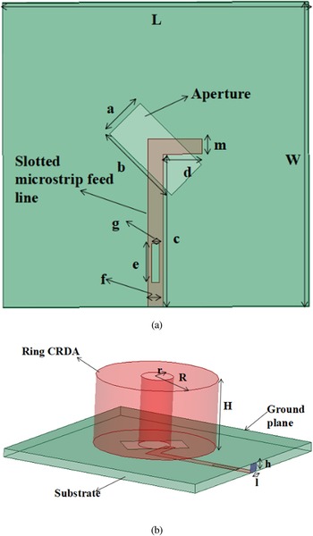
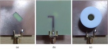
The geometry of the proposed ring CDRA of overall size L × W mm2 is shown in Fig. 1. Inverted rectangular (tilted rectangular) shaped aperture (a × b mm2) has been etched on the top of the substrate (FR-4: ɛrsub = 4.4, tan δ = 0.02 and height = 1.6 mm) and an inverted L-shaped slotted (slot length e = 5.25 mm and width g = 1 mm) microstrip feed line (feed length c = 20 mm and width f = 2 mm) is designed below the substrate as shown in Fig. 1(a). The ring CDRA (Alumina: ɛr = 9.8, tan δ = 0.002) of height of 12.75 mm having inner radius of 3 mm and outer radius of 11 mm is positioned on the substrate with the help of adhesive material as shown in Fig. 1(b). The fabricated prototype of the proposed ring CDRA is shown in Fig. 2. The details of optimized parameters are shown in Table 1.
(a) Systematic diagram of proposed ring CDRA. (b) Feeding structure in isometric view.

Fabricated prototype of proposed ring CDRA. (a) Top view without ring CDRA. (b) Feeding structure. (c) Top view with ring CDRA.

Optimized parameters of the proposed ring CDRA.

Working of proposed ring CDRA
Ansys HFSS simulator is used to analyze the working of the proposed ring CDRA. The proposed ring CDRA is simulated between frequency ranges 6–13 GHz. The working of the proposed ring CDRA is divided into two sub-sections: (i) Return loss |S11| and (ii) CP wave analysis. Besides stepwise design, the return loss |S11| analysis was carried out to observe the effect on impedance bandwidth in terms of ring CDRA (without DRA, with CDRA, with ring CDRA and variation in radius of ring CDRA), microstrip feed line (without slotted, with slotted and slot length variation) and position of rectangular-shaped aperture (angle variation of tilted rectangular aperture) whereas CP wave analysis carried out to observed the effect on AR bandwidth in terms of microstrip feed line (slot length variation) and position of rectangular-shaped aperture (angle variation of tilted rectangular aperture).
Return loss |S11| analysis
A stepwise design procedure of the proposed ring CDRA is shown in Fig. 3 and the commensurate |S11| graph for each step are shown in Fig. 4. It is clear from Fig. 4, that in step-1, ring CDRA is resonating as a multiband antenna due to two rhombus-shaped apertures and a simple rectangular microstrip feed line. In step-2, ring CDRA is resonating as a dual-band antenna due to an inverted rectangular (tilted rectangular) shaped aperture and simple rectangular microstrip feed line. In step-3 and step-4, the antenna is resonated nearly the same frequency range, but bandwidth enhancement in step-4 is due to the slotted microstrip feed line.
Stepwise design of proposed ring CDRA.

Change in |S11| graph with step to step design procedure.

Effect of ring CDRA
The |S11| graph of without DRA, with CDRA and with ring CDRA is shown in Fig. 5. It is confirmed from Fig. 5 that the proposed ring CDRA is a hybrid radiator because the resonating band is due to with and without DRA. The ring CDRA has better bandwidth than CDRA (without ring) due to removing the central portion of ceramic material. (Decreasing the Q-factor and increasing the impedance bandwidth) [Reference Sharma, Ranjan and Sikandar24]. The antenna is resonating in dual-band with and without DRA while in wideband with ring CDRA.
Comparison of |S11| graph without DRA, with CDRA and with ring CDRA.

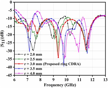
The |S11| graph variation after changing the radius (r) of ring CDRA is shown in Fig. 6. It is confirmed from Fig. 6 that the |S11| graph of the proposed ring CDRA at radius r = 3 mm is better in terms of impedance bandwidth. Besides radius r = 3 mm, the antenna is resonating in a dual band at radius r = 2 mm, r = 2.5 mm and r = 3.5 mm while resonating in a triple band at radius r = 4 mm.
Comparison of |S11| graph after changing the radius of ring CDRA.

Effect of the slotted feed line
Figure 7 represents the |S11| graph with slotted microstrip feed line (slot length e = 5.25 mm and width g = 1 mm) and without slotted microstrip feed. It is clear from Fig. 7, that the proposed ring CDRA with slotted microstrip feed line is resonating below −10 dB line between 6.08 and 12.2 GHz frequency band, but in case of without slotted microstrip feed line, some part in the given frequency band (6.08–12.2 GHz) is resonating above the −10 dB line. Thus, the proposed ring CDRA with slotted microstrip feed line has better impedance bandwidth because of providing good coupling between antenna and feed line [Reference Zebiri, Benabelaziz, Lashab, Sayad, Elmegri, Elfergani, Ali, Hussaini, Abd-Alhameed and Rodriguez25, Reference Shivnarayan and Vishvakarma26].
Comparison of |S11| graph with and without slotted microstrip line feed.

The variation of |S11| graph after changing the slot length (e) is shown in Fig. 8. The variation in slot length is observed at different values of slot length between e = 4.25 mm to e = 5.75 mm. It is clear from Fig. 8, that the proposed ring CDRA is optimal at e = 5.25 mm with a small improvement in impedance bandwidth while a large effect is observed in AR bandwidth.
Comparison of |S11| graph after changing the length of the slot.

Effect of the tilted rectangular (inverted rectangular shaped) aperture
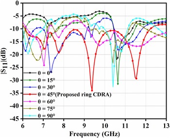
Figure 9 represents the changing position of a rectangular-shaped aperture with an angle (θ) and its commensurate |S11| graph is depicted in Fig. 10. It is confirmed from Fig. 10 that the proposed ring CDRA at θ = 45° is resonating below −10 dB line with wideband impedance bandwidth in the frequency band 6.08–12.2 GHz while the antenna is resonating in multiband for other angles except θ = 45°. Thus, the impedance bandwidth of the proposed ring CDRA at θ = 45° is better than other angles.
Position of rectangular (tilted) shaped aperture at a different angle (θ).

The variation of |S11| graph at different position of rectangular-shaped aperture.

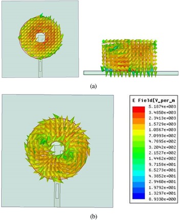
E-field distribution inside the ring CDRA at frequencies 6.4 and 11.5 GHz is shown in Fig. 11. It is confirmed from Fig. 11(a) that HEM11δ mode is generated at frequency 6.4 GHz whereas Fig. 11(b) shows the generation of a higher HEM12δ mode at frequency 11.5 GHz [Reference Kajfez, Glisson and James27]. The HEM11δ mode is a fundamental mode in ring CDRA which shows one full wave variation in the azimuthal direction and one half-wave variation in a radial direction. Similarly, HEM12δ mode shows one full wave variation in the azimuthal direction and two half-wave variation in a radial direction. In both modes, “δ” shows the variation in an axial direction and its values lies between 0 and 1 [Reference Petosa1, Reference Mongia and Bhartia28]. In the dielectric waveguide, the boundary condition is not perfect compared to the metallic waveguide, so the field line cannot rotate completely and the direction of propagation is neither completely zero nor one [Reference Kumar and Chaudhary16].
The distribution of E-field in ring CDRA. (a) Top view and side view at 6.4 GHz. (b) Top view at 11.5 GHz.

The generated modes can also verify by using the following mathematical formulas [Reference Mongia and Bhartia28, Reference Sharma, Das and Gangwar29].

We can calculate the fr HEM12δ with the help of fr HEM11δ:

where, r = internal radius of ring dielectric resonator and H = height of ring dielectric resonator.

where,

From equations (1) and (2), the resonating frequency of mode HEM11δ is found 6.4 GHz while for mode HEM12δ it is found 11.5 GHz.
Circular wave (CP) analysis
Figure 3 represents the step by step design procedure and its corresponding AR versus frequency graph is shown in Fig. 12. The essential condition for the creation of CP wave; two field components are equal in magnitude and orthogonal to each other [Reference Kumar and Chaudhary14]. It is clearly observed from Fig. 12, that the CP wave is not generated in step-1 and step-2. The tilted rectangular shaped aperture and inverted L-shaped microstrip feed line are responsible for generating CP waves in steps-3 and step-4 with AR bandwidth of 2.13% (230 MHz) and 6.99% (780 MHz) respectively. In the proposed ring CDRA, tilted rectangular shaped slot behaves as a magnetic dipole and is also used to maintain the equal amplitude of the fields [Reference Almpanis, Fumeaux and Vahldieck30]. The inverted L-shaped feed line acts as an electric dipole and provides the phase difference (90°) between the fields [Reference Sharma, Das and Gangwar29]. Thus, the tilted rectangular shaped aperture and inverted L-shaped microstrip feed line are used to generate CP wave. However, the enhancement of AR bandwidth in step-4 is due to the slotted microstrip feed line (strong coupling between antenna and feed line) [Reference Zebiri, Benabelaziz, Lashab, Sayad, Elmegri, Elfergani, Ali, Hussaini, Abd-Alhameed and Rodriguez25, Reference Shivnarayan and Vishvakarma26].
Generation of circular wave with step to step design procedure.

The variation of AR bandwidth with changing the slot length of the microstrip feed line between e = 4.25 mm to e = 5.75 mm is shown in Fig. 13. It is confirmed from Fig. 13, that the optimized value of slot length is observed at e = 5.25 mm for maximum AR bandwidth 6.99% (780 MHz) compared to e = 4.25 mm (450 MHz) and e = 4.75 mm (390 MHz) while no AR bandwidth is obtained for e = 5.75 mm.
Comparison of AR graph after altering slot length.

The position of tilted rectangular shaped aperture is changed at a different angle (θ) between θ = 0° and θ = 90° as shown in Fig. 9 and its corresponding AR versus frequency graph is depicted in Fig. 14. It is confirmed from Fig. 14 that the AR graph only for angles θ = 45°, θ = 60° and θ = 75° are resonating below 3 dB AR line, but the 3 dB AR bandwidth 6.99% (780 MHz) of the proposed ring CDRA at angle θ = 45° is better than angle θ = 60° (450 MHz) and θ = 75° (160 MHz). The rectangular (tilted) shaped aperture is used for maintaining the equal amplitude of two fields [Reference Almpanis, Fumeaux and Vahldieck30].
The variation of AR graph after changing the position of rectangular-shaped aperture with angle (θ).

Results discussion and experimental validation
The experimental outcomes are compared with the simulated results for verifying the design of the proposed radiator with help of a prototype antenna as shown in Fig. 2. Vector network analyzer (Agilent Technologies E5071C) is used to measure the proposed radiator's return loss |S11| graph. A comparison of measured and simulated |S11| graph is shown in Fig. 15. The return loss |S11| graphs are almost the same. Some changes in the return loss |S11| graph take place because of the use of gluey materials for the placing of ring CDRA above the substrate [Reference Sharma, Das and Gangwar31]. The experimental return loss |S11| graph shows that the proposed radiator is resonating between 6.14 and 12.32 GHz with 66.95% (6180 MHz) impedance bandwidth whereas simulated antenna also shows 66.95% impedance bandwidth but resonating between 6.08 and 12.2 GHz (6120 MHz).
Comparison measured and simulated of |S11| graph.

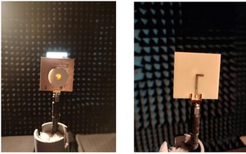
The anechoic chamber as shown in Fig. 16 is used to measure the far-field pattern of the proposed ring CDRA, where the CP horn antenna is used as a reference antenna. The comparison of AR graphs between measured and simulated is shown in Fig. 17. The dual pattern measurement method is used to measure the AR [Reference Stutzman and Garg32]. A good similarity is achieved between measured and simulated AR graphs. The simulated 3 dB AR bandwidth is obtained 6.99% (780 MHz) between the frequency ranges of 10.76–11.54 GHz whereas the experimental result shows that the proposed radiator is resonating between 10.9 and 11.5 GHz with a 5.36% (600 MHz) AR bandwidth. The minimum AR value of 0.2 and 1.36 dB is obtained for the simulated and measured antenna at 11 and 11.2 GHz respectively.
Image of measurement set up in an anechoic chamber.

Comparison of measured and simulated AR graph.

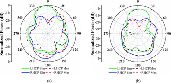
Measured and simulated LHCP (left hand circularly polarized) and RHCP (right hand circularly polarized) pattern in broadside direction at θ = 0, ϕ = 0 and θ = 0, ϕ = 90 are shown in Figs 18(a) and 18(b) respectively at frequency 11 GHz. It is clear from Fig. 18 that the proposed ring CDRA exhibits an LHCP pattern with 20 dB difference between LHCP and RHCP patterns and a good similarity between measured and simulated results is observed. The radiation pattern can be improved by reducing the thickness of the substrate [Reference Nguyen, Tran and Nguyen-Trong33], but after decreasing the thickness of the substrate, bandwidth also decreases [Reference Schaubert, Pozar and Adrian34]. The radiation pattern of the horizontal (E H) and vertical plane (E V) is used to measure the LHCP and RHCP pattern of the proposed ring CDRA [Reference Sharma, Das and Gangwar35].


LHCP/RHCP pattern of proposed ring CDRA at 11 GHz for (a) θ = 0, ϕ = 0, (b) θ = 0, ϕ = 90.

The measured and simulated gain in the broadside direction (at θ = 0, ϕ = 0) is shown in Fig. 19. A good similarity is seen between a measured and simulated gain of the proposed ring CDRA. It is observed from Fig. 19 that the highest gain value of 9.02 dBic is obtained at 7.6 GHz while the peak gain value of 5.7 and 5.4 dBic is obtained at resonating peaks 9.4 and 11.5 GHz respectively. However, 5.08 dBic peak gain is obtained at 11 GHz in the AR band. It is clear from Fig. 5 that the lower part of the frequency band is due to CDRA but the upper half portion is due to the combining effect of inverted rectangular shaped (tilted) aperture and ring CDRA. Thus, the gain is not constant and decreasing at the upper portion of the frequency band due to metallic loss [Reference Sharma, Das and Gangwar35].
Comparison of measured and simulated gain.

Table 2 represents the comparison of the proposed ring CDRA with previous published wideband DRA based on the size of the antenna, no. of DRA used, feeding method, impedance bandwidth, AR bandwidth and peak gain whereas bar graph shown in Fig. 20 represents a comparison of impedance and AR bandwidth. It is confirmed from Table 2 and Fig. 20 that the proposed ring CDRA has numerous advantages such as simple in design (small structure and single DRA is used), large impedance bandwidth (6120 MHz) and high peak gain (9.02 dB) as compared to reported papers but the AR (780 MHz) is less only compared to single-band antennas [Reference Fakhte, Oraizi, Karimian and Fakhte8] (1300 MHz) and [Reference Kumar and Chaudhary16] (1290 MHz). However, their impedance BW is narrow (2100 and 1580 MHz) compared to the proposed ring CDRA and they also used two DRA. The size of antennas represented in [Reference Fakhte, Oraizi, Karimian and Fakhte8, Reference Chaudhary, Kumar and Srivastava9, Reference Bezerra, Sousa, Junqueira, Silva, Barroso and Sombra11, Reference Tsai, Deng, Chen and Liu15, Reference Chauthaiwale, Chaudhary and Srivastava17] is also large compared to proposed ring CDRA whereas proposed ring CDRA is superior in terms of peak gain compared to previous published wideband DRA shown in Table 2.
Bandwidth comparison of proposed ring CDRA with reported work.

Comparison of proposed ring CDRA with previous published wideband DRA.

NR: not reported.
Conclusion
In this article, a circularly polarized ring CDRA of wideband impedance bandwidth has been presented. The proposed ring CDRA provides two hybrid modes HEM11δ and HEM12δ resonating between frequency band 6.08–12.2 GHz with 66.95% (6120 MHz) impedance bandwidth. The AR bandwidth is obtained at 6.99% (780 MHz) with a minimum AR value of 0.2 dB at frequency 11 GHz between the frequency ranges of 10.76–11.54 GHz. The use of inverted rectangular (tilted rectangular) shaped aperture and inverted L-shaped microstrip feed line generates two-hybrid mode HEM11δ and HEM12δ while ring CDRA and slotted microstrip feed line are responsible for the enhancement of impedance bandwidth. The proposed ring CDRA shows a peak gain of 9.02 dBic at 7.6 GHz whereas 5.08 dBic peak gain is obtained at 11 GHz in the AR band. The resonating band of a proposed radiator is useful for different applications in X-band.
Data availability statement
Data sharing not applicable – no new data generated.
Conflict of interest
The author declares no potential conflict of interest.
 Chandravilash Rai is currently working as a research scholar in the Department of Electronics & Communication Engineering, Indian Institute of Information Technology Allahabad, Prayagraj, U.P (India). In 2009, he received his B. Tech Degree in electronics and communication engineering from the UPTU, Lucknow, and completed M.Tech in digital communication engineering from Rajiv Gandhi Proudyogiki Vishwavidyalaya, University in Bhopal, Madhya Pradesh, India, in 2017. His research interests include RF and microwave, dielectric resonator antenna, microstrip patch antennas, wireless communication and antenna theory.
 Dr. Sanjai Singh received his Ph.D. degree from the University of Allahabad, India. Currently, he is an associate professor at the Electronics and Communication Engineering Department at the Indian Institute of Information Technology, Allahabad, India. His research interests are modern physics, semiconductor devices, wave theory, antenna theory.
 Dr. Ashutosh Kumar Singh received his M. Tech. degree from MNNIT Allahabad and a Doctoral degree from the Indian Institute of Information Technology, Allahabad, India. Currently, he is an assistant professor at the Electronics and Communication Engineering Department at the Indian Institute of Information Technology, Allahabad, India. His research interests include control systems, electronic circuits, networked control systems, and practical applications of control system theory, antenna theory.
 Ramesh Kumar Verma is born on 15, June 1985 in Ambedkar Nagar, Uttar Pradesh India. He is currently pursuing Ph.D from AKTU Lucknow, Uttar Pradesh India. He had completed M.Tech in the year 2015 from Bundelkhand Institute of Engineering and Technology Jhansi, in digital communication. He had completed B.Tech in the year 2009 from Raj Kumar Goel Institute of Technology Ghaziabad in electronics and communication engineering. He is an expert in antenna designing, fabrication, IE3D simulation software and particle swarm optimization (PSO) algorithm. Presently he is working on optimization of microstrip patch antenna with PSO and curve fitting.