


1. Introduction
In 1947, in Oklahoma, USA, the first electromechanical (EM) cable-suspended drill, the ‘Electrodrill’ designed by Armais Arutunoff (1893–1978), Reda Pump Co. of Bartlesville, was tested in sedimentary rocks. The test resulted in a number of wells being drilled to as deep as ∼400m. The main feature of this technology was that it used an armored cable with a winch instead of a pipe-string to provide power and retrieve the downhole unit. Due to the insufficient power and low weight on the drill bit produced by the Electrodrill, penetration rates did not exceed 4.2 m h−1. The friction anti-torque system also caused numerous accidents, with borehole wall collapse and drill sticking resulting in the termination of these activities.
In the 1940s-50s, pipeless drilling technology was also developed in the Soviet Union (Reference Minin, Pogarskyi and ChefranovMinin and others, 1956). To equilibrate counter-torque, the drill bit was rotated alternately in both directions to a certain prescribed rate, and the torque of the drill bit was balanced by the inertia of the EM drill housing. This project was also terminated as the hole-making capability achieved was low.
In 1964, Arutunoff’s Electrodrill was modified by the US Army Cold Regions Research and Engineering Laboratory (CRREL) for glacial research (Reference Ueda and GarfieldUeda and Garfield, 1968). In 1966, this drill was used for coring at Camp Century to the bottom of the Greenland ice sheet, 1387.5 m from the surface, and penetrated subglacial rocks to 3.5 m depth. This was a turning point in ice-drilling technology.
Since implementation of the first CRREL drill, many concepts of shallow and deep EM drills have been designed. Use of EM cable allows significant reductions in power and material consumption, faster tripping operations and easier cleaning of the borehole from cuttings. The cuttings are removed to the downhole chamber within the drill either by an auger conveyer in so-called shallow drills or fluid circulation and filtering.
Although some attempts were made to minimize counter-torque (e.g. using double rotation core barrels as suggested by Reference WehrleWehrle, 1985), the special device usually called an ‘anti-torque system’ has to be considered as a means of preventing spinning of the upper non-rotated part of the drill. At the same time, the anti-torque system should allow the drill to move up and down during both drilling and tripping operations. Usually the anti-torque system has a blade form of various designs that can engage with the borehole wall and hold the torque from the stator of the driving electric motor. The design of an anti-torque system is of prime importance because failure of this system leads to spinning of the cable termination and twisting of the cable in the case of slip-ring and swivel absence. Thus, some drills include an anti-torque system failure alarm that helps the operator to stop penetration if the upper part of the drill begins to rotate.
As the properties of snow, firn, ice and subglacial rocks are quite different, anti-torque systems should have different parameters for maximal holding torque and axial resistance force. This is particularly important for drilling through debris-containing ice and subglacial bedrock because downhole torque and required weight on the drill bit increase in these formations by an order of magnitude.
Currently used anti-torque systems can be divided into five types (Fig. 1): (1) hinged friction blades, (2) leaf spring system, (3) skate system, (4) side milling cutters and (5) U-shaped blade system. To ensure holding of the varied counter-torque, it has been suggested that some combination of these anti-torque systems be used (e.g. leaf spring and skate systems all in one).
Types of anti-torque systems: (a) hinged friction blades; (b) leaf spring system; (c) skates; (d) side milling cutters; (e) U-shaped blade system.

Leaf spring and skate anti-torque systems have proven the most reliable designs. Both systems can hold torque high enough for drilling not only in ice but also in subglacial bedrock. Nevertheless, in certain circumstances (alternating firn/ice layers, strong ice formations, warm ice) these systems can fail. Thus it is critically important to study the operational process in order to optimize the parameters of anti-torque systems.
2. Anti-Torque System Options
2.1. Hinged friction blades
On the first CRREL EM drill, the anti-torque system consisted of hinged friction blades which are designed to be thrown out against the borehole wall upon starting the drill motor (Fig. 1a). During deep drilling at Camp Century in 1966 it was discovered that the anti-torque skates would not grab. Without an operational anti-torque system, only the large-diameter (25.4 mm) EM cable was left to provide counter-torque (Reference Ueda and GarfieldUeda and Garfield, 1968). The drilling process was controlled as carefully as possible because if there was too much weight on the bit, the cable would wind up and the drill would rise from the bottom of the borehole (personal communication from H. Ueda, 2014). This technique of torque reaction was used throughout the remainder of the drilling even in subglacial rocks. Later at Byrd Station, West Antarctica, in 1967–68 (Reference Ueda and GarfieldUeda and Garfield, 1969) additional restraint was provided by two leaf springs installed outside of the blades (Fig. 2). In further ice drilling, this type of anti-torque system was never used as the efficiency of hinged friction blades is quite low, simply because the coefficient of friction between metal and ice is small, and maximal holding torque is not enough to compensate for the counter-torque.
Anti-torque system with hinged friction blades and leaf springs of CRREL EM drill. (Photo by H. Ueda, CRREL.)

2.2. Leaf spring anti-torque system
The use of the leaf springs as centralizers for casing and different borehole-surveying apparatus is well understood. Leaf spring anti-torque systems contain three or four pre-bent leaf springs, each supported at the ends by hinges and mounted along the drill housing (Figs 1b and 3). In the borehole, leaf springs are elastically deformed and pressed against the borehole wall. Leaf spring anti-torque systems have been used in many EM drills (Table 1) as they have the following advantages: (1) mechanically, they are very simple; (2) the rise of the springs, and thereby the pressure exerted on the borehole wall, can easily be adjusted by changing the distance between the hinges; (3) the springs are flexible, allowing easy passage over any irregularities in the borehole; and (4) the leaf springs can be located outside of any non-rotated parts of the drill, resulting in a reduction in the overall length of the drill. Most anti-torque springs are in the shape of a fourth-order parabola based on Reference ReehReeh’s (1984) calculations. This produces a spring shape that offers the most efficient and uniform loading on the borehole wall.
Leaf spring anti-torque system of ISTUK EM drill (Reference Gundestrup, Johnsen and ReehGundestrup and others, 1984).

Parameters of the leaf spring anti-torque systems used for EM ice-coring drills

The anti-torque system of the PICO-5.2-inch EM drill consisted of two sets of leaf springs, each containing six leaves (Reference WumkesWumkes, 1994). It was found that springs worked so well that full-load motor current could be restrained by this system while allowing free movement of the drill up and down the borehole (it must be noted that the PICO-5.2-inch is the heaviest drill, weighing 625 kg). An additional set of anti-torque springs was added to the drill to meet the extra torque requirements when taking subglacial samples. Two sets of leaf springs can provide a relatively large holding torque, but, at the same time, can significantly increase moving resistance during drill tripping and drilling operations.
2.3. Skate anti-torque system
Skate anti-torque systems contain three or four skates (shoes) with one or two blades, which are pushed towards the borehole wall, cut in and hold the counter-torque (Figs 1c and 4). If this system is equipped with a spring pressure mechanism, it can be considered a self-adaptive design and can pass through irregularities in the borehole. Skate anti-torque systems are widely used in EM drills, but the mechanical structure varies from drill to drill (Table 2).
Skate anti-torque system of KEMS EM drill (initial option).

Parameters of the skate anti-torque systems used for EM ice-coring drills
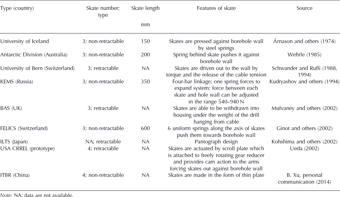
Serious shortcomings of skate anti-torque systems were exposed during drilling in firn because the skates did not hold firmly enough (Reference Árnason, Björnsson and TheodórssonÁrnason and others, 1974). High torque while drilling in ice can also cause difficulties with this system in the borehole. In the course of the Eurocore drilling (Greenland) the skate anti-torque system often started to rotate at depths below 130 m where downhole torque was unusually high (Reference Schwander and RufliSchwander and Rufli, 1994). The reaming action of the anti-torque system produced additional chips that fell down between the drill and the wall of the borehole, leading to higher torque at the motor. Similar problems were met in the course of shallow ice-core drilling in the Southern Patagonia Icefield (Reference Kohshima, Shiraiwa, Godoi, Kubota, Takeuchi and ShinboriKohshima and others, 2002). The skate anti-torque system caused problems during penetration through horizons composed of different densities, i.e. melt-frozen layers and water-soaked layers. At these horizons, the anti-torque mechanism slipped many times and drilling was often difficult. At the same time, the skate anti-torque system of the KEMS EM drill worked well even in the basal ice and in subglacial rocks where downhole torque significantly increased (Reference Vasiliev and TalalayVasiliev and Talalay, 2010). This implies that it is of great importance for this type of anti-torque system to choose the correct working parameters: optimal radial force, skate length and blade form.
2.4. Side milling cutters
Side milling cutters are mounted on both sides of the drill and form four longitudinal grooves on the borehole wall (Reference SuzukiSuzuki, 1979, Reference Suzuki1984; Figs 1d and 5). To hold the counter-torque, the guide fins are aligned with the grooves. A milling cutter anti-torque system can provide sufficient holding torque, but this type of anti-torque system must move along the already formed grooves each time, lowering and lifting the drill. If the anti-torque system is misaligned, the drill is likely to become stuck in the borehole. To release a misaligned drill it was suggested that freewheeling safety cutters be installed behind the guide fins to cut new grooves when the drill is pulled up. Ice cuttings produced by milling cutters can accumulate in the clearance between the drill and the wall, which might cause stuck drill accidents. A milling cutter anti-torque system is not adapted to the borehole with casing. When the drill passes through the casing into the ice borehole it is practically impossible to find the former grooves. Taking into account that side milling cutters gave many problems when drilling in ice, they are now considered impractical.
Mechanism of side cutters (Reference SuzukiSuzuki, 1984).

2.5. U-shaped blade system
Reference Zagorodnov, Thompson and Mosley-ThompsonZagorodnov and others (2000) promoted a new type of U-shaped blade anti-torque system consisting of two or three U-shaped stainless spring steel plates (Figs 1e and 6). The central part of the steel plates is fixed to the upper non-rotating part of the drill; the outer diameter (o.d.) of the blades is larger than the borehole diameter. In the borehole, spring plates produce force against the borehole wall and blades are inevitably engaged into the borehole wall. Since the cutting angle between the working steel plate and the borehole wall is <90°, when the drill rotates, the blades cut deeper into the borehole wall, providing sufficient holding torque. Testing of this anti-torque system on Sajama ice cap, Bolivia, in July 1997 showed that the thin (0.2 mm) blades were bent almost every drilling run. Thicker blades (0.38 mm) were used for the next drillings on Dasuopu glacier, China, in September 1997, and the Raven (former Dye 2) site, southern Greenland, in May 1998. It was found that in layered firn–ice sequences thicker U-shaped blades offered substantial resistance when the drill was lowered into the borehole.
U-shaped blade system of V. Zagorodnov’s design (Reference Zagorodnov, Thompson and Mosley-ThompsonZagorodnov and others, 2000).

The next version of the three U-shaped blade system was free of this major drawback. The working blade edges were reinforced and never bend in the borehole (personal communication from V. Zagorodnov, 2014). The axial static friction was less than 20N and far less during drilling or lowering. A few sets of blades could provide at least 200 Nm holding torque.
2.6. Combined anti-torque system
Combined anti-torque systems are intended to work in formations with different mechanical properties (e.g. in loose firn as well as hard ice). To accomplish this, two independent systems are normally used. Reference Rufli, Stauffer, Oeschger and SplettstoesserRufli and others (1976) suggested using a four-skate anti-torque system that is effective in hard firn or ice, but in the soft firn a two-plate leaf springs anti-torque system was added to provide additional restraint (Fig. 7). The skate anti-torque system is retracted during lowering or raising of the drill, and presses against the borehole wall as soon as the drill reaches the bottom of the borehole, while the second device presses against the borehole wall at all times. Reference HoldsworthHoldsworth (1984) suggested using a leaf springs anti-torque system with small skates fixed to the exterior side of the leaves (Fig. 8). The idea of this design was to reduce the ‘edge effect’ of the leaf spring when drilling in snow/ice transition layers.
Combined anti-torque system suggested by Reference Rufli, Stauffer, Oeschger and SplettstoesserRufli and others (1976).

Leaf-spring/skate anti-torque system (Reference HoldsworthHoldsworth, 1984).

3. Required Parameters of Anti-Torque System
To ensure a reliable torque reaction of the EM drill, the anti-torque system should meet two requirements: provide adequate counter-torque, and allow the drill to move up and down in the course of tripping operations and drilling. Hence, the main parameters of anti-torque systems are (Fig. 9): (1) maximum holding torque, M max, that specifies conditions at which blades (leaf springs or skates) start to cut the borehole wall, resulting in anti-torque failure, and (2) maximum axial resistance, F a, of the blades that has as slight as possible an effect on the speed of the drill’s lowering/hoisting.
Schematic of torques and forces on EM drill with single core barrel.

The holding torque of the anti-torque system depends on the radial force, F r, that causes the blades to penetrate the borehole wall. It is evident that the blade’s depth of penetration and the maximal holding torque will increase with increasing radial force. At the same time, increasing the radial force will eventually lead to raising the axial resistance of the anti-torque system while the drill moves up and down the borehole. Therefore, the main task of anti-torque system design is to develop the structure with adequate radial force against the borehole wall and to find a reasonable balance between the maximum holding torque and the axial resistance.
3.1. Maximum holding torque
The maximum holding torque should be higher than the counter-torque produced by the downhole driving unit (motor) while drilling: M max>M ct. Considering the safety factor, k s, that applies to emergency situations (e.g. unexpected loads, irregularities of the borehole shaft, cuttings packing, misalignment between core barrel and drive unit, etc.), we obtain

The choice of safety factor (typically in the range 1.5–4) is based on several considerations, such as the accuracy of predictions of the torque, the consequences of engineering failure, and the cost of over-engineering the component to achieve that safety factor. We suggest using the safety factor of 2 that is usually applied in construction and drilling engineering.
The total counter-torque produced by the downhole electric motor is summarized from two main torque sources (Fig. 9): torque on the drill bit for ice (bedrock) cutting, M db, and torque to rotate the core barrel in the fluid, M cb. Thus, the total counter-torque is estimated according to

The torque on the drill bit for ice cutting can be estimated using the specific energy consumed per unit volume of cutting, E S (N m−2; modified from Reference TalalayTalalay, 2003):

where ROP is the rate of penetration (m h−1), n is the drill bit rotation speed (rpm) and D db and d db are the drill bit o.d. and inner diameter (i.d.) (m).
According to Reference Ueda and KalafutUeda and Kalafut (1989), the specific energy values ranged from 0.54 to 6.4 MN m–2 depending on the cutting parameters. At a cutting depth of 2.54 mm and a cutting velocity of 0.26 ms−1 the specific energy was 0.9-3.2 MN m–2 if cutters with 30° rake angle were used.
The torque on the drill bit for rock drilling is usually calculated using various empirical equations, for example (modified from Reference Shamshev, Tarakanov, Kudryashov, Paryisky and YakovlevShamshev and others, 1983):

while drilling with tungsten-carbide drill bits, and

while drilling with diamond drill bits, where WOB is the weight on the bit (N), and μ is the coefficient of friction of carbide inserts on the rock down the borehole (0.15–0.2 for argillaceous slate; 0.3–0.4 for limestone and sandstone).
Since the core barrel is rotated in a drilling fluid, it will generate additional torque that can be calculated according to

where
 is the force at the ith surface of the core barrel resulting from the rotation in a liquid (special aspects of hydraulic force estimations are described by Reference TalalayTalalay, 2003) and Ri
(m) is the rotation radius of this surface.
KEMS and DISC EM drills use a single core barrel, and the flow goes from the pump into the space between the drill and the borehole wall to the bottom of the drill (the case shown in Fig. 9). Passing through the openings in the drill head, the liquid picks up the cuttings and then flows upward between the core and inner surface of the core barrel. In this instance, hydraulic friction on both the outer and inner surfaces of the rotating core barrel should be taken into account. In the case of the non-rotated outer barrel and rotated inner barrel (JARE and Hans Tausen drills) the friction between outer and inner barrels is compensated internally.
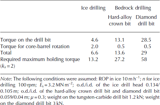
After defining all the counter-torque factors, we can select the anti-torque system that can hold the torque produced while drilling. As an example, the required maximum holding torque is calculated according to Eqns (1–6) for drilling in ice with a 7 m long single core barrel combined with the chip chamber and for rock drilling with a 4 m long core barrel (Table 3). The required maximum holding torque for drilling in ice is estimated at 13.2 Nm, roughly four times less than the required holding torque for drilling in bedrock.
Estimates of the counter-torque (Nm) produced by EM drills
3.2. Axial resistance during drill tripping
Axial resistance F a is produced by friction and cutting action while blades skate along the borehole wall. During lowering and drilling, gravity is primarily used to move the drill in the borehole, and high axial resistance of the anti-torque system would have the undesirable effects of slowing tripping time in the borehole and impeding penetration. Reference Onishin, Blinov, Vartikayan and PlavskiyOnishin and others (1990) studied the simple lowering of a wire-line drilling tool without considering resistance caused by the hoisting winch, etc., and recommended the following equation for steady movement in case of laminar flow between drill and borehole wall (the equation is modified by adding axial resistance force F a (N) for every contacted element of the anti-torque system):

where v l is the free drill’s lowering rate in the borehole (ms−1), g is gravitational acceleration (9.81 ms–2), k 1 is the ratio of the drill diameter d to the borehole diameter D, v is the kinematic viscosity of fluid (m2s−1), ρ fl is the density of fluid (kg m–3), m is drill mass (kg), l is drill length (m) and q is the number of anti-torque elements in contact with the borehole wall.
It should be noted that this equation works for

and the drill’s lowering rate in the borehole is linearly dependent on the axial resistance force of the anti-torque system. For example, F a = 100N will lead to a decrease in the drill’s (d/D = 127/134 mm; m = 180-200 kg) lowering rate of 12-16% in the common drilling fluid (ν = 5 mm2 s−1; ρ fl = 930 kg m–3) compared with the retractable anti-torque system. This eventually increases the overall time and cost of the whole drilling project.
To achieve a higher free lowering rate it would be possible to add the dead weights, but this would add to the drill/tower length and significantly increase the hoisting winch’s power consumption. The other option considers the retractable design of the anti-torque system when contacted elements (leaf springs or skates) are able to be withdrawn into the drill body during tripping operations.
3.3. Axial resistance during drilling
For the drill’s smooth movement during penetration, the drill weight must be sufficient to maintain the required weight on the bit:

or

where F c is cable tension (N) at the drill’s termination and k d is the de-loading coefficient which defines the ratio between the cable tension and the weight of the drill (to ensure the hole-straightening k d>0.5 if the drill’s center of gravity coincides with the geometric center).
The rearrangement gives the constraint for the maximum axial resistance of the anti-torque system during drilling:

While drilling ice, the smooth drill movement during penetration creates no difficulties as WOB is quite low (75–100 N; Reference TalalayTalalay, 2003). Assuming m = 120 kg, k d = 0.6 and q = 3, the axial resistance of each blade should be <123N. When drilling bedrock, the required WOB increases to 3 kN or more (Reference CaoCao and others, 2014). To create such a high load, the most viable option is to add the dead weights to the drill. Assuming in this case m = 420 kg, k d = 0.1 and q = 3; the axial resistance of the each blade should be <235N.
4. Testing Of Anti-Torque Systems
4.1. Testing stand
The testing stand was designed and produced to evaluate performance of the different anti-torque systems by measuring maximum holding torque and axial resistance force. The anti-torque system testing stand consists of the frame, rotary section, sliding section, ice block with the borehole, anti-torque system and instrumentation system (Fig. 10).
Anti-torque system testing stand: 1. torque sensor; 2. handle; 3. bearing assembly; 4. rotary shaft; 5. cardan joint; 6. anti-torque system; 7. ice hole; 8. temperature sensor; 9. pulley; 10. frame; 1 1 . steel rope; 12. tension sensor with pull-off device.

The anti-torque system is inserted in a borehole of appropriate length and diameter. The upper part of the anti-torque system is connected to a handle through a cardan joint, coupled rotary shaft and torque sensor. The cardan joint allows the axis to ‘bend’, thereby reducing the effect of misalignment between the anti-torque system and rotary shaft. The coupled rotary shaft consists of the upper hollow shaft, supported by two bearing assemblies, and the lower inner shaft which can slide up and down the hole in the hollow shaft and transmit rotation through slot and key.
The lower part of the anti-torque system is connected with a steel rope deflected by a pulley from axial to horizontal position, facilitating connection with the tension sensor and pull-off device of AEH type. This device provides a smooth pulling force for moving the anti-torque system with a maximal load of 1000N and speed in the range 0–500 mm min−1. The upper and lower ends of the skate anti-torque system were centered in the borehole with two Teflon rings: otherwise, the system is lopsided and provides unreliable high holding torque. Two other systems did not need to be centered.
4.2. Instrumentation
Three main parameters are measured and recorded on the computer:
Holding torque using LKN-205 torque sensor with a range 0–500 N m and measurement accuracy ±0.2%;
Axial resistance force using HP-500 load sensor with maximal load of 500 N and accuracy of 0.1 N (to measure >500N load, the weights are added to the upper part of the anti-torque system);
Ice temperature using TS401-type temperature sensor (measurement range −50 to 100°C, accuracy ±0.1°C) installed inside the ice.
All parameters are displayed in real time on the screen and stored in the PC database.
4.3. Tested anti-torque systems
The three most reliable anti-torque system designs were suggested for testing and comparison: the leaf spring, skate and U-shaped blade anti-torque systems (Fig. 11).
Tested anti-torque systems.

The leaf spring anti-torque system is of traditional design, using three curved leaf springs based on Reference ReehReeh’s (1984) calculations (Fig. 12a). The anti-torque system has an adjusting nut on the top to change the distance between two hinges of leaf spring increasing or decreasing the holding torque. Leaf springs (656 mm × 30 mm × 2 mm) are made from manganese steel. The nominal axial distance between hinges is 670 mm. Additional experiments revealed the following correlation between radial force exerted by each leaf spring and hinges distance d h (mm) (R 2 = 0.98):

The skate anti-torque system is designed as a six-bar linkage mechanism. The o.d. of skates and radial force were changed using an adjusting nut (Fig. 12b). The length of each skate is 350 mm; the taper angle of the skate blade is 20°; the stiffness of each of the three springs is 19.61 Nmm−1. In order to decrease axial resistance, the ends of the skates are rounded off. Based on the theory of mechanics, radial force exerted by each skate is directly proportional to the o.d. (simplified from Fan and others, in press):

Schematic of tested anti-torque systems: (a) Leaf spring anti-torque system: 1. adjusting nut; 2. upper hinge support; 3. screw tube; 4. leaf spring; 5. drill body; 6. driven unit; 7. lower hinge support; 8. shaft. (b) Skate anti-torque system: 1. lower joint; 2. adjusting nut; 3. spring; 4. outer tube; 5. upper support; 6. adjusting lever; 7. middle support; 8. skate; 9. lower support; 10. upper joint. (c) U-shaped anti-torque blade system: 1. body; 2. U-shaped blade; 3. hold-down; 4. bolt.

where D s is the o.d. of the skates (mm).
The U-shaped blades are made from 304 stainless spring steel plates of different thicknesses: 0.1, 0.2, 0.5 and 0.8 mm (Fig. 12c). The length of the blades is 350 or 500 mm and the ends are slightly slanted. The blade’s edges are rectangular and not sharp.
4.4. Experimental procedure
Ice was frozen in 250 mm diameter tubes with sealed removable bottoms. Two different tube heights were used: 600 and 1000 mm. The longer tube is for the leaf spring anti-torque system, the shorter for skate and U-shaped blade anti-torque systems. In the center of the ice block the hole was drilled using a vertical drill-press, a 134 mm diameter three-cutters core drill bit and air circulation to remove ice chips. The drilled hole is as vertical as possible, with a smooth wall, and the diameter is measured to 134.3 mm.
The anti-torque system being tested was inserted into the ice hole, the upper part of the anti-torque system was connected with a pin to the rotating shaft, and wire was used to connect the lower part to the tension sensor (Fig. 13). When the test stand was assembled, the handle was manually rotated with increasing force until the anti-torque system slipped. The measured torque at that moment was considered the maximum holding torque (M max). The rotation of the system was continued to measure continuous rotation torque (M cont).
Working on anti-torque system testing stand.

After the torque test, the AEH pull-off device was switched on, gradually increasing the driving-motor current until the anti-torque system started to move. The total axial resistance force (TFa) was registered and displayed in real time and stored in the computer. Pulling continued until the anti-torque system reached the bottom of the ice hole.
To investigate the lubricating effect of the drilling fluid in holding torque and axial resistance force, similar tests in a ‘dry’ borehole and in a hole filled with aviation fuel Jet A1 were carried out (only for a U-shaped blade anti-torque system).
4.5. Experimental results
Experimental tests were carried out at the Polar Research Center testing site in Changchun City during winter 2013/14. A total of 49 ice samples were used: 8 for the spring leaf system, 19 for the skate anti-torque system, 15 for the U-shaped blade system without drilling fluid and 7 for the U-shaped blade system with drilling fluid.
4.5.1. Spring anti-torque system
To study performance of the leaf springs, the distance between hinges was adjusted within the range 666–673mm, with corresponding radial force of 78–757 N against the borehole wall. Ice temperature in the simulated borehole was between –9.8 and –10.6°C, with an average of –10.2°C. M max and M cont increased with decreasing distance between hinges, with a highest torque of 99.7 and 84.2 N m, respectively (Fig. 14a). The TFa of the leaf spring anti-torque system also increased with decrease in distance between the hinges, from 19.3 N to 243.1 N (Fig. 14b).
Holding torque (a) and total axial resistance force (b) of leaf spring anti-torque system vs distance between hinges/total radial force against borehole wall.

Two forms of contact between the ice and the leaf springs became apparent: straight form if distance between the hinges is >668 mm, and waved form if distance is <668 mm (Fig. 15). In the latter case, leafs contacted against walls only in two points instead of a line. Although waved leaf springs can provide large holding torque, irreversible deformation of the leaf springs after being subjected to stress can occur; this will eventually reduce the force against the borehole wall and affect the life of the leaf springs. To provide uniform loading on the borehole wall, the distance between hinges of the tested spring anti-torque system design should be at least 668 mm, with radial force of near 560 N that can hold torque as high as 40.2 N m.
Possible leaf spring form in contact with borehole wall: (a) straight form; (b) waved form.

4.5.2. Skate anti-torque system
Test results were arranged into two groups: one with an average temperature of –9.9°C (range –9.6 to –10.1°C) and the other with an average temperature of –3.2°C (range –2.6 to –4.1°C). It was found that the skate anti-torque system performed differently in steady motion than in dynamic state when it was slightly vibrated by hand. The latter effect can be observed in an actual borehole due to axial and radial vibration of the drill. This is why two sets of experiments were carried out for this system to measure steady motion total axial resistance force (STFa) and dynamic total axial resistance force (DTFa).
Obviously, the M max, M cont, STFa and DTFa increase with the skates’ o.d. and radial force against the borehole wall (Fig. 16). In the same conditions, M max >M cont, and STFa > DTFa. M cont increases at a smaller rate with enlargement of the skates’ o.d. than M max. At –9.9°C, all measured parameters are higher than at –3.2°C temperature. The skate anti-torque system can provide M max as high as 267 N m with DTFa of 454 N.
Holding torque (a) and total axial resistance force (b) of skate anti-torque system vs skates’ o.d./total radial force against borehole wall.

4.5.3. U-shaped blade anti-torque system
Test results were arranged into two groups: one obtained at an average temperature of –10.3°C (range –9.7 to –11.5°C) and the other at an average temperature of –4.9°C (range –4.4 to –5.2°C) (Fig. 17). The holding torque of U-shaped blade anti-torque systems increases with increase in blade thickness and length, especially thickness. A U-shaped blade anti-torque system can effectively hold a torque higher than 100N m; at that torque, TFa is also high (>300N). When torque exceeded M max, the blades were deformed. After recovering the anti-torque system from the borehole, it was quite difficult to bring blades back to their original shape. Results of tests in the ‘dry’ borehole were almost the same as those in the fluid-filled borehole, which suggests that the influence of drilling fluid on the performance of the anti-torque system can be ignored.
Maximal holding torque (a) and total axial resistance force (b) of U-shaped blade anti-torque system vs blade thickness.

5. Discussion and Conclusions
To compare the performance of different anti-torque systems, the relationship between M max and TFa for each system is shown in Figure 18. The skate anti-torque system provides the highest M max, in the range 67–267 Nm, depending on the skates’ o.d. and ice temperature, while leaf springs only hold 2.5–40 N m if the springs are deformed in the regular mode. Probably this is due to (1) the larger radial force against the borehole wall produced by skates (∼1000N) than by leaf springs (<750N) and (2) the shape of blades that can more easily penetrate the walls. U-shaped blade systems can hold the torque in the range 6.5–138 N m.
Maximal holding torque vs total axial resistance force of tested anti-torque systems.

While drilling in ice, the required maximum holding torque (in our example 13.2 N m) can be firmly provided by skate systems with any tested diameters, or leaf springs with distance between hinges <670mm. As for drilling in bedrock with estimated maximum holding torque of 58 N m, the counter-torque can also be effectively compensated by skate systems but not as safely by the spring anti-torque system.
The skate anti-torque system has the largest TFa, in the range 209–454 N (while vibrating). For the leaf spring anti-torque system, TFa is far less (19–243 N). If the thickness of U-shaped blades is 0.1 or 0.2 mm, TFa is similar to that in the spring anti-torque system; if the thickness of U-shaped blades is 0.5 or 0.8 mm, TFa is close to that in the skate anti-torque system.
It was found that the different anti-torque systems scratch grooves on the borehole walls. Leaf springs contact borehole walls over a large area and scratch shallow grooves. By comparison, the contact area of skate and U-shaped blade anti-torque systems is smaller and cuts deeply into ice walls.
The leaf spring and skate anti-torque system can easily be adjusted on the surface, and during tripping operations their o.d. is self-adjusting to borehole irregularities. The working parameters of the leaf spring anti-torque system are much more sensitive to a change of distance between hinges than similar adjustment of the skate anti-torque system. To adjust parameters of the U-shaped blade anti-torque system, blades have to be changed; moreover, blades become deformed if the holding torque exceeds maximal values.
Our tests did not study the performance of anti-torque systems in snow–firn boreholes, but considering the primary performance factors (contact area, depth of penetration, radial force, and tensile strength of snow-firn formations), the leaf spring system can be considered the best option for such an environment. It is recommended that drilling in ice can be accomplished using leaf spring or skate anti-torque systems with a combination of leaf springs and skates used in interstratified firn-ice formations. The skate anti-torque system can be considered the highest-performing model in the case of subglacial bedrock drilling because it provides sufficiently high torque to hold the non-rotated part of the EM drill with acceptable axial resistance force.
Acknowledgements
Research on anti-torque systems was funded by the National Science Foundation of China (project No. 41327804), Geological Survey of China (project No. 3R212W324424) and Chinese Polar Environment Comprehensive Investigation and Assessment Programmes (CHINARE 2014-02-02 and 2014-04-02). We thank Victor Zagorodnov (The Ohio State University, USA), Oliver Alemany (LGGE, France) and Jakob Schwander (University of Bern, Switzerland) for helpful suggestions. We also thank Donald Lebar (University of Wisconsin–Madison, USA) for editing.



