I. INTRODUCTION
Welded components have been widely used in the industry. Welding, however, is a rapid heating and cooling nonequilibrium process. Some defects and welding residual stress inevitably appear in the joints due to nonhomogeneous mechanical, thermal or plastic misfits, Reference Withers and Bhadeshia1,Reference Withers and Bhadeshia2 resulting in loss of mechanical properties. Therefore, improving the quality and properties in joint surface is demanded and urgently required.
Many mechanical surface processing techniques have been reported to improve the surface mechanical properties effectively, such as surface mechanical attrition treatment, Reference Liu, Zhang and Lu3,Reference Moering, Ma, Chen, Miao, Li, Qian, Mathaudhu and Zhu4 shot peening, Reference Harding, Donaldson, Hexemer, Gharghouri and Bishop5 laser shock peening, Reference Qiao, Zhao, Zhang and Gao6,Reference Xiong, He, Guo, He, Ren and Volinsky7 and ultrasonic surface modification (USM). Reference Statnikov, Zhuravlev, Alekseev, Bobylev, Shevtsov, Sokolenko and Kulikov8–Reference Ye, Telang, Gill, Suslov, Idell, Zweiacker, Wiezorek, Zhou, Qian and Mannava10 USM dates back to 1970s and is invented by Statnikov. Reference Statnikov, Zhuravlev, Alekseev, Bobylev, Shevtsov, Sokolenko and Kulikov8 Compared with the techniques mentioned above, USM is a more effective and controllable method to enhance material properties. The USM method involves deformation treatment of the weld toe superposed by ultrasonic treatment at a frequency of 27 kHz. At beginning, USM method is used for relieving the stress concentration in ship components. It can convert the residual tensile stress into residual compressive stress, and hence to improve the performance. Reference Statnikov, Zhuravlev, Alekseev, Bobylev, Shevtsov, Sokolenko and Kulikov8,Reference Cao, Pyoun and Murakami9 Moreover, it can not only refine the surface microstructure but also improve the surface microhardness. Previous studies Reference Statnikov, Zhuravlev, Alekseev, Bobylev, Shevtsov, Sokolenko and Kulikov8–Reference Wu, Zhang, Zhang, Murakami and Pyoun11 have shown that surface nanocrystallization and severe plastic deformation (SPD) layer can be achieved on the materials surface by USM. USM is widely used to improve the fatigue life, since the residual compressive stress, surface nanocrystallization in the welded zone, and the severe deformation in the weld toe between welded seams and base materials are the main features to promote the welding joints properties. Reference Amanov, Pyun and Sasaki12–Reference Wu, Wang, Pyoun, Zhang and Murakami15 However, material strength improvement is typically accompanied by loss of ductility. The plastic loss and damages and the depth of effective layer caused by USM, which usually lead to galvanic corrosion and fatigue fracture, greatly hinder the further application of the technique. Reference Yang, Zhou and Ling16,Reference Panin, Kazachenok, Kozelskaya, Hairullin and Sinyakova17
Recently, another external field processing technique called high-energy electropulsing treatment (EPT) has been attracted interest by researchers. It is a high-energy-input technique aiming to optimize the materials microstructure, texture and to reduce deformation resistance within a short time and at low temperature. Reference Kuang, Li, Ye, Tang, Liu, Wang and Tang18–Reference Kuang, Du, Li, Yang, Luo and Tang24 EPT has also been proved to be an effective technique to heal cracks and induce damages recovery during the processing. Reference Lin, Zhao, Gao and Han25–Reference Ye, Li, Song and Tang28 Moreover, EPT is utilized for eliminating the residual stress on alloy strips. However, the size of the strip is largely limited by the ability of the electropulse current generator due to reduced eliminating rates and depth caused by decreasing current density. Reference Levitin and Loskutov29
Recently, few studies are related to the coupling of high-energy EPT and high-frequency USM, which utilizes high-energy electropulsing to improve the surface quality and assists the USM to enhance the surface properties. This coupling technique is called electropulsing assisted ultrasonic surface modification (EUSM). Surface modification, in terms of mechanical properties and biomedical functions improvements by electropulsing ultrasonic shock have obtained a preliminary basis by Ye et al. Reference Ye, Ye and Tang30–Reference Ye and Tang32 Notable enhancement of microhardness and refinement of grains are obtained during the process. Previous studies Reference Wang, Song and Tang33,Reference Liu, Li, Tang, Chen, Wang and Song34 also indicated that this technique has great potential to enhance the ductility, improve the surface mechanical properties and eliminate residual stress. Thus, EUSM is an important but elementary technology and the effect of EUSM on surface mechanical properties, microstructure evolution as well as the mechanism of electropulse in the SPD layer and surface morphology of welded components is investigated in this article.
II. EXPERIMENTAL
A. Materials and EUSM processing technique
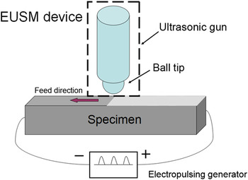
The medium carbon steel S50C was investigated as original base materials for welding components in this study. The chemical composition of the S50C steel is presented in Table I. Metal active gas welding was performed with the following welding parameters: current (170 A), voltage (22 V), welding speed (3.8 mm/s) and shielding gas (80% Ar + 20% CO2). After welding, the components are rapidly cooled in the air to obtain residual tensile stress. The thickness of the welded plates was 12 mm. The schematic diagram of the EUSM process and installation is shown in Fig. 1. High-energy electropulse current was applied at both ends of the welded components within a short time, while the ultrasonic treatment was used on the materials surface simultaneously. Three different current densities were used in the study: 1.5, 3, and 5 A/mm2. The power supply of the ultrasonic generator was 20 kW. The frequency of the ultrasonic vibration was 20 kHz. The ball tip of ultrasonic device has a diameter of 2.6 mm and is made of tungsten carbide. Each sample was treated for 20 min.
Chemical composition of the S50C steel.

Schematic diagram of the EUSM process.

B. Measuring and characterizing
The residual stress in welded joints was measured by hole drilling method on an HK21A residual stress tester. The microhardness of the welding joints were measured by using a Vickers microhardness tester (HVS-1000B, Test Instrument Co. Ltd. Laizhou Huayin, Laizhou, China) with a load of 0.98 N. Specimens for microstructure characterization were prepared by standard method and etched in 4% nital solution. The microstructure was characterized by three-dimensional optical stereomicroscope (OSM, HiROX KH-7700, HIROX Corporation, Tokyo, Japan) and scanning electron microscope (SEM, Hitachi 4800, Hitachi Limited, Tokyo, Japan).
C. Hole drilling method
Many techniques, such as x-ray diffraction and neutron diffraction, can be applied for the measurement of residual stress in components. Reference Withers, Turski, Edwards, Bouchard and Buttle35–Reference Rossini, Dassisti, Benyounis and Olabi37 X-ray diffraction and neutron diffraction can be classified as nondestructive methods. These can be classified as nondestructive methods. They usually measure the crystal lattice spacing and then obtain the strain and stress state via calculation. Reference Martins, Strohaecker, Rocha and Hirsch38 Due to their nondestructive nature, x-ray diffraction and neutron diffraction are favored by researchers. However, the limitation of the effective depth of the measurement limits their application in industry where often the component is thick. Alternatively, hole drilling method is widely used to reveal the residual stress distribution along the thickness direction. Reference Schajer39 In this method, a hole is drilled on the specimen and the residual stress is determined through measuring the surface displacement caused by the drilled hole. Because the damage introduced to the specimen is mostly localized to the drilled small hole, which is often tolerable and reparable, this technique is regarded as semidestructive. It has the advantages of good accuracy and reliability as well as standardized test procedures and convenient practical implementation over other measuring techniques.
To measure the residual stress by hole drilling method, the specimen was first mechanically polished. Then, on it, a small hole (of ∼1.0 mm in diameter and up to ∼1.5 mm in depth) was drilled, which led to relief of the residual stress and the relaxation of strain around the hole. The corresponding strain on the surface was measured by strain gauges. The residual stress could then be calculated via the residual stress analytical facility according to the American Society for Testing and Materials (ASTM) E837-08 standard Reference Beghini, Bertini and Santus40 based on formula as follows:
 $${\sigma _x} = - {{E\left( {{\varepsilon _x} + {\varepsilon _y}} \right)} \over {2a\left( {1 + \nu } \right)}} - {{E\left( {{\varepsilon _x} - {\varepsilon _y}} \right)} \over {2b}}\quad ;$$
 $${\sigma _{\rm{y}}} = - {{E\left( {{\varepsilon _x} + {\varepsilon _y}} \right)} \over {2a\left( {1 + \nu } \right)}} + {{E\left( {{\varepsilon _x} - {\varepsilon _y}} \right)} \over {2b}}\quad ,$$
where σ x and σ y are the residual stress in transverse and longitudinal directions respectively, and ε x and ε y are the relaxed strain in transverse and longitudinal directions, respectively. The calibration coefficients a and b depend on geometric quantities and the material elastic properties. Moreover, Young's modulus and Poisson's ratio of material are expressed by E and ν, respectively.
III. RESULTS
A. Surface properties—residual stress and microhardness
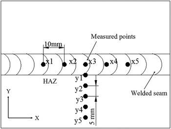
Five residual stress test points were used in the welded seam and heat affected zone (HAZ), and each point was measured for at least three times, and the average value was taken. As shown in the Fig. 2, in the welded seam, the distance between two adjacent points is 10 mm, which were labeled from x1 to x5. In contrast to the welded seam, the distance between two adjacent points in HAZ is 5 mm, which were labeled from y1 to y5.
Measured points of residual stress.

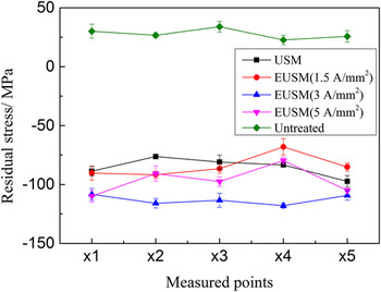
In the welded seam, the welding residual stress subjected to different treatments and different electropulse current densities are shown in Fig. 3. The as-welded specimen shows residual tensile stress that ranges from 22 to 34 MPa (28 MPa in average). After the surface modification (either USM or EUSM), as shown in Fig. 3, the original residual tensile stress is replaced by the residual compressive stress. This is beneficial to the mechanical properties of the joint. The maximum compressive residual stress subjected to USM is about −97 MPa, and the average value achieves −85 MPa, which indicates an eliminating rate of 400%. Compared to USM, even higher eliminating rates can be achieved in EUSM treated samples. Though at 1.5 A/mm2 the eliminating rate is comparable to the USM sample, when increasing the current density to 3 A/mm2 and 5 A/mm2, a noticeable increase in the eliminating rate is observed. For 3 A/mm2 the number goes to 500%, while for 5 A/mm2 an eliminating rate of 440% is shown.
Residual stress distribution in welded seam.

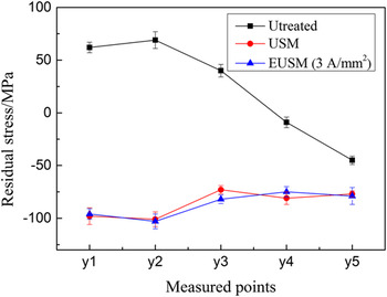
HAZ is essential to welded joint, since crack propagation usually happens here. When components are subjected to welding, the nonequilibrium process of rapid heating and cooling often results in residual tensile stress in the sample. This effect is found to be particularly obvious in the welded toe, where the materials undergo severe deformation and nonequilibrium heating. The residual stress distribution in HAZ is presented in Fig. 4. It can be seen that in the present study, residual stress arrives at 62 MPa in the region of welded toe. With increased distance between the measured points and weld toe, the value of residual stress decreases. After USM was used in the components, the tensile stress is eliminated and the stress state changes to compressive stress. Meanwhile, residual stress value seems to become less dependent on the position of the measured point. The average value is about −87 MPa. It is noted that after the application of EUSM, the residual stress distribution is similar to the USM processed samples. This should result from the very low current densities in the HAZ: since the electrodes are applied at both side of welded seam, very little current went through the HAZ.
Residual stress distribution in HAZ.

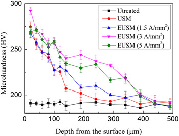
Figure 5 presents the microhardness distribution in the welded seam surface induced by USM and EUSM process. For the untreated samples, the microhardness is about 192 Vickers hardness (HV) at the top surface and keeps almost constant with the increasing distance from the surface. After USM processing, the microhardness achieves an effective improvement and reaches 275 HV at the surface. However, the microhardness begins to decrease sharply as the depth increases, and finally levels off at 150 μm, after which it exhibits approximately the same value as that of the untreated sample. Specimens subjected to EUSM processing with electropulse current density of 1.5 A/mm2 shows a similar phenomenon at the beginning. However, regarding the depth of the strengthened layers, it brings in a slight improvement from 150 μm to 300 μm. Increasing the electropulse current density to 3 A/mm2 leads significant improvement in both surface microhardness and the depth of strengthened layers. The former reaches 295 HV at the surface and the latter is increased to ∼450 μm. Moreover, the microhardness declines much more mildly as the depth increases. For instance, when the depth reaches 200 μm, it still shows a hardness value of 244 HV, where the USM almost lost its influence. When further increasing the electropulse current density to 5 A/mm2, the maximum microhardness decreases drastically and becomes almost the same as that of the USM processed material. However, it still shows significant strengthening effect inside the materials (although the effect is less obvious if compared to that of the 3 A/mm2 specimen).
Microhardness distribution in welded seam.

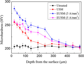
The microhardness distribution of base material subjected to USM and EUSM processing is given in Fig. 6. The microhardness maintains at about 205 HV uniformly before striking. Applying USM brings in strengthened surface layers, which shows a hardness of 256 HV at the surface. Then the microhardness begins to decrease sharply as the depth increases, leading to a very small depth of the strengthened layer. In contrast, for the specimen subjected to EUSM with a current density of 3 A/mm2, both the effective depth and surface microhardness are significantly improved. At the top surface, the hardness reaches 293 HV and the strengthening effect does not disappear until a depth of 300 μm. Further increasing the electropulse current density to 5 A/mm2, similar to the welded seam, the surface microhardness reduces sharply. The surface microhardness decreases to 260 HV, which is 33 HV less than that of 3 A/mm2 sample. However, it remains an effective reinforcement from the top surface to depth of ∼300 μm. This effect though is as good as that in the EUSM (3 A/mm2), is still much better than USM case. It can be seen that the EUSM with suitable parameter not only improves the surface maximum microhardness but also improves the depth of the strengthened layer. These may be attributed to the grain refinement and the increased dislocation density.
Microhardness distribution in base material.

B. Microstructure
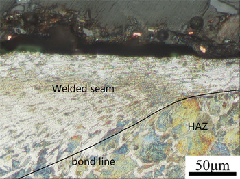
The microstructure in the welded toe treated by EUSM is illustrated in Fig. 7. The welded seam stands in the north-west zone. After EUSM processing, a refined microstructure with evidence for SPD layer can be observed on the surface. The microstructure is significantly deformed and leads to over 200 μm deformed layer. It is hard to identify the grain boundaries due to the repeatedly striking. The south-east part presents the HAZ microstructure. The HAZ underwent less plastic deformation because of its isolation from the top surface and the high deforming resistance of bulk pearlites. The bond line stands between the welded seam and HAZ. The bond line is densely fused due to the severely ultrasonic vibration and electropulsing.
Microstructure in welded toe.

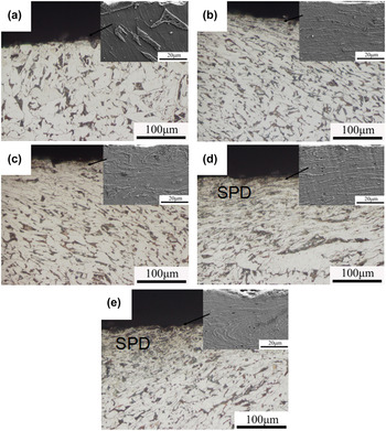
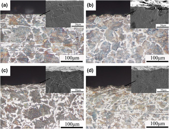
The microstructure in welded seam is shown in Fig. 8. Figure 8(a) presents the microstructure in the welded seam before treated. It shows a large amount of ferrite and small amount of pearlite located in the ferrite grain boundaries. Figure 8(b) shows the plastic deformation layer after USM treatment. A gradient microstructure layer with a depth of about 100 μm lies on the top of the surface. The grains are significantly deformed as shown in the SEM figure on the upper-right corner. The specimen suffered by EUSM processing with electropulse current density of 1.5 A/mm2 is given in Fig. 8(c). The microstructure is similar to the USM samples with a deformation layer of about 100 μm. Figure 8(d) characterizes the surface microstructure after EUSM treated with electropulse current density of 3 A/mm2. The degree of plastic deformation on the surface microstructure is severer than that of specimens treated with other parameters. A SPD layer is formed on the top surface with a depth of over 300 μm. The grains are elongated in the direction paralleled to the sample surface with ferrites and pearlites fragmented into strips as shown in the SEM figure. Figure 8(e) shows the surface microstructure after EUSM with electropulse current density of 5 A/mm2. The depth of SPD layer and the degree of plastic deformation are less than Fig. 8(d). Besides, some pits appear on the top surface indicate severe deformation. Since ultrasonic gun strikes heavily on the surface, the repeatedly striking leads to severer plastic compressive deformation than others. The EUSM processing with a suitable parameter has a significant improvement for welded seam microstructure.
Microstructure in welded seam (a) original specimen, (b) USM specimen, (c) EUSM specimen with 1.5 A/mm2, (d) EUSM specimen with 3 A/mm2, (e) EUSM specimen with 5 A/mm2.

The microstructure in base materials (S50C steel) before and after USM and EUSM processing is illustrated in Fig. 9. Figure 9(a) shows the microstructure of original base materials, which contains a large number of bulk pearlites and small amount of ferrites distributes along the pearlites grain boundaries. The specimen after USM treated is characterized in Fig. 9(b). Due to the high deformation resistance of bulk pearlites, the deformation zone at the surface is only ∼20 μm in depth. Moreover, some pits and cracks are observed on the top surface, which indicates the occurrence of severe deformation. Figure 9(c) shows the EUSM sample with electropulse current density of 3 A/mm2. It is apparent that the surface is smoother than that in Fig. 9(b). Additionally, the depth of the plastic deformation layer is almost doubled (∼40 μm) compared to Fig. 9(b). The SEM figure illustrates that the grains undergoes severe deformation, leading to grain refinement. Furthermore, the grains were elongated in the direction paralleled to the sample surface. The surface materials processed by EUSM with electropulse current density of 5 A/mm2 are presented in Fig. 9(d). It shows a gradient microstructure with a SPD layer of about 50 μm. The degree of plastic deformation in top surface is even severer than that of samples treated by other parameters. However, many pits are found on the top surface, which may undermine the mechanical properties, because the fatigue crack often propagates from these pits.
Microstructure in base materials (a) original specimen, (b) USM specimen, (c) EUSM specimen with 3 A/mm2, (d) EUSM specimen with 5 A/mm2.

IV. DISCUSSION
A. Effect of EUSM on microstructure and surface properties
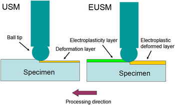
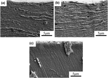
The significant improvement in the surface mechanical properties is strongly dependent on the strengthened microstructure. The microstructures of original materials are mainly composed of coarse grains. In EUSM, due to the formation of electroplasticity layers on the materials surface, the grains are severely deformed. The schematic diagrams of the USM and EUSM process are depicted in Fig. 10. High-frequency collision of shocking ball tip and the specimen surface brings in SPD layer. During the processing, the time interval between two shocks is so short that the elastic recovery is restricted. Thus, overlap of multi-elastic deformation leads to the plastic compressive deformation even if the stress value is less than the yield strength. However, for the hard-to-deform materials, such as S50C steel, ultrasonic striking has little influences on its strengthening. In this case, electropulsing is applied on the surface of materials to produce dynamic recrystallization softening to form electroplasticity layer and induce transient phase change, which is invariably accompanied by thermal and athermal effects. Reference Xu, Tang, Ding, Tian and Tian41–Reference Ye, Tse, Tang and Song44 The thermal effect is similar to high-rate heating called Joule heat, which heats the surface materials and generates a slightly high surface temperature related to the applied frequency. Reference Wang, Chen, Liu, Song and Tang45 At this temperature, mobility of dislocations, atomic diffusion and boundary mobility are enhanced, which leads to higher ductility. However, during the short processing time, the nondirection heat transfer and the limit heating energy cause thermal effect play an assistant role in the surface modification. Thanks to the electron wind force produced by athermal effect, it brings in more external energy than the traditional heat treatment, resulting in high mobility of dislocations and nucleation rate of the recrystallization during the process. In fact, nucleation is dependent on the dislocation motion through slip and climb, where the velocity of climb is considered as the decisive factor and is controlled by vacancy diffusion. Reference Zhu, To, Lee, Liu, Jiang and Tang46–Reference Zhu, Liu, Tang, Shi and Fu48 For the conventional methods, nucleation and phase change are depended on high temperature since it accelerates vacancy diffusion and dislocation climb. However, a very active climb of dislocations which plays a great role in nucleation can take place at relatively low temperature under electropulsing. That is to say, electropulsing can effectively accelerate the activity of vacancies and thus the climbing of dislocations. This leads to enhanced rate of nucleation for both phase transformation and recrystallization. Furthermore, electropulsing has another effect which is retarding the subsequent grain growth. Since a major driving force for the growth of newly recrystallized grains is the stored energy of the residual dislocation density. The lower dislocation density in the electropulsed samples provides a smaller driving force and thus a smaller growth rate. Reference Zhou, Xiao and Guo47 Thus, the welded components suffer from a fully recrystallization softening by thermal and athermal effects. In this case, the grains are refined, from which more pronounced grain-boundary compatibility are arose, leading to preferable ductility and deformation ability. What is more, the phase change induced by EPT may play a significant role in decreasing the extent of lattice distortion and supersaturated solid solution, leading to the relief of internal residual stress. Thus, ductility and deformation ability of welded components get noticeable improvement. Therefore, with the help of electropulsing, ultrasonic vibration energy can permeate deeper than traditional USM process and leads to further recrystallization and higher dislocation density as well as the formation of deeper SPD layers. The severe grain deformation and refinement lead to large lattice reconstruction in components, which is accompanied by the relaxation of residual strains. The stress state becomes more and more stable and hence gets great elimination. Thus, EUSM process would cause a dramatic enhancement in the surface plastic deformation, residual stress and surface behaviors due to the strengthened microstructure. The degree of deformation subjected to USM and EUSM is described in Fig. 11. Figure 11(c) shows the untreated sample, the grains stand regular with bulk ferrite and pearlite. Figure 11(a) presents the microstructure obtained by USM. On the top surface exists some deformation strips. Moreover, some bulk pearlites are deformed into strips and can be easily identified. For the EUSM processing specimen, as characterized in Fig. 11(b). There are more overlap deformations strips appearing on the top surface than the USM sample. Besides, the strips are thicker than those in the USM sample, which indicates severer plastic deformation and deeper deformation layer. Furthermore, the adjacent deformation strips are overlapped tightly, which makes it hard to distinguish the grain boundaries. Therefore, the EUSM has a significant improvement in surface plastic deformation and brings in better surface properties.
Schematic diagram of the USM and EUSM process.

Microstructure near the surface in welded seam (a) USM specimen, (b) EUSM specimen, (c) untreated specimen.

B. Effect of EUSM on surface plastic damages
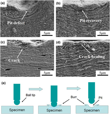
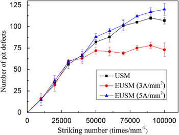
Surface mechanical properties are also strongly affected by surface morphology, including surface roughness and plastic damages. Figure 12 shows the formation of surface plastic damages by USM and EUSM process. Figures 12(a) and 12(b) illustrate the pits and their recovery on the materials surface. Because grain refinement is mainly determined by the large strain plastic deformation, material structure presents the gradient distribution in depth. The severe strikings result in deep strengthening layer and poor surface roughness. Furthermore, microcracks usually propagate from the pits as presented in Fig. 12(c). The microcracks would seriously restrict the performance, since fatigue damages usually begin here. The formation of plastic damages can be seen in Fig. 12(e). The materials surface is smooth before applying treatment. Then the ultrasonic ball tip strikes the materials surface heavily and forms pits on the surface. Normally, the pits can recover within a short time. However, ultrasonic generator outputs high-frequency vibration with over ten thousand times per second, the time interval between two shocks is so short that the elastic recovery is restricted and results in permanent pit defects on the surface. For difficulty-deformation materials, as shown in Figs. 12(c) and 12(d), they have poor ductility, so ultrasonic shock has little influence on their deformation. However, some parts of the microstructure have good ductility, such as grain boundaries. This nonequilibrium plastic deformation is inclined to form stress concentration in the pits. To build an equilibrium stress state, this stress concentration inevitably forces adjacent metals to deform. The adjacent metals are hard to deform due to their high deformation resistance. When the stress exceeds the yield strength, it normally leads to fractures. Thus, severe deformation is likely to bring in crack propagation around the pits. In this case, electropulsing is used in materials to improve the ductility and deformation ability as described above. Meanwhile, electropulsing has potentials to cause surface recovery and heal crack due to the Joule heat generated by the high density electric current and thermal compressive stress at the crack tips. Reference Lin, Zhao, Gao and Han25,Reference Hosoi, Nagahama and Ju27,Reference Qin and Su49 These can eliminate the microcracks to some extent as shown in Fig. 12(d). This phenomenon may be attributed to the soft surface caused by massive electropulsing energy, which leads to fully recrystallization softening and the crack-healing under high-energy EPT. Generally, crack is healed by high temperature and/or high pressure. When the electropulse current is applied across the crack, it would cause current detours between the crack tips because of the high electrical resistance on the crack surface. These detours would cause high electropulse current density and then dramatically increase the local temperature to melting point. Thanks to the high pressure generated by severe impacts, the crack would be healed by high temperature and pressure within a short time. While if the electropulse current is too high, it would cause large melting area around the specimen and softer metal layer, which is harmful for the materials processing. In this case, severe impact forces the ultrasonic ball tip to penetrate through the soft and melting metal layer, resulting in worse surface roughness and permanent destruction. The relationship between striking number and the number of pit defects is shown in the Fig. 13. When the striking number is lower than 30,000 times per mm2, EPT is ineffective for the pit recovery. Further increasing the striking number, the number of pits increases slowly under EUSM with electropulsing current of 3 A/mm2. For 5 A/mm2, however, a more rapid increase took place. This phenomenon is the same as the result above. Since EUSM with suitable parameter would improve the surface deformation ability, it would restrict the formation of pits. However, too high the current density would induce large melting and soften materials, which are harmful for further processing. Thus, the EUSM with higher current density notably increases the pits as shown in Figs. 8 and 9. The EUSM process consists of the enhancement of surface strength layer and the formation of surface plastic damages. Therefore, this coupling process with suitable parameter has a significant improvement on surface morphology.
Surface morphology by USM and EUSM (a) and (c) are corresponding to USM and (b) and (d) are corresponding to EUSM, (e) formation of plastic damages.

The relationship between striking number and the number of pit defects.

V. CONCLUSIONS
In the present study, EUSM process is carried out for S50C steel welded components. The results show that surface properties and microstructure achieve significant improvements by EUSM process, leading to deeper strengthened layers with gradient microstructure on the surface and higher levels of surface compressive residual stress than conventional USM process. In addition, surface microhardness and its effective depth are enhanced by EUSM with appropriate electropulsing parameters. At 3 A/mm2, the hardness of the top surface is increased to 295 HV while the depth of the strengthened layer reaches 400 μm. Conventional USM process is inevitably accompanied by some plastic damages, such as pits and microcracks. The damages, however, can be eliminated by EUSM. These enhancements may be attributed to the thermal and athermal effects caused by EPT, which can increase the nucleation rate and retard the subsequent rate of grain growth. Thus, welded components are softened by dynamic recrystallization, leading to good ductility and deformation ability. Hence, the ultrasonic vibration energy can permeate deeper than conventional USM process. Therefore, EUSM is a highly efficient and energy-saving external field assisted processing technique to prepare outstanding surface properties of welded components.
ACKNOWLEDGMENTS
This work is supported by Shenzhen Development & Reform Commission Funding Project (No. SFG2015-1033), Shenzhen Special Funding Project for Development (No. JCYJ20140417115840280), and Key Enterprises & Innovation Institutes Supporting Funding Project of Nanshan District of Shenzhen City (No. KC2015ZDYF0021A).