




1 Introduction
Unlike horizontal-axis wind turbines (HAWTs), rotors of vertical-axis wind turbines (VAWTs) can take different aspect ratios. The frontal area of HAWT rotors has a circular shape, and thus, the ratio of the vertical and spanwise extents of HAWT rotors (i.e. the aspect ratio) is by definition always equal to 1. VAWT rotors, on the other hand, can theoretically take any aspect ratio; they can have long blades and a small rotor diameter or, conversely, short blades and a large rotor diameter. Therefore, rotor aspect ratio is one of the intrinsic features of VAWTs which clearly differentiates them from HAWTs. In this study, we focus on this intrinsic feature of VAWTs and, in particular, investigate its effect on VAWT wakes.
Despite the significant existing body of knowledge on flows through VAWTs (for example, see the following. Reviews: Paraschivoiu (Reference Paraschivoiu2002) and Porté-Agel, Bastankhah & Shamsoddin (Reference Porté-Agel, Bastankhah and Shamsoddin2020). Experiments: Brochier et al. (Reference Brochier, Fraunie, Beguier and Paraschivoiu1986), Tescione et al. (Reference Tescione, Ragni, He, Simão Ferreira and van Bussel2014), Araya & Dabiri (Reference Araya and Dabiri2015), Bachant & Wosnik (Reference Bachant and Wosnik2015), Edwards, Danao & Howell (Reference Edwards, Danao and Howell2015), Ryan et al. (Reference Ryan, Coletti, Elkins, Dabiri and Eaton2016), Parker, Araya & Leftwich (Reference Parker, Araya and Leftwich2017) and Rolin & Porté-Agel (Reference Rolin and Porté-Agel2018). Large-eddy simulation (LES): Shamsoddin & Porté-Agel (Reference Shamsoddin and Porté-Agel2014, Reference Shamsoddin and Porté-Agel2016), Hezaveh et al. (Reference Hezaveh, Bou-Zeid, Lohry and Martinelli2017) and Abkar & Dabiri (Reference Abkar and Dabiri2017). Both LES and experiments: Posa et al. (Reference Posa, Parker, Leftwich and Balaras2016)), conclusive studies on the effect of aspect ratio on VAWT wakes cannot be found in the literature. Nevertheless, it is worth mentioning that Brusca, Lanzafame & Messina (Reference Brusca, Lanzafame and Messina2014) investigated the effect of rotor aspect ratio on the power performance of VAWTs.
Turbine dimensions.

That being said, a look into the literature on bluff-body wakes reveals interesting works on the effect of the shape of wake-generating objects on the wake flow behind them. We mention, therefore, some of these studies in the following. Bevilaqua & Lykoudis (Reference Bevilaqua and Lykoudis1978) carried out experiments to compare the self-preserving nature of the wakes of a sphere and a porous disk with the same drag. They showed that, although in both cases the wake reached a self-preserving state, there are differences in the turbulence structure of the wake even after reaching that state, mainly because of the presence (for the sphere) and absence (for the porous disk) of vortex shedding, due to the geometry of the wake-generating object. Meunier & Spedding (Reference Meunier and Spedding2004) performed measurements of the wakes generated by six different bluff bodies (five axisymmetric objects and a cube) in stratified flow. As different objects have different drag coefficients, they showed that, by normalizing the lengths by an effective diameter (which is a function of the drag coefficient and diameter of the object), they could reach a common behaviour in the wake mean velocity field. Sumner, Heseltine & Dansereau (Reference Sumner, Heseltine and Dansereau2004) experimentally studied the wake of a finite cylinder, which was mounted normal to a ground surface, with different aspect ratios. In their study, they focused more on the vortex structure of the wake, and found similar wake structure and power spectra for most of the aspect ratios that were analysed.
Schematic of the numerical experiments. Three turbines are shown in black (T1), green (T2) and red (T3).

Inflow characteristics: (a) vertical profile of the mean streamwise velocity compared to a log-law profile (horizontal axis in logarithmic scale). (b) Vertical profile of the mean streamwise velocity (linear scale). (c) Vertical profile of the standard deviation of the streamwise velocity.

Considering that there is still much room for conclusive research on the specific effect of aspect ratio on the mean flow structure of a wake of an object (for example, cylinders and, especially, VAWTs), we are interested in performing such a study in this paper, with the particular aim of investigating if a common wake behaviour can be elicited from the wake of VAWTs of different aspect ratio. We believe that this study is useful from both a pure fluid mechanics point of view and an applied wind engineering one.
This article is structured in the following fashion. In § 2, the objective of the study is laid out. In § 3, the numerical experiments, which are performed for three VAWTs of different aspect ratio, are described and some first results are shown. In § 4, we try to find a common behaviour in those wakes. Finally, § 5 concludes the paper.
Contours of the normalized mean streamwise velocity ( $\overline{u}/U_{eq}$) in the
 $x{-}y$ plane at the equator height of the turbine for (a) T1, (b) T2 and (c) T3.

Contours of the normalized mean streamwise velocity ( $\overline{u}/U_{eq}$) in the
 $x{-}z$ plane going through the centre of the turbine for (a) T1, (b) T2 and (c) T3.

2 Objective of the study
The main objective of this paper is to investigate the answer to this question: What happens to the wake of a VAWT when we change the aspect ratio of the turbine? By aspect ratio, we mean the ratio of the rotor height to its diameter. In our investigation, we are particularly interested in finding out whether there is a similarity or a universal pattern that can explain the behaviour of the wake generated by objects of varying aspect ratio.
In order to achieve this objective, we first perform a set of numerical experiments, which are designed in a systematic fashion useful for reaching our goal. With the results of these experiments, we first highlight the ‘differences’ in the wakes originating from turbines of different aspect ratio. Subsequently, in the second step of our study, we try to seek ‘similarities’ in those wakes.
Horizontal-spanwise profiles of the normalized mean streamwise velocity deficit ( $\overline{u}_{d}/U_{eq}$) in the
 $x{-}y$ plane at the equator height of the turbine at different downstream positions for T1 (black), T2 (green) and T3 (red). All lengths are normalized by
 $D$. The blue horizontal dashed lines show the extent of the turbine.

Vertical profiles of the normalized mean streamwise velocity deficit ( $\overline{u}_{d}/U_{eq}$) in the
 $x{-}z$ plane going through the centre of the turbine at different downstream positions for T1 (black), T2 (green) and T3 (red). All lengths are normalized by
 $D$. (
 $z_{t}=z-z_{eq}$, where
 $z_{eq}$ is the equator height of the turbine.)

3 Numerical experiments
3.1 Set-up of the experiments
The numerical experiments are carried out using an LES framework. The set-up of the simulations is shown in figure 1. As can be seen in the figure, we have considered three straight-bladed VAWTs with three different aspect ratios  $\unicode[STIX]{x1D709}=H/D$. The turbines have the same rotor diameter
 $D$ and different rotor heights
 $H$. Table 1 gives a summary of the three turbines’ dimensions. Although turbine T3’s dimensions are most likely unrealistic, we have intentionally chosen these dimensions, in order to have an extreme case which together with the other cases offers a wide spectrum of aspect ratios; this makes our study wide-ranging and more comprehensive. Also note that the turbines are placed such that the equator height of their rotor is the same for all three cases. Furthermore, all three turbines have the same tip-speed ratio (4.5) and the same thrust coefficient (0.8), just as was the case in Shamsoddin & Porté-Agel (Reference Shamsoddin and Porté-Agel2016).
The same as figure 5, except that now the streamwise distance is normalized by  $D_{eq}$.

The same as figure 6, except that now the streamwise distance is normalized by  $D_{eq}$.

The same as figure 5, except that now all distances are normalized by  $D_{eq}$.

The same as figure 6, except that now all distances are normalized by  $D_{eq}$.

To perform the simulations, we use the LES framework (with an actuator line model to parameterize the turbines) that is already used and validated for VAWT wake simulations in Shamsoddin & Porté-Agel (Reference Shamsoddin and Porté-Agel2014, Reference Shamsoddin and Porté-Agel2016). Moreover, this framework has been validated in other similar wake simulation studies (for example, Porté-Agel et al. Reference Porté-Agel, Wu, Lu and Conzemius2011; Wu & Porté-Agel Reference Wu and Porté-Agel2011; Shamsoddin & Porté-Agel Reference Shamsoddin and Porté-Agel2017). The code has been shown to yield grid-independent results, provided that a minimum number of grid points is used to resolve the rotor (Shamsoddin & Porté-Agel Reference Shamsoddin and Porté-Agel2014). In this study, we chose a resolution (15 points in each horizontal direction covering the rotor area) that falls within the grid-independent range. The dimensions of the computational domain and the position of the buffer zone (used to feed the inflow to the domain) are shown in figure 1. The number of grid points in the streamwise ( $x$), spanwise (
 $y$) and vertical (
 $z$) directions is
 $N_{x}=360$,
 $N_{y}=180$ and
 $N_{z}=240$, respectively. For the sake of conciseness, we refer the interested reader to the above-mentioned references (Shamsoddin & Porté-Agel Reference Shamsoddin and Porté-Agel2014, Reference Shamsoddin and Porté-Agel2016) to obtain more details about the LES framework and the manner in which the inflow is fed to our simulations. The inflow characteristics are shown in figure 2.
3.2 LES results: focus on differences
After simulating the flow past the three turbines, we can take a look at the mean flow field for each case. Figures 3 and 4 show contour plots of the mean flow velocity for each case: in the horizontal plane at the equator height of the turbine and in the vertical plane through the centre of the turbine, respectively. Moreover, figures 5 and 6 show the vertical and horizontal profiles of the velocity defect (defined as  $\overline{u}_{d}=\overline{u}-U_{o}$, where
 $U_{o}$ is the inflow velocity profile). In all the figures in this paper, the velocities are normalized by
 $U_{eq}$, which is the mean inflow streamwise velocity at the equator height of the turbine (i.e.
 $z=2D=100~\text{m}$ in all cases). It is worth mentioning here that, as can be seen in the profiles of figure 5, the lateral asymmetry of the wake is very small, and practically negligible, due to the relatively high tip-speed ratio of the turbine (4.5).
The significant difference in the wake strength, size and recovery is clearly visible in these four figures. These differences are compatible with common sense intuition considering the substantial differences in the height (or aspect ratio) of the three turbines. Of particular interest is the clear variation in the width of the wake in the  $y$ direction (figures 3 and 5), although the width of the turbine in the
 $y$ direction (i.e. the rotor diameter) is the same for the three cases. The general trend is simple: as the turbine height
 $H$ increases, the wake becomes longer (in the
 $x$ direction), taller (in the
 $z$ direction) and wider (in the
 $y$ direction).
4 Seeking similarity
In this section, our purpose is to identify a universal behaviour in the mean velocity field of the wake flow behind VAWTs of different aspect ratio. In order to do so, we first have a look into the concept of momentum thickness (or more precisely ‘momentum diameter’ for our case), which will eventually prove to be useful for our study (similar to what Meunier & Spedding (Reference Meunier and Spedding2004) have done). To start, we write the well-known momentum integral for a turbulent three-dimensional wake (Tennekes & Lumley Reference Tennekes and Lumley1972):
 $$\begin{eqnarray}T=\unicode[STIX]{x1D70C}\int _{A_{yz}}\overline{u}(U_{o}-\overline{u})\,\text{d}A,\end{eqnarray}$$
where  $T$ is magnitude of the total thrust (or drag) force exerted by the wake-generating object on the flow,
 $\unicode[STIX]{x1D70C}$ is the fluid density and
 $A_{yz}$ is any
 $yz$-plane, over which the integral is computed. Similar to the definition of the momentum thickness for planar wakes (
 $\unicode[STIX]{x1D70C}U_{o}^{2}\unicode[STIX]{x1D703}=M$, where
 $\unicode[STIX]{x1D703}$ is the momentum thickness and
 $M$ is the total drag force per unit depth) (Tennekes & Lumley Reference Tennekes and Lumley1972), we can define a length scale, called ‘momentum diameter’:
 $$\begin{eqnarray}\unicode[STIX]{x1D70C}U_{o}^{2}{\displaystyle \frac{\unicode[STIX]{x03C0}}{4}}\unicode[STIX]{x1D6FF}^{2}=T,\end{eqnarray}$$
where  $\unicode[STIX]{x1D6FF}$ is the momentum diameter. Now, considering the definition of the thrust coefficient (i.e.
 $T=(1/2)\unicode[STIX]{x1D70C}A_{f}U_{o}^{2}C_{T}$, where
 $A_{f}$ is the frontal area of the wake-generating object and
 $C_{T}$ is the thrust coefficient), we can obtain the following equation:
 $$\begin{eqnarray}T=\unicode[STIX]{x1D70C}U_{o}^{2}{\displaystyle \frac{\unicode[STIX]{x03C0}}{4}}\unicode[STIX]{x1D6FF}^{2}={\displaystyle \frac{1}{2}}\unicode[STIX]{x1D70C}A_{f}U_{o}^{2}C_{T}.\end{eqnarray}$$
After rearranging, we obtain
 $$\begin{eqnarray}\unicode[STIX]{x1D6FF}=\sqrt{{\displaystyle \frac{1}{2}}C_{T}}\sqrt{{\displaystyle \frac{4}{\unicode[STIX]{x03C0}}}A_{f}}.\end{eqnarray}$$
Defining the equivalent diameter  $D_{eq}\equiv \sqrt{(4/\unicode[STIX]{x03C0})A_{f}}$, the above equation can be written as
 $$\begin{eqnarray}\unicode[STIX]{x1D6FF}=D_{eq}\sqrt{{\textstyle \frac{1}{2}}C_{T}}.\end{eqnarray}$$
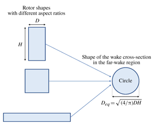
Note that  $D_{eq}$ is the diameter of an equivalent circular disk that has the same frontal area as that of the wake-generating object (in our case, the VAWT). The momentum diameter expression (4.5) is obtained without any specific assumption about the geometry of the wake-generating object. As can be seen, this length scale is only a function of the thrust (drag) coefficient and the frontal area of the object.
Now, turning back to our problem of VAWTs with different aspect ratios, we notice that  $A_{f}=DH$ and
 $D_{eq}=\sqrt{(4/\unicode[STIX]{x03C0})DH}$. Moreover, as the thrust coefficients of the three turbines are the same (see § 3.1), we hypothesize that
 $D_{eq}$ can serve as a relevant normalizing length scale, which can be useful in eliciting a universal wake behaviour for VAWTs of different aspect ratio. To test our hypothesis, we first investigate the wake profiles of the three turbines when normalized by
 $D_{eq}$ in the streamwise (
 $x$) direction in figures 7 and 8. We see that the maximum deficit points for all three turbines now collapse onto each other at the same normalized streamwise positions. However, the wake width still shows different values.
Finally, if we normalize the distances both in streamwise and lateral ( $y$ and
 $z$) directions with
 $D_{eq}$, we obtain profiles of figures 9 and 10. In these figures, we see a remarkable collapse of the mean velocity deficit profiles onto each other in the far wake.
5 Conclusion
In this paper, we aimed at studying the effect of aspect ratio on the wakes of VAWTs. We performed numerical experiments for three VAWTs with different rotor aspect ratios (2, 1 and  ${\textstyle \frac{1}{4}}$) but with the same thrust coefficient (
 $C_{T}=0.8$). The numerical experiments were carried out using an already validated LES framework. The wakes of these three turbines showed, as expected, significant differences in their mean flow field. However, in an attempt to elicit a universal behaviour in these wakes, we took advantage of the concept of ‘momentum diameter’ and defined an equivalent diameter
 $D_{eq}=\sqrt{(4/\unicode[STIX]{x03C0})DH}$ for a VAWT rotor. We observed that if we normalize the lengths in all three directions with
 $D_{eq}$, the mean velocity profiles of the three VAWT wakes collapse remarkably well onto each other. As a consequence, we observe that the cross-section of the wakes generated by turbines of different aspect ratio eventually converges to a circular shape (i.e. the lateral aspect ratio of the wake’s cross-section converges to 1), even though in the near-wake region the wake cross-section tends to retain the relative aspect ratio of the turbine rotor. This is in contrast with the potential presumption – that one might intuitively make – that the wake retains an elliptic shape throughout the far-wake region (which is assumed by some models in the literature).
We believe this is a substantial result, which could help both in optimizing the design of VAWT rotors and also in optimization of the placement configuration of VAWT farms. Furthermore, these results could be of interest in the general fluid mechanics of bluff body wakes.
Acknowledgements
This research was supported by the Swiss National Science Foundation (grant 200021_172538) and the Swiss Federal Office of Energy. In addition, this project was carried out within the frame of the Swiss Centre for Competence in Energy Research on the Future Swiss Electrical Infrastructure (SCCER-FURIES) with the financial support of the Swiss Innovation Agency (Innosuisse – SCCER programme) (contract no. 1155002544). Computing resources were provided by the Swiss National Supercomputing Centre (CSCS) under Project ID s706.
Declaration of interests
The authors report no conflict of interest.



