Introduction
Lithium ion batteries (LIBs) are widely used for the power supply of the various portable devices because of their high-energy density. Because their anode potential is below the reduction voltage of aqueous solutions, organic solvents are used as the electrolyte. One origin of the ignition of current LIBs is the flammable nature of the organic liquid electrolytes. Non-flammable solid electrolytes are the key materials for the all-solid-state batteries compatible with the safety and high-energy density of LIBs. For example, high-capacity cathodes such as sulfur can be used in all-solid-state cells without dissolution of the discharge products (lithium poly-sulfides).[Reference Machida, Kobayashi, Nishikawa and Shigematsu1] For the high-power density of all-solid-state LIBs, high Li+ conductive solid electrolytes with low grain boundary resistances are highly required.
The types of ionic conduction in the solid electrolytes are divided into two cases. One is the conduction of the host ions in a given material. Based on the host ion conduction, Li compounds are the material candidates for the fabrication of Li+ ion conductors. The sulfides are the most promising materials for the practical application because of their exceptionally high Li+ ion conductivity. The Li+ ion conductivity of 10−2 S/cm at room temperature was firstly reported for Li10GeP2S12 (LGPS) in 2010.[Reference Kamaya, Homma, Yamakawa, Hirayama, Kanno, Yonemura, Kamiyama, Kato, Hama, Kawamoto and Mitsui2] The conductivity was further enhanced by the replacement of Ge4+ with Si4+ and partial substitution of S2− with Cl−.[Reference Kato, Hori, Saito, Suzuki, Hirayama, Mitsui, Yonemura, Iba and Kanno3] In general, the interface between the electrode active materials and the solid electrolytes must contact intimately for the facile charge transfer reaction. Regardless of the high Li+ ion conductivity in a bulk region, oxide materials are not always suitable for all-solid-state batteries due to the high grain boundary resistance.[Reference Anantharamulu, Koteswara Rao, Rambabu, Vijaya Kumar, Radha and Vithal4, Reference Stramare, Thangadurai and Weppner5] The poor contact with the active materials is the bottleneck for the construction of electrochemically favorable interface.[Reference Kobayashi, Takeuchi, Tabuchi, Ado and Kageyama6]
In general, the conventional high Li+ ion conductive solid electrolytes are facing on the convertibility with other properties required for the solid electrolyte. For example, LGPS-related compounds are quite high Li+ ion conductor, while the lack of the stability with Li metal is the bottleneck for the construction of the high-voltage LIB.[Reference Kato, Hori, Saito, Suzuki, Hirayama, Mitsui, Yonemura, Iba and Kanno3] Although garnet-type Li+ ion conductors are stable against Li metal, high-temperature sintering is necessary for the densification of the pellet, which will be a severe drawback for constructing an intimate contact with cathode materials.[Reference Thangadurai, Narayanan and Pinzaru7] A specific composition of Li2S-P2S5 glass with a minimum H2S release is not always high Li+ ion conductor.[Reference Muramatsu, Hayashi, Ohtomo, Hama and Tatsumisago8] The trade-off between the Li+ ion conductivity and other properties can be considered as the most fundamental problem for the conventional host Li+ conductors.
As mentioned above, most of the solid electrolytes have been developed based on the host ion conduction. On the other hand, guest ions can also migrate in a host lattice. For example, doped Cu+ ions diffuse in KCl.[Reference Hanson9] These ion conduction mechanism, where lightly doped guest ions play a major role for the total ion conduction, is called as “co-ionic conduction” or “parasitic conduction”.[Reference Lazzari and Scrosati10, Reference Miyazaki, Maekawa and Takamura11] Focusing on the guest ion conduction, new types of Li+ ion conductors can be fabricated based on Li-free compounds. For example, NaI has been reported to become a Li+ ion conductor via forming a solid solution with 6 mol% of LiBH4.[Reference Miyazaki, Kurihara and Hihara12–Reference Miyazaki, Sakaguchi, Weitzel and Hihara14] The guest Li+ ion conduction has been also confirmed for KI–KBH4–LiI system.[Reference Miyazaki and Hihara15]
One of the significant advantages of the material development based on Li-free compounds would be the wider materials selectivity. If the guest Li+ ions dominantly migrate in the arbitrary Li-free compounds, various kinds of materials will have a potential to become novel solid electrolytes. More specifically, if Li+ ions are intentionally doped to a given Li-free compound with desirable properties for battery applications (i.e., high electrochemical stability and excellent sinterability, etc.), this guest Li+ ion conductor will be more suited for the practical application compared with the conventional solid electrolytes with the trade-off mentioned above. Moreover, for some cases, guest Li+ ions migrate faster than the host Li+ ions in Li compounds.[Reference Miyazaki, Kurihara and Hihara12] Therefore, it can be expected that the guest Li+ conductors are compatible with high Li+ ion conductivity and other properties necessary for the battery application.
However, at the present stage, the reports of the Li+ ion conduction in Li-free alkali halides are restricted to two iodide compounds, NaI and KI.[Reference Miyazaki, Kurihara and Hihara12, Reference Miyazaki and Hihara15] The Li+ conduction properties in sodium bromide are still unclear. The purpose of this work is the demonstration of the guest Li+ ion conduction in NaBr. NaBr–LiBH4 system is fabricated and their Li+ ion conduction properties are investigated. The major ion conduction carrier will be determined by the electrochemical methods and time-of-flight secondary ion mass spectrometry (TOF-SIMS) measurement.
Experimental
All of the sample and cell fabrication processes were carried out in an argon-filled grove box. The oxygen concentration was kept at several ppm with the dew point of approximately −70 °C. NaBr (>99.9% purity), NaBH4 (>99.9% purity) and LiBH4 (>90% purity) were purchased from Aldrich Co. The sample fabrication methods were the same with those described in the previous reports.[Reference Miyazaki, Sakaguchi, Weitzel and Hihara14] The crystal structure of the samples were investigated by XRD measurement with paralleled beam of Cu Kα radiation at 45 kV and 200 mA using SmartLab (Rigaku Co., Japan). In order to avoid an air exposure during the measurement, powder sample was sealed by Kapton® films after mounting on the glass substrate. For the electrochemical measurement, powder sample was uniaxially pressed under 750 MPa, resulting in the dense pellet of 10 mm in diameter with a thickness of approximately 1 mm. Stainless steel (S.S.) electrodes were fixed on both the sides of the pellet. The three-layer cell was sealed in air tight cell (HS cell, Hohsen Corp.). The electrical conductivity was measured by AC impedance method using Solartron 1260 impedance analyzer from the frequency range between 1 Hz and 1 MHz. The measurement temperature was controlled in an oil bath and the conductivities were measured from 303 to 423 K at the intervals of 10 K. The fracture surface of the pellet was observed by SEM (S-4700, Hitachi High-Technologies Co.) before and after the conductivity measurement. Cyclic voltammetry (CV) was performed for the cell Li|15NaBr•LiBH4|Mo using PS08 (Toho Technical Research). The potential range was between −0.5 and 5.0 V (versus Li+/Li) at the sweep rate of 0.1 mV/s. The potentiostatic reduction at −0.5 V (versus Li+/Li) was also performed for the same cell construction and subsequently Mo foil was detached in a glove box. For the identification of the reduction product, the surface of Mo foil after DC potentiostatic measurement was analyzed by static TOF-SIMS (PHI TRIFT V nanoTOF™, ULVAC-PHI). The primary ion of TOF-SIMS was Bi3++ with an accelerating voltage of 30 kV. To avoid the hydration and oxidation of the deposited compounds, the Mo film was sealed in air tight holder and set to the sample chamber without air exposure.
Results and discussions
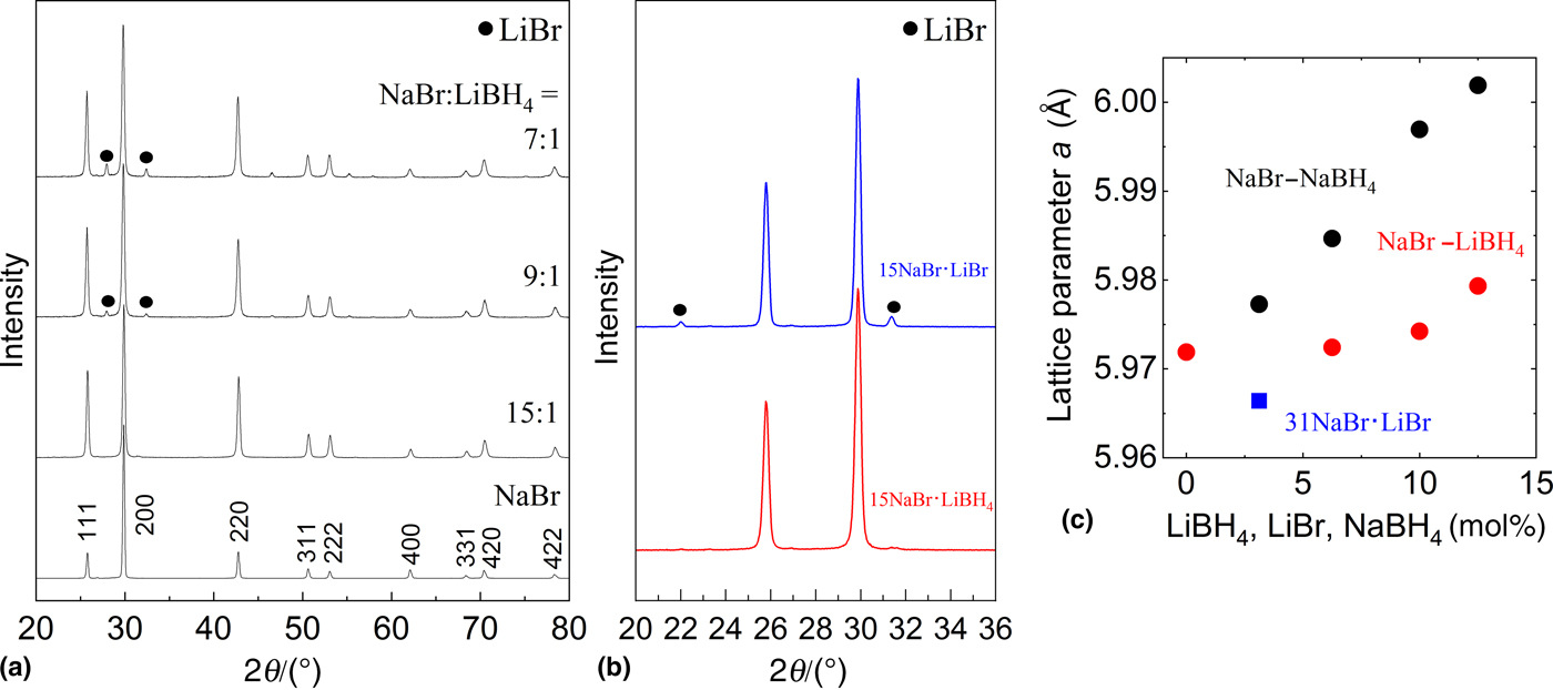
Figure 1(a) shows the results of XRD measurement for NaBr–LiBH4 system. The results for the samples ball-milled with 3, 6, and 10 mol% of LiBH4 were presented. The diffraction peaks of NaBr were mainly observed for 15NaBr•LiBH4, indicating the formation of solid solution between NaBr and LiBH4. However, as shown in black circle symbols in the figure, LiBr was confirmed to co-exist as the secondary phase when the mixed amount of LiBH4 exceeds 10 mol%. The presence of LiBr indicates that the anion exchange reaction occurs between NaBr and LiBH4, which has been also reported for the mixture of other metal borohydrides and halide compounds.[Reference Liu, Yang, Ni and Drews16, Reference Kumar, Kojima and Kumar17] The single phase of 9NaBr•LiBH4 (10 mol% LiBH4) has not been obtained at the present stage. The addition of LiBH4 into NaBr beyond the solubility limits results in the anion exchange reaction between Br− and BH4− ions. XRD patterns for 15NaBr·LiBr (blue) and 15NaBr·LiBH4 (red) in a low-angle region are presented in Fig. 1(b). LiBr is segregated as the secondary phase for 15NaBr·LiBr. Although the diffraction peaks of LiBr are not clearly observed for 15NaBr·LiBH4, at the present stage, we cannot conclude that 15NaBr·LiBH4 was obtained in a single phase. However, the segregation of LiBr is clearly suppressed by the co-existence of BH4− ions, which can be considered as the stabilization of the guest Li+ ions in NaBr lattice. A similar stabilization effect has been also reported for NaI–LiBH4 and KI–KBH4–LiI systems.[Reference Miyazaki, Kurihara, Hayashi, Furughori, Shomura and Hihara13, Reference Miyazaki, Noda, Miyazaki, Soda and Hihara18] Figure 1(c) shows the compositional dependence of the lattice parameters for NaBr–LiBH4, NaBr–NaBH4 (Li+-free) and NaBr–LiBr (BH4−-free) systems. The decrease of a axis value was confirmed for 31NaBr·LiBr, indicating the substitution of the host Na+ ions with the guest Li+ ions in NaBr lattice. On the other hand, the lattice size of NaBr was not largely changed by LiBH4 addition. Because of the following reasons, it can be said that the compositional variations of the lattice parameters are difficult to be detected in NaBr–LiBH4 system. In the six coordinated environment, the ionic size of the host Na+ ion (1.02 Å) is larger than that of the guest Li+ ion (0.76 Å).[Reference Shannon19] According to the past results on the XRD measurement of LiBH4–LiBr system, the Br− substitution in LiBH4 yields to the lattice shrinkage, indicating the smaller ion size of Br− than that of BH4−.[Reference Miyazaki, Kumatani, Kanno, Ando, Matsuo, Takamura, Orimo and Maekawa20] Therefore, the introduction of both Li+ and BH4− ions into NaBr would result in a smaller variation of the lattice size. In order to clarify the Li+ doping effect on NaBr–LiBH4 system, NaBr–NaBH4 system (Li+-free) was fabricated and their lattice parameters were compared with those of NaBr–LiBH4 system [black symbols in Fig. 1(c)]. The XRD patterns of NaBr–NaBH4 system are presented in Fig. S1 in Supplementary material. Because Li+ ions are not included, the variations of the lattice sizes of NaBr–NaBH4 system represent the effect of the substitution of Br− with BH4− ions. NaBr lattice monotonously expands via BH4− substitution. Within the solubility limit of LiBH4, the difference in the lattice sizes of NaBr–LiBH4 and NaBr–NaBH4 systems with the same anion ratio can be explained by the introduction of Li+ ions in NaBr. The lattice sizes were rather increased for 9NaBr·LiBH4 (10 mol%) and 7NaBr·LiBH4 (13 mol%). For these two samples, it was clearly confirmed that LiBr presents as the product of the anion exchange reaction between NaBr and LiBH4 [see Fig. 1(a)]. NaBH4 would also exist as another by-product during ball-milling and subsequently form a solid solution with NaBr in paralleled with the formation of NaBr–LiBH4 system. Rather expanded lattice size of NaBr–LiBH4 system beyond the solubility limit is perhaps due to the excess inclusion of NaBH4.
(a) XRD patterns for NaBr–LiBH4 system. Diffraction indices derived from NaBr are presented. (b) XRD patterns of 15NaBr·LiBr and 15NaBr·LiBH4 at lower angle region. Diffraction peaks of LiBr are presented as black symbols. (c) Compositional dependence of lattice parameters for NaBr–LiBH4 and NaBr–NaBH4 systems. The result for 31NaBr·LiBr (Li+:3 mol%) is plotted by blue symbol.

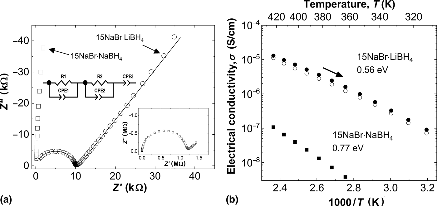
Electrical conductivity of 15NaBr·LiBH4 was measured and the results were presented in Fig. 2. Nyquist plots of the S.S. symmetric cells using 15NaBr·LiBH4 and 15NaBr·NaBH4 as the solid electrolytes are presented in Fig. 2(a). The data were obtained at 423 K. Equivalent circuit used for fitting the data is shown in the inset. Although the semicircle with the capacitance value of 10−11 F was mainly observed, extra RC component was simulated. The capacitance value of the semicircle at the low-frequency side was estimated to be the order of 10−5 F, indicating the contribution from the electrode polarization rather than the grain boundary resistance.[Reference Miyazaki, Sakaguchi, Weitzel and Hihara14] The resistance of the 15NaBr·LiBH4 was two orders of magnitude smaller than that of 15NaBr·NaBH4. The temperature dependence of the ionic conductivity of 15NaBr·LiBH4 and 15NaBr·NaBH4 is presented in Fig. 2(b) in a form of Arrhenius plot. The conductivities of the Li+-doped sample was larger than those of the Li-free one in a whole measured temperature range. As shown in an SEM image in Fig. S2, the fracture surface of the pellet after the conductivity measurement was dense and the pore was not clearly confirmed. This dense morphology of the pellet supports a small contribution from the inter-grain resistance as presented in Fig. 2(a). The conductivities of 15NaBr•LiBH4 after hot-pressing under 750 MPa and 423 K were presented by filled black symbols. Although the conductivities are rather enhanced by hot-pressing, the differences are small. These results indicate that sufficiently dense pellet can be obtained only by cold-pressing and sintering or hot-pressing is not needed for the densification of NaBr–LiBH4 pellet. From the slope of the Arrhenius plot, the activation energies of the ion conduction in 15NaBr•LiBH4 and 15NaBr•NaBH4 were estimated as 0.56 and 0.77 eV, respectively. The difference of the mobility may indicate that the conduction carriers in NaBr are changed by Li+ doping. The conductivities of 15NaBr·LiBH4 are lower than those of 15NaI·LiBH4.[Reference Miyazaki, Kurihara and Hihara12] Although the knee temperature corresponding to the extrinsic–intrinsic transition is not observed in the measured temperature range, the difference reflects the different mobility of the guest Li+ ions in NaBr and NaI lattices. Perhaps the smaller lattice size of NaBr and/or the smaller polarizability of Br− compared with that of I− can be the possible origin of rather high activation energy for the guest Li+ ion conduction in NaBr.
(a) Nyquist plots of 15NaBr·LiBH4 and 15NaBr·NaBH4 (“Li-free” sample). The stainless steels (S.S.) were used as the both side electrodes. The results for S.S.|15NaBr·NaBH4|S.S. is presented in lower right of the figure. (b) Temperature dependence of the conductivity for 15NaBr·LiBH4 (open circles) and 15NaBr·NaBH4 (filled squares). The results for the hot-pressed 15NaBr·LiBH4 are presented by filled circle symbols.

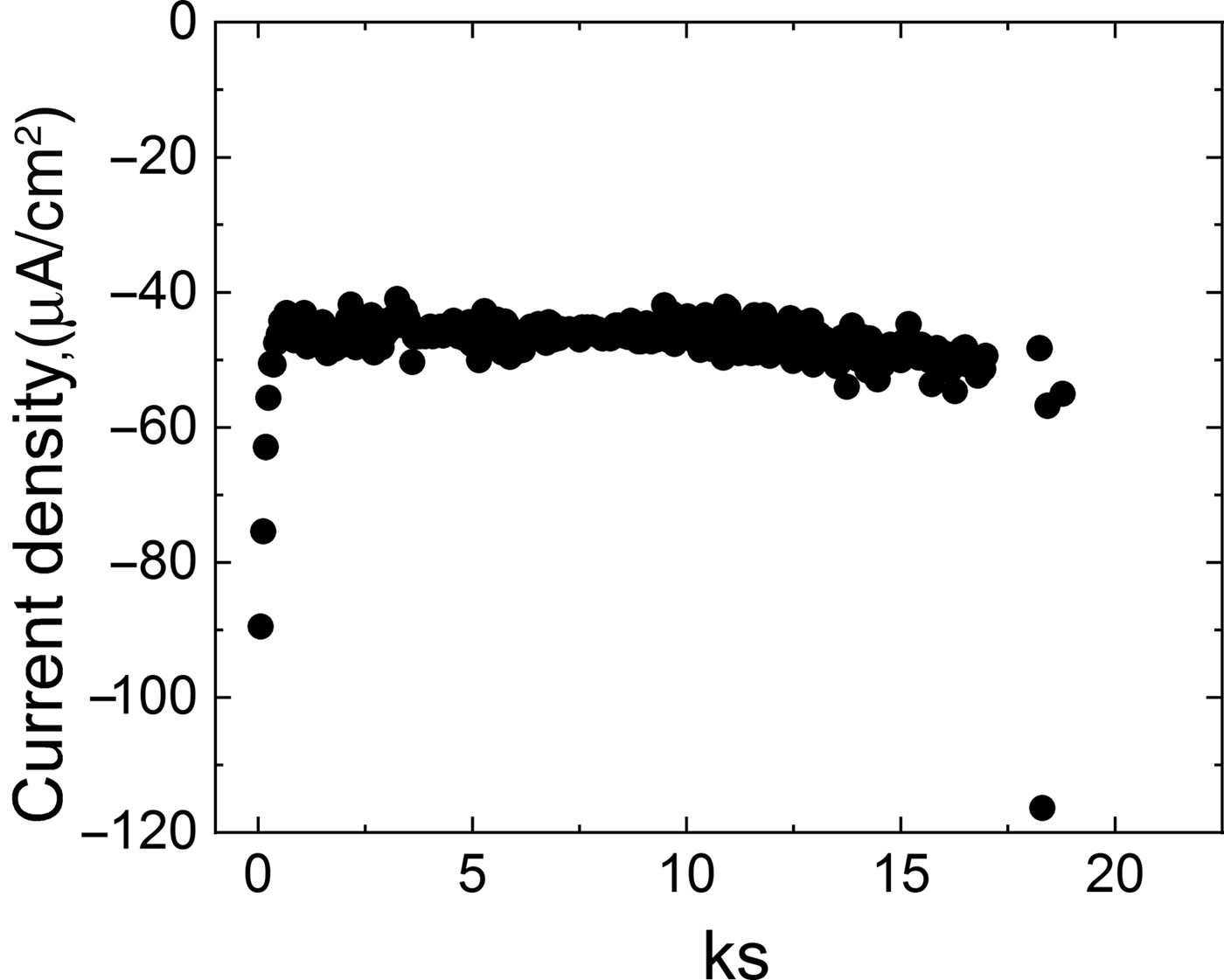
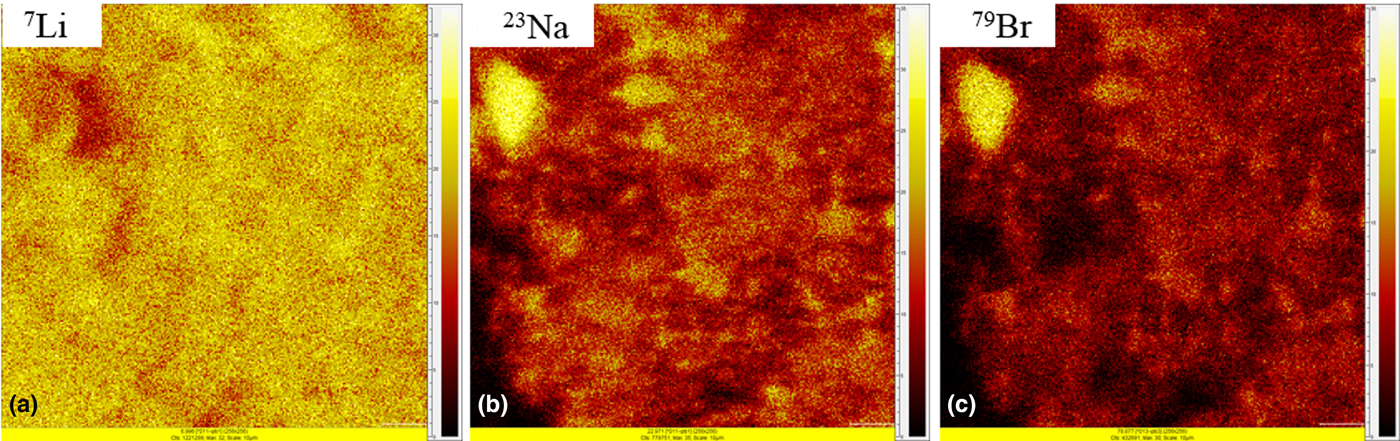
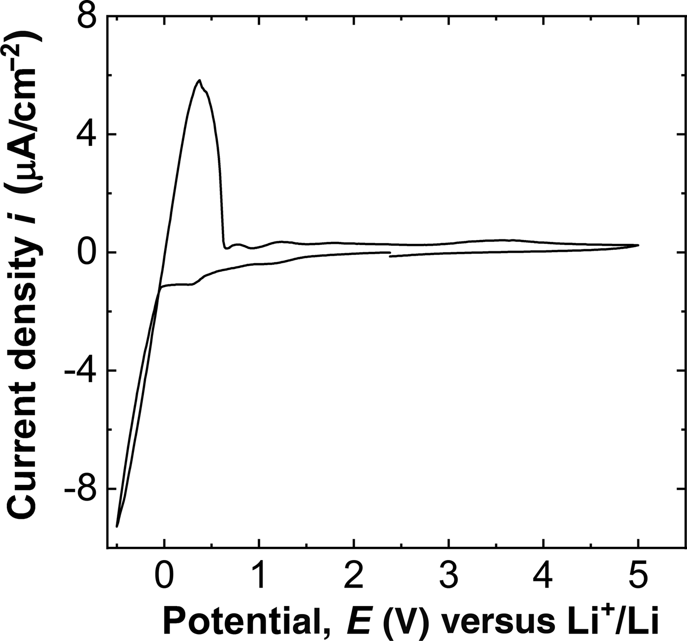
The main conductive ions in NaBr–LiBH4 system are determined by the combination of the electrochemical methods and TOF-SIMS measurement. Figure 3 shows the result of the potentiostatic measurement for Li/Mo asymmetrical cell using 15NaBr·LiBH4 as a solid electrolyte. The applied potential was −0.5 V (versus Li+/Li), resulting in the steady-state reduction current density of approximately −45 µA/cm2. The cell was short circuited at 17 ks, which is expected to be the result of the dendritic penetration of Li metal. In order to confirm the deposition species, the Mo foil was collected in a glove box and the surface of Mo foil at the solid electrolyte side was analyzed by TOF-SIMS measurement. Secondary ion images for 7Li+, 23Na+, and 79Br− in a same observed area are presented in Figs. 4(a)–4(c), respectively. It seems that the distribution morphologies of 23Na+ and 79Br− were similar and rather different from those of 7Li+. The fragmented solid electrolyte adheres to the surface of Mo foil as the inevitable contamination during the deconstruction of the Li/Mo cell. Therefore, the detected 23Na+ and 79Br− signals can be considered as the signals from the attached solid electrolyte. 7Li+ was mainly found in Na and Br deficit area, indicating that the detected Li is not the signal from the Li+ ions in the solid electrolyte. In conjunction with the result of potentiostatic measurement, the signal of 7Li+ indicates the deposited Li metal. The steady-state reduction of Li+ ions is possible under the constant mass transfer of Li+ ions in a solid electrolyte. Therefore, it can be concluded that the major conduction carrier in 15NaBr·LiBH4 is the guest Li+ ions. As shown in the CV curve of Li/Mo cell, a set of reversible redox peak at 0 V (versus Li+/Li) is clearly observed (Fig. 5). This result indicates that the Li dissolution and Li+ reduction reversibly occur at the interface of 15NaBr·LiBH4 and Mo electrode, which also supports the Li+ ion conduction in 15NaBr·LiBH4. Although small background current is observed, the clear decomposition current was not confirmed up to 5 V (versus Li+/Li) for the first cycle. However, as shown in Fig. S3 in Supplementary material, the repetition of the cycle results in the decomposition of 15NaBr·LiBH4. Therefore, the use of 15NaBr·LiBH4 with cathode materials such as LiCoO2 is rather challenging. The cathode materials with the moderate electrode potential (e.g., TiS2) can be expected to work in the all-solid-state cell with 15NaBr·LiBH4 as a solid electrolyte.
The results of DC potentiostatic measurements of the cell Li|15NaBr·LiBH4|Mo. The applied voltage was −0.5 V (versus Li+/Li).

Secondary ion images of the Mo foil electrode after potentiostatic reduction of the cell Li|15NaBr·LiBH4|Mo. The results for 7Li+, 23Na+, and 79Br− ions are presented in (a), (b), and (c), respectively.

Cyclic voltammogram for the cell Li|15NaBr·LiBH4|Mo at 423 K. Potential range was between −0.5 and 5.0 V (versus Li+/Li) at the sweep rate of 0.1 mV/s.

Once again, we emphasize that the most significant point of the guest Li+ ion conductors are the wider materials selectivity compared with the host Li+ ion conductors. The guest Li+ conductors are not restricted to the iodide compounds (NaI, KI), but NaBr was also demonstrated to work as the base material for Li+ conductor. The lack of the electrochemical stability at high voltage is the bottleneck point of 15NaBr·LiBH4, which can be derived from the thermodynamic stability of NaBr (340 kJ/mol corresponding to 3.5 V versus Li+/Li).[21] Therefore, if Li+ ions can be doped to the Li-free compounds with the high electrochemical stability, the solid electrolyte suitable for the practical use will be fabricated. This on-demand fabrication of the solid electrolytes based on the guest Li+ ions would be the novel materials development for the realization of high-performance all-solid-state batteries.
Conclusions
In the present work, in order to demonstrate that NaBr becomes a Li+ ion conductor, NaBr–LiBH4 system was fabricated and their ionic conduction properties were investigated by electrochemical methods and TOF-SIMS measurement. NaBr and LiBH4 form a solid solution, indicating that the guest Li+ ions occupy the Na+ sites and Br− ions are substituted with BH4− ions in NaBr. It was confirmed that Li metal was deposited on Mo foil after the potentiostatic reduction of the cell Li|15NaBr·LiBH4|Mo. A set of redox peaks representing the reversible reaction of Li ↔ Li+ + e− was clearly observed for the CV curve of the same cell composition. Based on these results, it can be concluded that the guest Li+ ions migrate in NaBr lattice.
Supplementary material
The supplementary material for this article can be found at https://doi.org/10.1557/mrc.2018.225.
Acknowledgment
This work was supported by JSPS KAKENHI Grant-in-Aid for Young Scientists, 18K14319 and The Foundation for The Promotion of Ion Engineering.