I. INTRODUCTION
Metallic thin films, unlike their coarse-grained bulk counterparts, often exhibit a time-dependent deformation behavior. This is especially the case with submicron films, the strength of which usually depends on the straining velocity. The knowledge of this strain-rate sensitivity is, therefore, essential for successfully designing microchips and microelectro-mechanical systems. Measuring the strain-rate sensitivity can also contribute to improve our scientific understanding of the deformation mechanisms of thin films.
The strain-rate sensitivity m is defined in the Mukherjee–Bird–Dorn equation as the power-law exponent, which relates the stress level experienced by a sample to the strain-rate imposed during deformation. It is, therefore, mathematically calculated as:
 $$m = {{\partial \ln \sigma } \over {\partial \ln \dot \varepsilon }}\quad .$$
Measuring the strain-rate sensitivity of macroscopic samples is a relatively common practice, especially in the field of severe plastic deformation and for nanostructured materials. Reference Meyers, Mishra and Benson1–Reference May, Höppel and Göken4 There is, on the other hand, only scarce data available on thin films—especially freestanding ones Reference Gianola, Warner, Molinari and Hemker5–Reference Wang and Prorok11 —mostly due to the lack of suitable experimental techniques. The approach chosen for the present work was to build upon one of the most robust methods available for thin films, the bulge test. Actually, this is not the first attempt to do so. As early as 1975 in USSR, Solonovich Reference Solonovich12 applied an increment of stress to a circular copper membrane during its transient creep relaxation. He observed an instantaneous change of the creep rate, whence he could calculate an activation volume. More recently, Alaca et al. Reference Alaca, Toga, Akar and Akin6 tested rectangular gold membranes at different strain-rates and calculated strain-rate sensitivities by comparing the measured yield strengths. While theoretically attractive, this approach requires the availability of several identical samples, which is hardly ever given for thin films, since a slight variation of the deposition parameters usually results in large changes in the microstructure and mechanical properties of the samples. The constant strain-rate method is also known to be very sensitive to thermal drift influences, Reference Maier, Durst, Mueller, Backes, Höppel and Göken13 as it relies on long lasting measurements of small deformations.
For these reasons, it appears more attractive to use the strain-rate jump method, first introduced by Weertman Reference Weertman14 in 1956, and nowadays commonly used on macroscopic samples in tensile, nanoindentation, Reference Maier, Durst, Mueller, Backes, Höppel and Göken13 compression, Reference May, Höppel and Göken4 and biaxial bulge Reference Cieslar, Karimi and Martin15 tests. In this method, the strain-rate is varied abruptly during loading, and the strain-rate sensitivity is evaluated from the sudden variation of stress.
II. BULGE TESTING
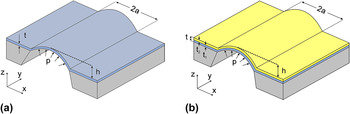
The self-built experimental setup used for this study has already been described elsewhere. Reference Merle and Göken16–Reference Merle and Göken18 It uses a large aspect ratio (4:1) rectangular membrane, which is pressurized from one side by nitrogen gas, see Fig. 1. For such a plane-strain bulge test configuration, it is possible to calculate the lateral stress and strain in the central area of the sample from the pressure p and the deflection h Reference Vlassak and Nix19,Reference Xiang, Chen and Vlassak20 :
 $${\sigma _{xx}} = {{p{a^2}} \over {2ht}}\quad ,$$
 $${\varepsilon _{xx}} = {{2{h^2}} \over {3{a^2}}} + {\varepsilon _0}\quad .$$
Schematic of the central section of a long rectangular membrane during bulge testing: (a) Single layer and (b) bilayer membrane.

In case a bilayer film is tested, and provided the mechanical properties of one layer are known from previous tests, it is possible to extract the contribution of the unknown layer from the overall deformation:
 $${\sigma _{xx,2}} = {{p{a^2}} \over {2h{t_2}}} - {{{t_1}} \over {{t_2}}}\left[ {{{{E_{{\rm{Y}}1}}} \over {1 - \nu _1^2}} \cdot {{2{h^2}} \over {3{a^2}}} + {\sigma _{0,1}}} \right]\quad ,$$
where E Y1 is the known Young's modulus, ν1 is the Poisson's ratio, and σ0,1 is the residual stress of the known layer of the sample.
III. SAMPLES
The samples consisted of freestanding and SiN x -supported gold membranes held within a 4 mm × 1 mm silicon frame. They were fabricated by standard lithographic techniques, starting from a silicon wafer, see for instance. Reference Merle and Göken18,Reference Xiang, Chen and Vlassak20,Reference Merle, Schweitzer and Göken21 The freestanding SiN x films were produced by micromachining by Silson Ltd. (Northampton, UK). The SiN x films were then coated with gold by thermal evaporation in a MED020 chamber (Balzers, Lichtenstein). The thicknesses of the gold films were in the range of 100–400 nm. Freestanding gold films were obtained by removing the SiN x substrate by CF4 reactive ion etching with a SI 591 system (Sentech Instruments, Berlin, Germany). Bilayer gold/SiN x films were also produced with the purpose of investigating the effect of a substrate on the mechanical behavior of gold. In this case, a thin chromium interlayer of 5–10 nm thickness was used to ensure a good adhesion of the gold layer to the SiN x throughout testing. To ensure valid comparisons between them, all gold films were deposited under the same conditions, at a constant rate of 3 Å s−1.
The microstructure of the gold films was mostly columnar, with a moderately wide distribution of grain sizes. No significant difference was observed between freestanding and SiN x -supported films. The mean grain size was measured by the line intersection method from plan-view backscattered electron micrographs to be in the range of 87–301 nm, scaling roughly with the thickness of the samples, as expected for evaporated metallic films. Reference Merle, Schweitzer and Göken21
IV. EXPERIMENTAL METHODS
A. Strain-rate jump tests
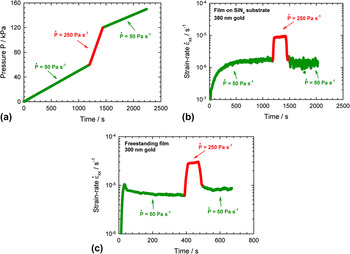
Strain-rate jumps were implemented in bulge tests by abruptly varying the pressurization rate, see Fig. 2(a). The pressurization was typically switched from 50 to 250 Pa s−1, which proved a large enough change to allow for a reliable evaluation of the strain-rate sensitivity. Care was taken that the pressurization jumps were carried out after significant straining, to avoid the initial strain-rate transient behavior in the elastic-dominated regime.
Effect of the variation of the pressurization rate on the strain-rate: (a) Pressure profile, (b) effect on the strain-rate of a SiN x -supported gold film, and (c) effect on the strain-rate of a freestanding gold film.

The effect of the pressurization jumps on the strain-rate is exemplarily shown in Figs. 2(b) and 2(c) for a freestanding film and a film on SiN x substrate. The variation of the pressurization rate leads to a similar increase in strain-rate—i.e., a factor of 5. After the reverse jump to the original pressurization rate, the strain-rate settles to a value close to—but not exactly equal to—its initial value. The reason for this small discrepancy is that the strain-rate actually slightly varies during straining, and here this change is magnified by the large strain increment accumulated during the fast pressurization segment.
One may wonder whether a constant pressurization rate is the most suitable loading function for achieving a constant strain-rate. For the ideal case of an elastic membrane without residual stress, it can easily be shown from Eqs. (2) and (3) that a constant strain-rate is achieved when the pressure is increased exponentially with time. In the other extreme case of an ideal plastic material, the same equations indicate that a square root function should be used to achieve a constant strain-rate. It is unfortunately not possible to solve the equation system (2) and (3) for an unknown material, as it would be required for predicting the most suitable load profile to use with an arbitrary sample. A linear function being a good trade-off between a square root and an exponential loading, it is reasonably well suited for a real elastic–plastic material. A large number of experiments performed by the authors on gold and copper films have confirmed that the strain-rate indeed varies only smoothly when the pressure is increased linearly over time.
Alternatively, one could rely on a fast feedback loop to continuously adjust the pressurization rate to keep the strain-rate constant. The implementation of such a hardware control Reference Alaca, Toga, Akar and Akin6 is, however, quite complex, and the feedback loop appears to be too slow to vary the strain-rate abruptly, making it less suited for the jump tests presented here.
Evaluation of strain-rate sensitivity
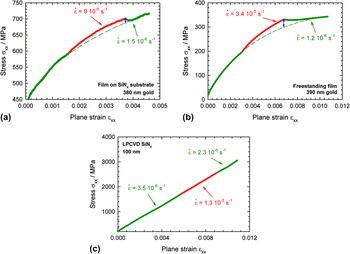
The evaluation of the strain-rate sensitivity begins with extrapolating the stress-strain curve at the slow deformation rate to the whole strain range, see Figs. 3(a)–3(b). This is performed by fitting a power-law function to the initial and final data, excluding the obvious transients. The strain-rate sensitivity of a sample is then obtained by evaluating the final strain-rate jump, i.e., comparing the stress level at the end of the fast loading with the value extrapolated for the slow loading rate. On the example shown in Figs. 3(a)–3(b), these values were taken at the blue double arrow. They were then used to calculate the strain-rate sensitivity from an approximation of Eq. (1):
 $$m \approx {{\ln {\sigma _{{\rm{fast}}}} - \ln {\sigma _{{\rm{slow}},\,{\rm{extrapolated}}}}} \over {\ln {{\dot \varepsilon }_{{\rm{fast}}}} - \ln {{\dot \varepsilon }_{{\rm{slow}}}}}}\quad .$$
Evaluation procedure of the strain-rate sensitivity from measured stress-strain diagrams of (a) gold film on SiN x substrate, (b) freestanding gold film, and (c) freestanding SiN x .

The evaluation procedure is less straightforward than for strain-rate jump tests on macroscopic samples, because thin films exhibit a very low failure strain (∼1%), which prevents reaching a fully plastic dominated deformation stage, associated with a constant stress level. Nonetheless, the effect of the pressurization rate jump on the stress level is clearly visible for both freestanding and SiN x -supported gold films, as illustrated in Figs. 3(a)–3(b), and can be evaluated by the method introduced above. The stress–strain diagram of SiN x —which is known to be strain-rate insensitive—is shown in Fig. 3(c) and does in comparison not show any discontinuity after the strain-rate jump, which clearly shows that the effects observed with gold are material related.
B. Creep tests
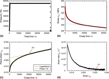
Constant load creep tests were implemented by keeping the pressure below the membrane constant for 12 h and continuously recording the deflection of the film. A representative test on a 300 nm thick freestanding gold film is shown in Fig. 4. Typically, the membrane creeps with time, which leads to an increase of the strain of the sample, see Fig. 4(c). Unlike with a constant stress creep test—which would require a feedback loop to be implemented—here the strain increase automatically leads to a decrease in stress, see Eq. (2). Since this stress decay—illustrated in Fig. 4(b)—is a consequence of the experimental bulge technique, it will not be discussed further here. The observed strain increase is more interesting, as it is a material-related effect that solely results from the deformation of the sample during the constant load solicitation. Looking at the corresponding data in Figs. 4(c)–4(d), it can be seen that the primary creep stage lasts for about 6 h and is then followed by steady-state deformation at a constant strain-rate. The experimental data were compared to the mathematical form of the classical logarithmic and Andrade (power 1/3) creep laws, Reference Cottrell22 see Fig. 4(c). It was found that the primary creep of the freestanding gold films is better described by a logarithmic law, just as it is the case for most creep tests performed at room temperature on bulk materials. This is usually interpreted as the progressive exhaustion of dislocations available for creep deformation. Reference Nabarro23
Creep test on a 300-nm freestanding gold film: (a) pressure profile, (b) stress variation, (c) strain variation, and (d) corresponding strain-rate.

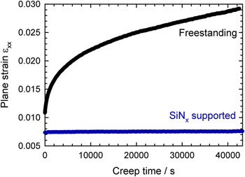
It is highly interesting to compare the behavior of a 200-nm gold film bonded to a 100-nm SiN x substrate to the previously discussed 300-nm thick freestanding gold film. The strain variation for both kinds of membranes is shown in Fig. 5. It can be seen that the SiN x -supported gold film is hardly affected by creep compared to the freestanding one, even though the pressure was much higher. While the steady-state deformation of the freestanding film occurs at a non-negligible strain-rate of about 10−7 s−1, that of the SiN x -supported sample is hardly measurable and at least two orders of magnitude lower. The reason could arguably be the different strength of the samples, as it is well known that mechanical passivation by a substrate results in a strengthening contribution to a film. Reference Merle, Schweitzer and Göken21,Reference Freund24–Reference Xiang and Vlassak26 Here the testing conditions were, however, chosen so that both samples were prestrained past their yield point, and the stress level in the SiN x -supported gold film exceeds the one in the freestanding sample by far (580 MPa compared to 220 MPa, both values after 12 h of testing). This undoubtedly shows that creep effects are intrinsically much larger in freestanding films.
Comparison of strain variation during creep tests between a freestanding gold film (300 nm thick) and a SiN x -supported gold film (200 nm on 100 nm SiN x ).

V. RESULTS
A. Strain-rate sensitivity of freestanding and SiN x -supported films
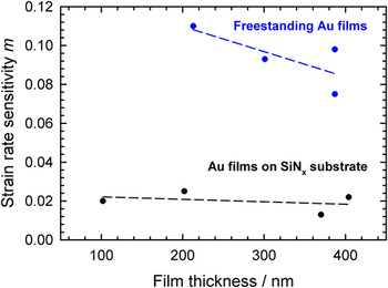
The newly introduced bulge test method was used to investigate the strain-rate sensitivity of freestanding and SiN x -supported gold films in the thickness range of 100–400 nm. The results are summarized in Fig. 6. For both freestanding films and films on a substrate, the strain-rate sensitivity appears to increase with decreasing film thickness. This trend is not surprising, as the mean grain size of the films scales with their thickness (see Sec. III Samples), and it is well known that a refinement of the grain size below a few microns is followed by an increase of the strain-rate sensitivity. Reference Meyers, Mishra and Benson1,Reference May, Höppel and Göken4,Reference Wang and Prorok11
Strain-rate sensitivity of gold thin films as measured by bulge tests.

The most striking feature from Fig. 6 is the large difference in strain-rate sensitivity between freestanding films (m = 0.094 ± 0.015) and films on a SiN x substrate (m = 0.020 ± 0.005). This strong difference indicates a change in deformation mechanisms. As the films are otherwise identical, it can only be attributed to the presence/absence of the bonding to a substrate.
It would be very instructive to establish if either condition corresponds to the bulk behavior of ultrafine-grained gold. A direct comparison of the measured strain-rate sensitivities with the bulk values unfortunately did not prove possible, due to the lack of such data in the literature. As a remedial, a thick film of 5 µm gold was grown by evaporation and tested by the strain-rate jump nanoindentation method of Maier et al. Reference Maier, Durst, Mueller, Backes, Höppel and Göken13 The indentation depth was limited to 10% of the film thickness, so as to avoid any influence from the substrate. This indentation depth is at the same time sufficient for the contact area to cover several tens of grains, which means that the results are expected to be pretty representative of bulk ultrafine-grained gold. The obtained value of m = 0.027 ± 0.006 is close to the bulge test results for gold films on SiN x substrate, hinting at a possible similar behavior for both kinds of samples. Such value is also close to the strain-rate sensitivity usually reported for bulk ultrafine-grained copper (m = 0.012–0.05), Reference Göken, Höppel, Hausöl, Bach, Maier, Schmidt and Amberger27,Reference Wei, Cheng, Ramesh and Ma28 a material quite similar to gold.
The strain-rate sensitivity measured on freestanding gold films is, in comparison, much higher, which is consistent with the results reported in the literature Reference Emery and Povirk8,Reference Jonnalagadda, Karanjgaokar, Chasiotis, Chee and Peroulis9 for submicrometer gold films tested in tension at similar strain-rates (m = 0.05–0.17). This increase compared to both bulk-like and SiN x -supported samples strongly suggests that the freestanding condition prompts a major change in deformation behavior, not yet described in the literature.
The quantitative evaluation of the strain-rate jump tests, however, does not provide any further insight into the deformation mechanisms, which must cause this difference. The conversion of the measured strain-rate sensitivities into stress exponents yields values greater than 10 in either case, which only hints at dislocation glide Reference Frost and Ashby29,Reference Meyers and Chawla30 being the dominant mechanism for the deformation of both freestanding and SiN x -supported films. While this clearly excludes diffusion as well as diffusion assisted grain boundary sliding [stress exponent n = 2 (Refs. Reference Lüthy, White and Sherby31 and Reference Van Swygenhoven and Derlet32)] as a significant mechanism for all conditions, it does not provide any clue about the different deformation behaviors.
Observing the samples after testing usually provides useful indications about the deformation mechanisms. Unfortunately, this did not prove possible to perform after the strain-rate jump tests, as they ended with the total failure of the specimen. However, creep tests were carried out, which had the advantage to magnify the time-dependent effects—as the load was kept constant during a longer period of time—and thus made differences between the samples more apparent.
B. Microstructural observations
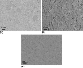
The surface of both freestanding and SiN x -supported samples was examined in the scanning electron microscope after the creep tests, see Fig. 7. While the SiN x -supported film did not show any qualitative difference between pre- and post-testing, the initially flat surface of the freestanding gold film strikingly experienced a strong roughening during the creep experiment.
Electron micrographs of the gold surface: (a) freestanding film after sample preparation, (b) freestanding film after creep test, and (c) SiN x -supported film after creep test.

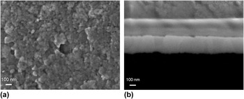
The focused ion beam (FIB) cross section shown in Fig. 8(b) evidences that the steps visible at the surface are localized at grain boundaries. It, however, seems from Fig. 7(b) that not all the grain boundaries are affected, but mostly the one oriented perpendicularly to the main tensile direction. This hints at a contribution of this mechanism to the elongation of the membrane. In details, the irregular height of the grains visible from the cross section shown in Fig. 8(b) also suggests that they have experienced plastic deformation. Next to or maybe as a consequence of this intragranular deformation, many grains appear to be tilted relative to their neighbors, with a section of their grain boundaries emerging above the surface, as best seen from the top-view micrographs in Figs. 7(b) and 8(a). Provided that the grain boundaries are not perfectly orthogonal to the film plane, this apparent grain boundary sliding is likely to prompt an increase of strain similar to the one observed during the creep test. Such effect has already been observed during fatigue testing of similar columnar gold films, Reference Merle and Göken18 albeit only at scarce locations where strain localization occurred. Creep results in comparison in widespread grain boundary sliding of lower magnitude.
Detail of the roughening of the freestanding gold film during creep: (a) top-view electron micrograph and (b) FIB cross section.

As previously mentioned, the fact that a SiN x -supported film does not show any evidence of roughening cannot be accounted for by its higher strength. A more fundamental influence of the substrate is that it prevents the out-of-plane motion of the grains and hence grain boundary sliding. This is not true if the adhesion of the film to the substrate is weak, but in the present case, the use of a chromium interlayer strongly promotes the adhesion between gold and SiN x . Another effect of the presence of the elastic SiN x substrate is that forces are balanced more evenly on the gold film, i.e., all forms of strain localization are prevented. All these reasons might explain the lower deformation rates achieved during creep testing.
VI. DISCUSSION AND CONCLUSIONS
The newly introduced strain-rate jump method for the bulge test allows quantitatively investigating the strain-rate sensitivity of thin films in the thickness range of 100–400 nm. Interestingly, the rate sensitivity measured for freestanding gold films is five times higher than for similar films bonded to a SiN x substrate, the behavior of which is in turn expected to be comparable with bulk ultrafine-grained gold. The surprisingly high time-dependence of the freestanding gold films was also observed during creep tests. The observation of the surface of the samples after the creep tests revealed a strong roughening in the case of the freestanding films, with steps appearing along grain boundaries. The fact that mainly grain boundaries orthogonal to the main tensile direction are affected by sliding strongly suggests that this mechanism contributes to the gradual elongation of the sample observed throughout the creep test. As the measured strain-rate sensitivity indicates that dislocation creep is the dominant deformation mechanism, it must be assumed that dislocation creep takes place within the individual grains and kinetically limits the apparent grain boundary sliding. A likely explanation is that a geometrical accommodation between grains is necessary before glide along a grain boundary can happen, and that this accommodation is provided by dislocation creep. This hypothesis is supported by the fact that neither the films attached to a substrate nor the bulk-like ultrafine-grained samples evidence the same apparent grain boundary sliding, presumably because the geometrical constraint imposed by the substrate or the neighboring grains is too high to allow for grain motion. In the freestanding films of this study, the out-of-plane motion of the grains is, on the other hand, possible because the highly columnar microstructure of the films and the presence of a free surface on both sides considerably lower these constraints. A similar grain boundary sliding intensity has been reported to occur in bulk samples during long-term nanoindentation, Reference Maier, Merle, Göken and Durst33 albeit only in the immediate vicinity of the free surface, where the geometrical constraints are also low.
The high strain-rate sensitivity measured in this study for freestanding gold films is in agreement with previous investigations on slightly thicker films. Reference Emery and Povirk8,Reference Jonnalagadda, Karanjgaokar, Chasiotis, Chee and Peroulis9 The present experiments albeit reveal that the mechanism responsible for it causes a roughening of the surface of the samples. Therefore, while it is usually argued that a high strain-rate sensitivity is beneficial to ductility by preventing strain localization, Reference Hosford34 in the case of freestanding thin films, this positive effect is largely mitigated by the creation of surface defects prone to act as crack initiation sites. Whether or not it is beneficial to the lifetime of the sample, the strain-rate sensitivity of a film is worth measuring, as its knowledge is necessary for precisely predicting the strength of the film under operating conditions. The proposed bulge test method provides a convenient way for achieving this goal and might, therefore, not only prove popular for research goals but also for industrial applications.
ACKNOWLEDGMENTS
The authors would like to thank Peter Pokrowsky from the Hochschule Kaiserslautern in Zweibrücken for providing access to the reactive ion etching facility used to make the gold membranes freestanding. They would also like to thank Petra Rosner from the group of Erdmann Spiecker at the University of Erlangen-Nürnberg for assistance with the evaporation device and Verena Maier from the Austrian Science Academy in Leoben for performing nanoindentation experiments. The authors also gratefully acknowledge the funding of the German Research Council (DFG), which, within the framework of its “Excellence Initiative”, supports the cluster of excellence “Engineering of Advanced Materials” at the University of Erlangen-Nürnberg.