Introduction
The studies on the short pulse demanding areas are arising popular day by day because of the need for generators that have narrow pulsewidth, high precision, high power, and high bandwidth. These properties are essential for numerous areas such as ground-penetrating radar (GPR) applications [Reference Omurzakov, Keskin and Turk1, Reference Wang, Zhang and Shi2] and UWB communications [Reference Wang, Tian, Liu, Li and Gao3]. Above mentioned features imply higher resolution and better imaging for radar applications, and high data-rate and increased security for UWB communications. In recent years, lots of studies were published for fast switching and short pulse generation applications. The avalanche transistors are low-cost, and provide narrow pulsewidth and large amplitude pulse output. They have long-life, rapid response, and stability. They are also easy to trigger and drive [Reference Wang, Zhang and Shi2–Reference Wu and Tian4]. Some nanosecond pulse generator designs employ single or multiple avalanche transistors with trigger stages, and some multi-transistor designs have cascaded or series-connected transistor topologies [Reference Omurzakov, Keskin and Turk1, Reference Wang, Zhang and Shi2]. Some sub-nanosecond pulse generators use step-recovery diodes (SRDs) [Reference Wong Choi, Joo Choi and Hoon Han5–Reference Valizade, Rezaei and Orouji7]. Short pulse generation and pulse shaping designs using avalanche transistors combined with SRDs were described in [Reference Yin, Pan and Zhang8, Reference Guo and Zu9]. Hence, the avalanche effect transistor is the one that offers promising solutions for the needs of areas such as UWB communications [Reference Wang, Tian, Liu, Li and Gao3, Reference Razavi, Aytur, Lam, Yang, Li, Yan, Kang, Hsu and Lee10, Reference Arafat and Harun-ur-Rashid11], radar systems [Reference Wang, Zhang and Shi2, Reference Xia, Liu, Guan and Fang12–Reference Ahajjam, Aghzout, Catala-Civera, Peñaranda-Foix and Driouach15] and many others.
There are many avalanche pulse generators described in the literature. In one study, number of transistors used vary from one to four [Reference Omurzakov, Keskin and Turk1] and their designs require a trigger signal to be applied at the base of BJTs. Thus, such designs also include a complicated and separate trigger circuitry and a high dc voltage to achieve avalanche effect (375 V). In this paper, design goal was to come up with a novel and simpler circuit topology different than those reported in the literature, and achieve a short pulsewidth and high power level suitable for UWB communications and GPR applications. The proposed circuit simply consists of two identical pulse generators using the avalanche effect of a BJT, driving the same 50-Ω common load. The presented circuit topology uses the mixing effect inherent to the avalanche transistors to broaden the pulse spectrum. Thus, output pulsewidth is reduced. The proposed circuit is the enhanced version of the one-transistor basic avalanche pulse generator circuit [Reference Chadderton16]. Proposed circuit topology is shown in Fig. 1. We performed measurements instead of simulations to design our circuits since the available Spice models do not include the avalanche multiplication mechanism. However, a new and simple method was developed in [Reference Dias17] to include the avalanche effect.
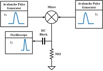
Block diagram of the proposed pulse generator circuit.

Single and two-transistor avalanche pulse generators
A block diagram of the proposed pulse generator circuit, composed of two identical avalanche pulse generators driving the same 50-Ω load resistor and a mixer, is shown in Fig. 1. A mixer is a three-port non-linear device or circuit which has two inputs and one output, and it performs frequency translation. Theoretically, when two signals are fed into a mixer, sum and difference frequencies as well as the harmonics of the input signals are generated at the mixer output. Assuming that when the input signals to the mixer are identical Gaussian-type pulses, the output signal should have a wider bandwidth than the bandwidth of a single input pulse due to the non-linear behavior of the mixer. As the Fourier transform dictates, broadening in spectrum translates into a shortened pulsewidth in time domain. Therefore, when the input signals are identical and have a pulsewidth of τ 1, the output pulsewidth τ 2 shall be less than τ 1. Any distortion in the output pulse waveform can be corrected by a suitable filter. So the goal of this paper is to demonstrate this effect by presenting novel circuit designs.
Before going into the final design, we shall proceed with the single transistor pulse generator namely the base circuit first, shown in Fig. 2. It uses a 2N2369A transistor as the active device. C1 and R1 are selected as 10 pF and 10 KΩ initially. C1 is charged to V CC through R1. V CC is the output of a custom-designed high voltage dc power supply based on a 555 IC and a MOSFET driver stage, whose dc output can be varied from 30 to 300 V. When the avalanche voltage level is achieved, Q1 goes into avalanche and discharges C1 rapidly. The discharge is in the form of a Gaussian pulse and taken from R3 through the output capacitor C2. The base circuit is in avalanche mode when V CC is 80 V, and is referred as self-triggered avalanche pulse generator since the base terminal of Q1 is not driven by any external signal, and is grounded through R2. For the circuit shown in Fig. 2 and all other circuits presented in this paper, a 300 MHz digital oscilloscope (Rigol Tech. DS2302A) was used to measure the time domain response, and a 30 GHz spectrum analyzer (Rohde&Schwarz FSV3030) was used to measure the frequency domain response. A higher bandwidth oscilloscope is required for accurate pulsewidth and pulse amplitude measurements. However, since it is not available, we decided to use the 30 GHz spectrum analyzer to verify the pulse broadening effect instead of measuring the shortened pulsewidth accurately.
Schematic of the single transistor self-triggered avalanche pulse generator.

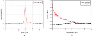
Figure 3(a) shows the output pulse in time domain. Pulsewidth and pulse amplitude were measured as 1.38 ns and 7.12 V. Measured pulse spectrum of the single transistor pulse generator circuit is shown in Fig. 3(b) and compared with the noise floor. For this measurement, a dc block was used to connect the circuit to the spectrum analyzer and the internal attenuation was set to 0-dB. Resolution bandwidth (RBW) and video bandwidth (VBW) are 3 MHz and 300 kHz, respectively. And these arrangements were kept the same for all measurements presented in this paper. As can be seen from Fig. 3(b), pulse spectral energy diminishes completely at about 7.5 GHz.
(a) Output pulse in time domain, and (b) in frequency domain, for the single transistor self-triggered avalanche pulse generator.

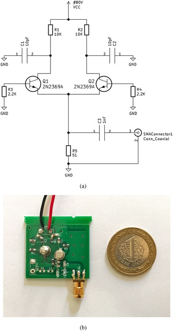
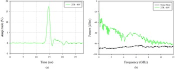
The basic circuit shown in Fig. 2 was improved with the addition of another transistor as shown in Fig. 4(a). Both transistors are connected in self-triggered mode through R3 and R4 base resistors, and V CC was set to 80 V as in the case of the single transistor circuit. Q1 and Q2 drive a common load resistor R5. Manufactured circuit is shown in Fig. 4(b). Figure 5(a) shows the output pulse in time domain. Pulsewidth and pulse amplitude were measured as 1.24 ns and 17.40 V, respectively. Measured pulse spectrum is shown in Fig. 5(b). As can be seen, pulse spectral energy is about 6 dB higher than the noise floor at 12 GHz, and the spectral power output appears to be higher than the single transistor base circuit.
(a) Schematic of the two-transistor avalanche pulse generator. (b) Photograph of the manufactured circuit.

(a) Output pulse in time domain, and (b) in frequency domain of the two-transistor avalanche pulse generator.

Figure 6 compares the pulse spectrums of single and two-transistor cases when V CC is 80 V. Output spectral power is about 16 dB higher at 3 GHz, about 18 dB higher at 6 GHz, and about 8 dB higher at 9 GHz. As can be seen, there is still some spectral energy at about 12 GHz. Broadening of spectral energy may be due to mixing of the two output pulses by Q1 and Q2. Although 2N2369A is a non-RF BJT, the circuit shown in Fig. 4 results in bandwidth enhancement and power amplification without using a separate broadband power amplifier. For some applications 80 V supply voltage may seem unrealistic. However, this voltage can easily be generated using a very compact power supply on the circuit board since very low currents are sufficient for the avalanche operation.
Comparison of spectrums of the single-transistor base circuit and the two-transistor circuit.

Pulse generator with a diode mixer
A new circuit was tested to see if there is a mixing effect when a mixer diode is placed at the output of the single transistor base circuit as shown in Fig. 7. The avalanche mode is triggered when V CC is 80 V. Mixer diode D1 (BAT1503W) is connected in parallel with the load resistor R3 through a coupling capacitor C2. D1 is forward biased through an RF choke L1 and a current-limiting resistor R4. Bias voltage is about 1.2 V to overcome the 0.7 V diode threshold voltage. The goal here is to generate a pulse due to the avalanche effect, and later generate harmonics of the input pulse due to nonlinearity of the mixer diode D1.
Schematic of the single transistor avalanche pulse generator circuit with a diode mixer.

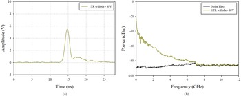
Figure 8(a) shows the measured pulse waveform and the output spectrum for the circuit in Fig. 7. Pulsewidth and pulse amplitude were measured as 1.46 ns and 5.56 V, respectively. As can be seen from Fig. 8(b), pulse spectral energy dies out at about 7 GHz completely. The expected result is to see some enhancement of the spectral bandwidth. However, results show that adding a diode mixer to the single-transistor base circuit did not provide any improvement in terms of broadening the spectrum. This may be due to passive nature of the diode mixer.
(a) Output pulse in time domain, and (b) output pulse spectrum of the base circuit with diode at the output for V CC = 80 V.

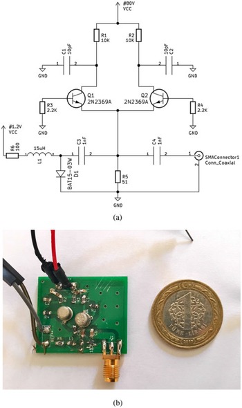
As the next step in our research, two avalanche pulse generators having 2N2369A transistors are connected through a common 50-Ω load resistor (R5) as shown in Fig. 9(a). The circuit includes a mixer diode D1 (BAT1503W) which is connected in parallel with the load resistor through a coupling capacitor C3. The diode performs the mixing action. It is forward biased through L1 and R6. Bias voltage is about 1.2 V. Both pulse generators are wired in self-triggered avalanche mode. V CC was set to 80 V which is the same as the two-transistor circuit case. The goal here is to perform mixing of two similar pulses generated by each 2N2369A through the mixer diode, and generate a broadband spectrum. A photograph of the manufactured circuit is shown in Fig. 9(b).
(a) Schematic of the two-transistor avalanche pulse generator with a diode mixer. (b) Photograph of the manufactured circuit.

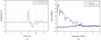
Output spectrum and time domain measurements of the two-transistor pulse generator with the diode mixer circuit is shown in Fig. 10(a). Pulsewidth and pulse amplitude were measured as 960 ps and 5.28 V. Measured pulse spectrum is given by Fig. 10(b). As can be seen, pulse spectral energy dies out at about 7.5 GHz completely.
(a) Output pulse in time domain, and (b) output pulse spectrum of the pulse generator with mixer diode for V CC = 80 V.

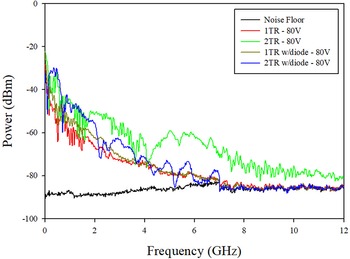
Comparison of the output spectrum for the single-transistor base circuit (1TR), two-transistor circuit (2TR), single-transistor with diode mixer (1TR w/diode), and the two-transistor with diode mixer (2TR w/diode) are given in Fig. 11.
Comparison of the output spectrums of tested circuits.

Results show that the two-transistor circuit produces the highest bandwidth, almost double that of the single transistor circuit, and higher output power. This may be due to mixing effect associated with Q1 and Q2. Broadened pulse spectrum also indicates shortened pulsewidth. Figure 11 also reveals that 1TR w/diode and 2TR w/diode circuits provide slight improvement in spectral power output compared to the single transistor base circuit below 6 GHz. However, beyond 7.5 GHz, output power is at the level of the noise floor. This can be explained as follows: there is definitely a mixing effect due to the diode. However, the diode appears as a parallel load next to the 50-Ω load resistor (R5) in Fig. 9(a), and since the mixer is passive by nature, output power for the spectral components generated by the nonlinearity of the diode is greatly reduced especially above 7 GHz.
Table 1 shows the output pulse amplitudes and pulsewidths for various cases when V CC is set to 80 V. Results of Table 1 indicate that the two-transistor circuit has shorter pulsewidth and higher pulse amplitude compared to the single transistor base circuit. And this improvement has also been verified in frequency domain by observing the enhanced bandwidth (12 GHz and beyond) and higher spectral power. There are two important questions that are to be answered now. Can we accurately measure a pulsewidth whose spectrum extends up to 12 GHz by using a 300 MHz oscilloscope? And which pulsewidth (for a Gaussian waveform) has about 12 GHz spectrum? Let's answer the second question first by running a simple code in Matlab. Simulations show that to obtain about 12 GHz spectrum from a Gaussian pulse, required pulsewidth must be less than 200 ps. And the required bandwidth of the oscilloscope to measure such a short pulse with reasonable error should be at least several GHz. So the answer to the first question is No. This was known from the beginning of this work, and for that reason we included the spectrum analyzer measurements for each case.
Comparison of the pulsewidth and pulse amplitude of tested circuits

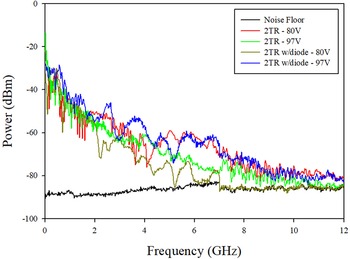
As one more step in the analysis, the effect of V CC was also investigated by increasing it to 97 V for the 2TR and 2TR w/diode circuits. Pulse spectrum measurements are shown in Fig. 12. Results show that when V CC is 80 V, 2TR circuit is the best. It provides higher output power and broadened pulse spectrum due to mixer effect provided by Q1 and Q2. When V CC increases to 97 V, output power of the 2TR w/diode circuit increases too, and its performance becomes about the same as the 2TR circuit for V CC = 80 V. This may be due to faster charging of capacitors C1 and C2 in Fig. 9(a), which hold the charge for the avalanche effect, and the output power increases in turn. Overall, the 2TR circuit outperforms the 2TR w/diode in terms of simplicity and having a lower V CC of 80 V. For the 2TR w/diode circuit for V CC = 97 V, pulsewidth and pulse amplitude are measured as 1.04 ns and 4.8 V, respectively. These measurements were 1.30 ns and 9.2 V for the 2TR circuit for V CC = 97 V.
Comparison of the output spectrums of two-transistor circuits for different V CC values.

As the final investigation, performance of the two-transistor circuit presented in this paper is compared with [Reference Omurzakov, Keskin and Turk1] and the comparison is shown in Table 2. Compared to [Reference Omurzakov, Keskin and Turk1], presented work provides shorter pulsewidth, a novel architecture, and a lower supply voltage.
Comparison of present work and a reference

There are many UWB systems that operate in the frequency band of 3.1–10.6 GHz such as wall imaging systems, GPRs, medical and communications systems. The presented circuit complies with the FCC spectral mask for the 3.1–10.6 GHz band as shown in Fig. 13. On the other hand, the spectral mask is not complied below 3.1 GHz. A simple high-pass filter following the pulse generator can be used to meet the FCC requirements below 3.1 GHz. Thus, some minor optimizations/modifications at the circuit level are required for UWB systems. For the proposed circuit, OOK-type modulation which is used in some UWB systems can easily be achieved by turning the pulses ON and OFF with the binary input data by the addition of a simple switching circuit.
FCC spectral mask applied to produced signals.

Conclusion
A novel, simple, and low-cost dual-transistor pulse generator circuit using self-triggered BJTs in avalanche mode with mixer effect have been designed and presented. The proposed circuit achieves higher output power without the use of a power amplifier, and provides a shortened pulsewidth and a broader spectral energy as compared to the reference single transistor design. All these properties make the presented circuit suitable for GPR, remote sensing, and ultra-wideband communications.
Acknowledgements
The authors thank to Prof. Korkut Yeğin at Ege University for the use of the RF laboratory.
Conflict of interest
None.
 Emrah Telli received his bachelor's degree in electrical and electronics engineering and biomedical engineering from the University of Karabük in 2020. He is currently a research assistant in Electrical and Electronics Engineering Dept. of the Muğla S׀tk׀ Koçman University. His working interests are high frequency electronic circuits, communication systems and biomedical applications.
 Bahad׀r S. Y׀ld׀r׀m received his Ph.D. from Arizona State University, Tempe, USA, in 1998. He is a full time professor at Muğla S׀tk׀ Koçman University. His main research areas are the design of compact antennas for mobile platforms, high-gain antennas, microwave noise generators, pulse generators, and UWB systems.