1. Introduction
Shock interactions affect the performance and reliability of flight vehicles from supersonic to hypersonic regimes. The strengths and positions of shocks vary dramatically as freestream Mach number
 $ M_\infty$
increases, which leads to different interference patterns and thus changes the heating/pressure loads on the flight vehicle (Sziroczak & Smith Reference Sziroczak and Smith2016; Urzay Reference Urzay2018; Cao et al. Reference Cao, Hao, Klioutchnikov, Olivier, Heufer and Wen2021; Li et al. Reference Li, Zhang, Tan, Jin and Li2022). To understand the fundamental mechanisms of shock interactions, extensive research was performed with canonical configurations, such as an oblique shock impinging on a bow shock (Edney Reference Edney1968; Wieting & Holden Reference Wieting and Holden1989; Bai & Wu Reference Bai and Wu2022), a double-wedge (Hu et al. Reference Hu, Gao, Myong, Dou and Khoo2010; Durna, Barada & Celik Reference Durna, Barada and Celik2016) and a double-cone (Tumuklu, Levin & Theofilis Reference Tumuklu, Levin and Theofilis2018; Fan, Hao & Wen Reference Fan, Hao and Wen2022). Transition criteria for different interference patterns were established on these canonical configurations, which successfully predicted the effects of geometric parameters and
 $ M_\infty$
on the transitions of shock interactions (Ben-Dor Reference Ben-Dor2007; Guan, Bai & Wu Reference Guan, Bai and Wu2020; Wang & Wu Reference Wang and Wu2021; Lin et al. Reference Lin, Yang, Hu, Wang and Jiang2023). Nevertheless, the shock interactions in air-breathing propulsion systems are rather complicated for vehicle flight over a wide range of speeds, the knowledge of which needs to be enriched to provide valuable guidelines for engineering applications.
The inward-turning inlet shows good ability to capture air over a wide range of speeds, thus it is commonly utilised in the air-breathing propulsion system of supersonic and hypersonic vehicles (Gollan & Smart Reference Gollan and Smart2013; Mohan & Skews Reference Mohan and Skews2013; Zuo & Mölder Reference Zuo and Mölder2019). Strikingly, taking a typical inward-turning inlet (Bisek Reference Bisek2016) as an example, the highly swept blunt leading edge of the inlet forms a V-shaped cowl lip (see figure 1 a), which generates complicated three-dimensional shock interactions, and affects both the internal and external flow of the inlet from supersonic to hypersonic regimes (Li, Li & Yang Reference Li, Li and Yang2021). To reveal the flow structures on the cowl lip and avoid the large cost of considering the entire inlet, Xiao et al. (Reference Xiao, Li, Zhang, Zhu and Yang2018) first proposed a model named the V-shaped blunt leading edge (VBLE; see figure 1 b), which consists of a pair of swept blunt leading edges and a crotch. Three primary types of shock interactions between the detached shocks (DS) generated by the swept blunt leading edges were identified in front of the crotch, i.e. regular reflection (RR), Mach reflection (MR) from different families, and regular reflection from the same family (sRR). Over the past five years, many subsequent studies were performed to better understand the complicated shock interactions from different perspectives. To provide an overview of recent developments on the VBLEs, these studies can be broadly grouped into the following areas: the effects of the geometric parameters of the VBLEs on the detailed interference patterns (Zhang et al. Reference Zhang, Li, Li and Yang2019a , Reference Zhang, Cheng, Shi, Zhu and You2023; Zhang, Li & Yang Reference Zhang, Li and Yang2021), heating/pressure loads (Li et al. Reference Li, Zhang, Wang and Yang2019, Reference Li, Jiang, Kang, Yin and Yan2024; Meng et al. Reference Meng, Fan, Xiong and Tao2019; Wang, Li & Yang Reference Wang, Li and Yang2021b ; Zhou et al. Reference Zhou, Li, Li, Xu, Shang and Yang2022; Kang et al. Reference Kang, Yan, Li, Li and Jiang2023a ) and flow oscillation characteristics (Wang et al. Reference Wang, Li, Zhang, Liu and Yang2018; Zhang et al. Reference Zhang, Li, Huang and Yang2019b , Reference Zhang, Li, Zhang, Huang, Wang, Yang, Wu, Liu and Cao2022a ). Moreover, some geometric optimisations (Wang et al. Reference Wang, Li, Zhang and Yang2020; Wang et al. Reference Wang, Li and Yang2021a ; Zhang et al. Reference Zhang, Wang and Li2022b ) and flow control methods (Kang et al. Reference Kang, Yan, Liu, Wang and Jiang2023b ; Li et al. Reference Li, Yan, Kang, Liu and Jiang2023; Liu et al. Reference Liu, Yan, Kang, Jiang and Sun2023) were also explored to modulate the heating augmentation resulting from the shock interactions.
Among the achievements to understand the intriguing shock interactions on the VBLEs, the transition of shock interactions plays a vital role. Zhang et al. (Reference Zhang, Li and Yang2021) found that the geometric parameters rather than the classical detachment and von Neumann criteria (Ben-Dor Reference Ben-Dor2007) govern the transition of shock interactions on the VBLEs. Theoretically, Zhang et al. (Reference Zhang, Li and Yang2021) established the transition criteria from RR to MR and from MR to sRR for the VBLEs with a sufficiently long swept blunt leading edge at
 $ M_\infty=6$
. The theoretical prediction method was further improved by Zhang et al. (Reference Zhang, Cheng, Shi, Zhu and You2023), since they found that the increase of
 $ M_\infty$
promotes the transition from MR to sRR. However, these previous studies were all concentrated in the hypersonic regime, in which the DS on the swept blunt leading edge easily reach a fully developed state with a constant value of stand-off distance before interference occurs. In reality, the development of DS itself becomes more important over a wide range of speeds, especially in the supersonic regime. The large changes in the shape of DS can lead to more intriguing shock structures, which have not been considered in previous studies.
Generally, DS grow gradually along the swept blunt leading edge with appropriate conditions, and eventually reach a fully developed state in supersonic and hypersonic flows, which yields a constant stand-off distance. In supersonic flow with a relatively lower
 $ M_\infty$
, the fully developed DS require a very long swept blunt leading edge, and the shock stand-off distance of the DS is much larger, which is difficult to meet in practice, as shown in the results at
 $ M_\infty= 4$
by Meng et al. (Reference Meng, Fan, Xiong and Tao2019). Thus the stand-off distance and the shapes of DS are usually immature when the intersection of the DS occurs in supersonic flow. Since the intersection of the DS is far away from the crotch, the DS are more likely to generate an RR in supersonic flow. Although multiple subtypes of RR may appear successively with increasing
 $ M_\infty$
(Xiao et al. Reference Xiao, Li, Zhang, Zhu and Yang2018), they are not yet identified theoretically in previous studies. Moreover, it is interesting to note that the longer swept blunt leading edge increases the stand-off distance of DS, while the higher
 $ M_\infty$
decreases it. This opposite trend implies that different lengths of the swept blunt leading edge can lead to various shock interaction patterns at the same
 $ M_\infty$
. Therefore, the length of the swept blunt leading edge is also a key factor for the shock interactions on the VBLEs over a wide range of speeds. The detailed transition process of shock interactions from supersonic to hypersonic regimes, and whether the transition criteria proposed by Zhang et al. (Reference Zhang, Li and Yang2021) apply, are still open issues. Due to the obvious importance of the fundamental mechanisms and applications over a wide range of speeds, it is necessary to systematically investigate the effects of
 $ M_\infty$
and the length of the swept blunt leading edge on transitions of shock interactions on the VBLEs.
Recognising that the shock structures change little at higher
 $ M_\infty$
(Anderson Reference Anderson2006), the shock interactions on VBLEs in the range
 $ M_\infty= 3{-}6$
are investigated using experiments and numerical simulations in the present work. Specifically, the shock structures varying with
 $ M_\infty$
and the length of the swept blunt leading edge are revealed, providing deep insight into the flow physics underlying the transitions of shock interaction. After quantitative analysis of the shock structures, transition criteria over a wide range of speeds for shock interactions on VBLEs are established to guide the design and optimisation of the V-shaped cowl lip. The remainder of this paper is organised as follows. The experimental and numerical methods are introduced in
 $\S$
2, detailed results and discussion on the shock interactions over a wide range of speeds are given in
 $\S$
3, and finally, conclusions are summarised in
 $\S$
4.
2. Model and methods
2.1. Geometrical model
As shown in figure 1, the VBLE consists of a pair of swept blunt leading edges with length
 $L$
and a crotch with rounding radius
 $R$
. The swept blunt leading edges and the crotch are tangentially connected with a half-span angle
 $\beta$
, all of which have the same blunt-leading-edge radius
 $r$
. The VBLE is symmetric about the
 $x$
–
 $z$
and
 $x$
–
 $y$
planes, while the coordinates
 $x$
,
 $y$
,
 $z$
and
 $\varphi$
denote the streamwise, transverse, spanwise and circumference directions, respectively. When the supersonic or hypersonic flow with Mach number
 $ M_\infty$
comes from the left, a pair of DS (i.e. DS
 $_1$
and DS
 $_2$
) generated by the swept blunt leading edges intersect in front of the crotch, which causes various shock interactions. To ensure that DS can be well developed and that the flow passing through DS is supersonic to permit shock interaction downstream,
 $\beta$
is theoretically restricted in a certain range (i.e.
 $M_\infty \sin\beta \gt 1$
). Detailed analysis about DS along the swept leading edge is provided in
 $\S$
3.4.1. Referring to previous studies (Xiao et al. Reference Xiao, Li, Zhang, Zhu and Yang2018; Zhang et al. Reference Zhang, Li and Yang2021), a typical configuration of the VBLE with
 $\beta=20^\circ$
,
 $r= 2$
mm and
 $R= 3$
mm is employed to focus on the transition of shock interactions from RR to MR at
 $ M_\infty=3{-}6$
. Note that
 $\beta$
is greater than the Mach angle in this wide range of speeds. It is well known that the length of the swept blunt leading edges is a key geometric parameter determining the shape of the DS, thus
 $L/r=15$
, 35 and 60 are examined to comprehensively understand the shock interactions induced by the DS over a wide range of speeds.
V-shape cowl lip: (a) inward-turning inlet adapted from Bisek (Reference Bisek2016) with modifications; (b) VBLE model.

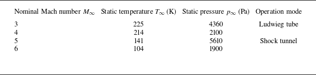
Freestream conditions of the FL-63 dual-mode wind tunnel.

2.2. Experimental set-up
Since the strength and position of the shock change significantly in the supersonic and hypersonic regimes, a series of experiments with a wide range of freestream conditions is conducted in the FL-63 wind tunnel (Gao et al. Reference Gao, Qian, Wang and Xin2020) of the Aerodynamics Research Institute of the Aviation Industry Corporation of China (AVIC). As listed in table 1, the FL-63 wind tunnel combines the operating modes of both the Ludwieg tube (Russell & Thomas Reference Russell and Thomas2012) and the shock tunnel (Li et al. Reference Li, Gao, Jiang and Yang2013), which can provide the freestream conditions of
 $ M_\infty= 3{-}6$
. A VBLE model with
 $L/r=35$
is selected as a typical example to verify the detailed shock structures over a wide range of speeds. A schlieren photographic system with a high-speed camera (pco.dimax cs1) is adopted to visualise the flow features near the crotch, and the exposure time is 1
 $\unicode{x03BC}$
s with framing rate 8000 fps. To obtain detailed flow features of the shock interactions, an enlarged model with magnification factor 4 relative to the aforementioned size (i.e.
 $r= 2$
mm) is adopted, and previous numerical results (Wang et al. Reference Wang, Li, Zhang, Liu and Yang2018; Xiao et al. Reference Xiao, Li, Zhang, Zhu and Yang2018; Zhang et al. Reference Zhang, Li and Yang2021) have shown that the magnification factor has little impact on the shock structures of VBLEs.
2.3. Numerical methods
Numerical simulations with variations in
 $ M_\infty$
and
 $L/r$
are performed using commercial software Fluent to provide a detailed transition process of the shock interactions. A three-dimensional Reynolds-averaged Navier–Stokes solver is employed based on the finite volume method. Roe’s flux difference splitting scheme is utilised for spatial discretisation of inviscid fluxes (Roe Reference Roe1981). The convective and viscous terms are discretised by a second-order upwind scheme and a second-order central difference scheme, respectively. Although the flow at the swept blunt leading edge of the VBLE appears to be in a laminar state according to the unit Reynolds number, a fully turbulent flow is assumed for the current simulations due to the enhancement of turbulence generation induced by the shock interactions in the crotch (Wang et al. Reference Wang, Li, Zhang, Liu and Yang2018). The Spalart–Allmaras turbulence model is chosen to model the turbulent flow (Spalart & Allmaras Reference Spalart and Allmaras1992). The equation of state for a calorically perfect gas is employed, and the molecular viscosity of the gas is assumed to obey Sutherland’s law. The numerical methods used in this paper are the same as those used in our previous studies (Xiao et al. Reference Xiao, Li, Zhang, Zhu and Yang2018; Li et al. Reference Li, Zhang, Wang and Yang2019; Wang et al. Reference Wang, Li, Zhang and Yang2020, Reference Wang, Li, Zhang and Yang2021b
; Zhang et al. Reference Zhang, Li and Yang2021, Reference Zhang, Wang and Li2022b
), which have been demonstrated as reliable for VBLEs.
Since the VBLE has two symmetry planes, as shown in figure 2, the one-quarter-domain model can be used to improve the computational efficiency. Thus the boundary conditions including the inflow, outflow, solid wall and symmetry at the
 $z= 0$
and
 $y= 0$
planes are adopted. Previous experiments have shown that the effect of slight shock oscillations on the time-averaged shock interaction pattern is generally minor (Wang et al. Reference Wang, Li, Zhang, Liu and Yang2018; Zhang et al. Reference Zhang, Li, Huang and Yang2019b
), and the use of symmetry planes has little impact on the primary shock structures (Wang et al. Reference Wang, Li and Yang2021a
; Zhang et al. Reference Zhang, Wang and Li2022b
; Kang et al. Reference Kang, Yan, Liu, Wang and Jiang2023b
; Liu et al. Reference Liu, Yan, Kang, Jiang and Sun2023). The inflow conditions are specified to be consistent with those of the experiments, whereas the outflow conditions are extrapolated from the interior flow. No-slip and isothermal wall boundaries are employed with fixed temperature 300 K. The entire computational domain is initialised by the inflow conditions for all cases. The numerical solutions are considered to converge when the variation in stagnation point pressure is kept below 0.1
 $\%$
, along with the stability of continuity and velocity residuals.
Computational domain and boundary conditions.

Previously, a VBLE with
 $R/r=45$
,
 $\beta=20^\circ$
and
 $L/r=35$
was examined in the KDJB330 shock tunnel of the University of Science and Technology of China, which provides schlieren images and pressure measuring points to quantitatively validate the numerical methods. As illustrated in figure 3(a), nine pressure transducers with full range 300 kPa (Kulite XCE-080-45A) are mounted with interval
 $\Delta\varphi=8^\circ$
along the centreline of the upper half crotch, and two pressure transducers with full range 50 kPa (Kulite XCQ-080-5A) are mounted along the centreline of the swept blunt leading edge. All pressure transducers have natural response frequency 20 kHz and accuracy
 $\pm$
0.5
 $\%$
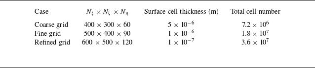
over the full range. Thus the experimental result is selected for the grid independence study. The inflow boundary conditions are consistent with the freestream conditions of the KDJB330 shock tunnel (Li et al. Reference Li, Gao, Jiang and Yang2013), which consist of a nominal freestream Mach number, pressure and temperature of 6, 1200 Pa and 121 K, respectively. Three sets of grids (i.e. coarse grid, fine grid and refined grid, listed in table 2) with an increasing ratio of the grid points greater than 1.2 in each direction (
 $N_\zeta$
,
 $N_\xi$
and
 $N_\eta$
represent the numbers of grid points around the crotch along the wall circumferential, normal and spilling directions, respectively; see figure 2) are tested. As shown in figure 2, the grids are radiated from the wall. The length of the opposite side of the wall is much larger than that of the wall along the
 $\eta$
direction, while the lengths of the opposite sides of the wall along other directions change slightly. Thus a maximum increasing ratio of the grid points is adopted along the
 $\eta$
direction. The fine and refined grids are performed mainly in the regions near the wall and around the crotch, to improve the resolution of the wall and the shock structures. As shown in figure 3(a), the shock structures simulated by the fine grid (the lower part) show a good resolution of the near-wall flow features, which are in good agreement with the experimental schlieren image (the upper part). Moreover, the wall pressure
 $p$
along the centreline is non-dimensionalised by the theoretical stagnation pressure
 $p_0$
of a cylinder in the same freestream conditions. The ratio
 $p/p_0$
obtained by the numerical simulations agrees well with the experimental data in figure 3(b), indicating the reliability of the numerical simulations. The relative error in the pressure peak is less than 0.85
 $\%$
when comparing the peak value obtained by the fine grid with that of the refined grid. Thus the fine grid is adopted for all simulations, in which the surface cell thickness is 1
 $\unicode{x03BC}$
m, and the total number of cells is 18 million. Comprehensive comparisons and detailed discussions on wave structures in a wide range of Mach numbers are given in appropriate locations in
 $\S$
3.1 to further validate the numerical results.
Comparisons between the experimental and numerical results: (a) experimental and numerical schlieren images; (b) surface pressure along the centreline.

Three sets of grids used in the grid convergence study.

3. Results and discussion
In the wide range of speeds, both
 $ M_\infty$
and the length of the swept blunt leading edge
 $L/r$
are key factors governing the shock interactions on VBLEs. To better understand the variations in shock structures at
 $ M_\infty= 3{-}6$
, the shock interactions on a typical VBLE with
 $L$
/
 $r$
= 35 are first presented. Then transition processes of shock interactions on VBLEs with variations in both
 $ M_\infty$
and
 $L$
/
 $r$
are discussed. Based on quantitative analysis of the shock structures, transition criteria for the shock interactions on VBLEs in the parameter space
 $(M_\infty,L/r)$
are finally established.
Three-dimensional shock surfaces on the VBLE with
 $L$
/
 $r$
= 35, and the Mach number contours in the
 $x$
–
 $z$
symmetry plane: (a)
 $ M_\infty$
= 3, (b)
 $ M_\infty$
= 4, (c)
 $ M_\infty$
= 5, (d)
 $ M_\infty$
= 6.

3.1. Effects of
 $ M_\infty$

An overview of the three-dimensional shock interactions on the typical VBLE with
 $L$
/
 $r$
= 35 at
 $ M_\infty$
= 3–6 is shown in figure 4, in which the three-dimensional shock surfaces are illustrated by translucent pressure isosurfaces, and the Mach number contours are displayed in the
 $x$
–
 $z$
symmetry plane. As the freestream encounters the swept leading edges of the VBLE, a pair of three-dimensional DS are first observed in figure 4. These three-dimensional DS get close to the swept leading edges gradually with the increase in
 $ M_\infty$
. As shown in figure 4(
 $a$
–
 $c$
), the three-dimensional DS intersect in the
 $x$
–
 $y$
symmetry plane, which forms a primary regular reflection along the intersection line between the DS near the
 $x$
–
 $z$
symmetry plane. As
 $ M_\infty$
increases, the regular reflection beyond the
 $x$
–
 $z$
symmetry plane is observed to transition into the Mach reflection gradually (see figure 4
 $c$
). Note that the three-dimensional shock interactions on the VBLE are significantly different from the classic two-dimensional cases (Ben-Dor Reference Ben-Dor2007). Similar transitions along the intersection line between shock surfaces were also found in three-dimensional shock reflections by Surujhlal & Skews (Reference Surujhlal and Skews2019). When
 $ M_\infty$
increases to 6 (see figure 4
 $d$
), a Mach stem (MS) forms in the
 $x$
–
 $y$
symmetry plane, and the previous regular reflection is replaced by a Mach reflection. To illustrate the three-dimensional shock interactions behind the DS, the shock surfaces of DS are removed in the enlarged views in figure 4. As shown in figure 4(
 $a$
–
 $d$
), the interactions between the three-dimensional DS produce transmitted shocks (TS). These transmitted shocks impinge on the wall, causing complicated flow structures near the crotch. Considering the lack of mature theories for three-dimensional shock interactions (Surujhlal & Skews Reference Surujhlal and Skews2019), more efforts on three-dimensional flow features of VBLEs should be made in the future. Nevertheless, to reveal the overall features near the crotch, the
 $x$
–
 $z$
symmetry plane of the VBLE is employed, which is naturally perpendicular to the intersection line between the three-dimensional shock surfaces. This special plane is of importance and is termed the analysis plane by Surujhlal & Skews (Reference Surujhlal and Skews2019) because the relations for oblique shock waves and their interactions can apply in the analysis plane. Thus the primary shock structures in the
 $x$
–
 $z$
symmetry plane of the VBLE are presented and discussed below.
Flow features in the
 $x$
–
 $z$
symmetry plane of the VBLE with
 $L$
/
 $r$
= 35: (a)
 $ M_\infty$
= 3, (b)
 $ M_\infty$
= 4, (c)
 $ M_\infty$
= 5, (d)
 $ M_\infty$
= 6.

Shock interactions in the
 $x$
–
 $z$
symmetry plane of the typical VBLE with
 $L$
/
 $r$
= 35 at
 $ M_\infty$
= 3–6 are shown in figure 5, where experimental schlieren images (upper half) are compared with numerical pressure isolines superimposed on Mach number contours (lower half). Although the Reynolds numbers (
 $Re$
) of the experiments are enlarged four times in the same freestream conditions (see
 $\S$
2.2), good agreement between the experimental and numerical results is achieved in terms of the wave structures, indicating that
 $Re$
has little impact on the shock interactions in this study. To show the detailed wave configurations near the crotch, local flow regions are enlarged in figure 5(
 $a$
–
 $d$
), and the sketches of flow features in the upper half are illustrated in figure 6. Since the
 $L$
/
 $r$
value of the VBLE is fixed, the shock interactions on the VBLE are affected mainly by the variations in
 $ M_\infty$
, which are discussed below.
As the freestream comes from the left in figure 5, a pair of growing DS from the upper and lower half-planes are first observed, and the stand-off distance
 $\delta$
decreases considerably with the increase in
 $ M_\infty$
. When
 $ M_\infty$
is in the range 3–5 (see figure 5
 $a$
–
 $c$
), the DS intersect directly, which forms a primary regular reflection (RR). Downstream of the intersection point (IP) of the DS, a pair of TS impinges on the wall of the VBLE. Of great interest, the impingement positions of TS change from the swept blunt leading edges to the crotch with the increase in
 $ M_\infty$
, leading to significant differences in the flow near the wall. Correspondingly, multiple subtypes of RR are generated on the crotch.
Sketches of shock structures for RR and MR: (a) RR
 $_1$
, (b) RR
 $_2$
, (c) RR
 $_3$
, (d) MR.

When
 $ M_\infty$
= 3, as shown in figures 5(
 $a$
) and 6(
 $a$
), the TS impinges on the swept blunt leading edge and induces a reflected shock (RS). This subtype of flow structure is categorised as RR
 $_1$
. A bow shock (BS) with the accumulated subsonic region in front of the crotch is formed. The high pressure behind the BS feeds upstream through the boundary layer, leading to a relatively small separation region and separation shock (SS). A transmitted shock (TS
 $_1$
) is emitted from the intersection point between the SS and BS to match the downstream pressure condition. As illustrated by the streamlines in figure 5(
 $a$
), the flow is deflected by the DS and TS, and subsequently converges inwards by the contraction of the crotch. The flows from the upper and lower half-planes collide near the stagnation point (S), creating a counter-rotating vortex pair (see the enlarged view in figure 5
 $a$
).
As
 $ M_\infty$
increases, DS with enhanced strength are closer to the wall, and the IP moves downstream due to the decrease in
 $\delta$
. Correspondingly, as shown in figures 5(
 $b$
) and 6(
 $b$
), the TS impinges on the junction between the swept blunt leading edge and the crotch (i.e. elbow) at
 $ M_\infty$
= 4, and intersects with the SS, generating a secondary RR. This subtype of flow structure is categorised as RR
 $_2$
. Interestingly, the TS impingement combined with the crotch curvature increases the adverse pressure gradient on the boundary layer, which affects the flow in the crotch. As illustrated by the streamlines in figure 5(
 $b$
), a part of the flow deflects upstream along the wall, and a larger flow separation with an obvious vortex extends to the swept blunt leading edge. The other part of the flow bounded by the TS
 $_1$
converges to the stagnation point, thus a counter-rotating vortex pair is formed downstream of the BS (see the enlarged view in figure 5
 $b$
).
For
 $ M_\infty$
ranging from 4 to 5, the impinging positions of the TS move away from the elbow towards the stagnation point. When the TS impinges on the BS, the previous secondary RR (i.e. RR
 $_2$
) is terminated. As shown in figures 5(
 $c$
) and 6(
 $c$
), the TS and SS are connected by an MS due to the downstream subsonic disturbance, and form a secondary MR. This subtype of flow structure is categorised as RR
 $_3$
. A supersonic jet is formed in the interactions between the TS and BS, which can be locally analogous to the structure of the classical Type IV shock interaction (Edney Reference Edney1968; Wieting & Holden Reference Wieting and Holden1989). The supersonic jet in RR
 $_3$
penetrates the subsonic flow and strikes the wall near the stagnation point. As illustrated by the streamlines in figure 5(
 $c$
), a large proportion of flow converges behind the MS, creating a pair of small vortices on each side of the stagnation point. Meanwhile, the separation regions on the straight branches shrink significantly (see the enlarged view in figure 5
 $c$
). As shown in figure 5, the IP between the DS moves towards the crotch with increasing
 $ M_\infty$
. When the IP reaches the BS, the disturbance from the downstream subsonic region terminates the original primary RR configuration, and changes the overall shock structures significantly. As shown in figures 5(
 $d$
) and 6(
 $d$
), DS intersect with an MS at the triple points (TP), thus a primary MR forms in front of the crotch at
 $ M_\infty$
= 6. The TS emitted from the TP impinges on the wall and causes a flow separation at the elbow. The intersection between the SS and the TS forms a regular reflection, which is embedded in the supersonic jet that is bounded by the shear layer emitted from the TP. As illustrated by the streamlines in figure 5(
 $d$
), the supersonic jets travel along the crotch and collide near the stagnation point. The combined streams are diverted forwards, rolling into a large counter-rotating vortex pair (see the enlarged view in figure 5
 $d$
).
In summary, the primary types of shock interactions between the DS (i.e. RR and MR) at different
 $ M_\infty$
fit into the classification scheme proposed by Zhang et al. (Reference Zhang, Li and Yang2021), while three subtypes of RR, depending on the impingement positions of the TS on the VBLE, are identified for the first time. As
 $ M_\infty$
increases, various shock structures, including RR
 $_1$
, RR
 $_2$
, RR
 $_3$
and MR, are exhibited successively on a given VBLE with
 $L$
/
 $r$
= 35. It must be emphasised that the DS grow gradually along the swept blunt leading edges before the occurrence of interferences at the same
 $ M_\infty$
, which can lead to various interference patterns. Shock interactions on the VBLEs with different
 $L$
/
 $r$
are discussed in the next subsection.
3.2. Effects of
$L$
/
$r$


An overview of the shock interactions in the
 $x$
–
 $z$
symmetry plane of the VBLEs with
 $L$
/
 $r$
= 15, 35 and 60 for
 $ M_\infty$
ranging from 3 to 6 is shown in figure 7. Sonic lines are superimposed on the numerical schlieren images to obtain a deep understanding of the shock structures and flow features near the wall. Although
 $M_\infty$
is the same for each row in figure 7, the shock stand-off distance and the shock angle of DS change significantly for different
 $L$
/
 $r$
. Thus various shock interactions can occur in the same speed regimes.
As shown in figure 7, the increase in
 $L$
/
 $r$
affects the shock interactions via the growth of DS, which is also influenced by
 $M_\infty$
. When
 $M_\infty$
= 3, the DS intersect directly to form RR, but the subtypes of shock interactions change with the increase in
 $L$
/
 $r$
(see figure 7
 $a$
–
 $c$
). The TS impinges on the crotch at
 $L$
/
 $r$
= 15, but it impinges on the swept blunt leading edge at
 $L$
/
 $r$
= 35 (see figure 7(a,b), respectively), thus the shock interaction patterns change from RR
 $_2$
to RR
 $_1$
. As shown in figure 7(
 $c$
), the shock interaction pattern maintains RR
 $_1$
with a further increase in
 $L$
/
 $r$
, but the impingement of TS moves upstream along the swept blunt leading edge, thus the RS can strike the middle of the BS. When
 $M_\infty$
= 4, the shock interaction patterns between DS also form RR, but the impingement of the TS moves away from the BS to the crotch for
 $L$
/
 $r$
= 15 and 35 (see figure 7(d,e), respectively), which causes the transition from RR
 $_3$
to RR
 $_2$
. The impingement of the TS at
 $L$
/
 $r$
= 60 moves further upstream along the crotch, but little change is shown in the shock interaction pattern, which maintains RR
 $_2$
. When
 $M_\infty$
= 5, the shock stand-off distance of DS is much smaller for
 $L$
/
 $r$
= 15 (see the left-hand column in figure 7), which provides the circumstances for the occurrence of MR (see figure 7
 $g$
). The position of the IP between the DS moves upstream with the increase in
 $L$
/
 $r$
, which becomes a critical parameter in determining the shock interference patterns. Once the IP is not affected by the downstream flow, the shock interaction patterns change from MR to RR
 $_3$
(see figure 7
g,h). As
 $L$
/
 $r$
increases to 60, the shock interaction pattern maintains RR
 $_3$
(see figure 7
 $i$
). Generally, the shock stand-off distance of DS increases rapidly with increasing
 $L$
/
 $r$
in the supersonic regime, whereas the increasing rate diminishes considerably in the hypersonic regime. As a result, the DS change slightly before their interferences at
 $M_\infty$
= 6 (see figure 7
 $j$
–
 $l$
), in which all shock interaction patterns are MR.
Numerical schlieren images for
 $M_\infty$
ranging from 3 to 6.

In summary, four types of shock interference patterns (i.e. MR, RR
 $_3$
, RR
 $_2$
and RR
 $_1$
) come out successively with increasing
 $L$
/
 $r$
in different speed regimes (see each row in figure 7), which appear in the opposite order to those of increasing
 $M_\infty$
with the same
 $L$
/
 $r$
(see each column in figure 7). It seems that the transition processes of shock interactions are similar, regardless of varying
 $L$
/
 $r$
or
 $M_\infty$
. When the shock interaction patterns are RR, TS acts as a bridge connecting DS and the downstream flow near the wall, which determines the transitions between subtypes of RR. When the IP is affected by downstream subsonic disturbance (i.e. IP meets BS), the transition from the primary RR to MR occurs, which is also demonstrated by Zhang et al. (Reference Zhang, Li and Yang2021). In other words, transitions of the shock interactions induced by varying either
 $L$
/
 $r$
or
 $M_\infty$
are closely related to the relative positions of the shocks, including IP, BS and TS. Thus quantitative analyses of these shocks are necessary to determine the transitions.
3.3. Variations in shock structures
Positions of IP, BS and MS: (a)
 $L$
/
 $r$
= 15, (b)
 $L$
/
 $r$
= 35, (c)
 $L$
/
 $r$
= 60.

As shown in figure 8(
 $a$
–
 $c$
), the distances from IP, BS and MS to the stagnation point S in the
 $x$
–
 $z$
symmetry plane (i.e.
 $d_{\textit{IP},S}$
/
 $r$
,
 $d_{\textit{BS},S}$
/
 $r$
and
 $d_{\textit{MS},S}$
/
 $r$
) are extracted from the numerical cases for
 $L$
/
 $r$
= 15, 35 and 60, respectively. Moreover, the time-averaged experimental data for
 $L$
/
 $r$
= 35 extracted from the high-speed schlieren images at
 $M_\infty$
= 3, 4, 5 and 6 are superimposed on figure 8(
 $b$
), in which the root mean square error (RMSE) values of the experimental data are presented as uncertainties because of the minor unsteadiness of the shock interactions (Wang et al. Reference Wang, Li, Zhang, Liu and Yang2018; Zhang et al. Reference Zhang, Li, Li and Yang2019a
). As shown in figure 8(b), the time-averaged experimental values of
 $d_{\textit{IP},S}$
/
 $r$
,
 $d_{\textit{BS},S}$
/
 $r$
and
 $d_{\textit{MS},S}$
/
 $r$
agree well with the corresponding numerical results, indicating the reliability of the numerical simulations. Note that the RMSE value of
 $d_{\textit{MS},S}$
/
 $r$
in the MR configuration is greater than the RMSE values of
 $d_{\textit{IP},S}$
/
 $r$
and
 $d_{\textit{BS},S}$
/
 $r$
in the RR configuration. The main reason in that the position of MS in the MR configuration is sensitive to the unsteadiness of the counter-rotating vortex pair downstream of MS (see figure 5
 $d$
). In contrast to the fluctuation of MS in the MR configuration, the primary shocks in the RR configuration are considered as steady cases because the interactions of the DS are not affected by the downstream flow (Zhang et al. Reference Zhang, Li, Li and Yang2019a
). Considering that the unsteadiness of flow separation in the RR configuration may affect the transition process of shock interactions on VBLEs with other
 $L$
/
 $r$
, more efforts on dynamic characteristics of the shock interactions should be made in the future. Since the RMSE values of
 $d_{\textit{IP},S}$
/
 $r$
and
 $d_{\textit{BS},S}$
/
 $r$
are much less than their time-averaged values, the variations in shock structures are determined mainly by the time-averaged results.
For the primary RR shown in figure 8,
 $d_{\textit{IP},S}$
/
 $r$
decreases distinctly with increasing
 $M_\infty$
for a given
 $L$
/
 $r$
, while
 $d_{\textit{BS},S}$
/
 $r$
slightly varies for different
 $M_\infty$
and
 $L$
/
 $r$
. At hypersonic speeds, Zhang et al. (Reference Zhang, Li and Yang2021) reported that the coalescence between the IP and the downstream disturbance (i.e.
 $d_{\textit{IP},S}$
/
 $r =$
 $d_{\textit{BS},S}$
/
 $r$
) is a good approximation for the transition from the primary RR to MR. It can be inferred that when the curves of
 $d_{\textit{IP},S}$
/
 $r$
and
 $d_{\textit{BS},S}$
/
 $r$
get close enough (i.e.
 $d_{\textit{IP},S}$
/
 $r \approx$
1.1
 $d_{\textit{BS},S}$
/
 $r$
) in figure 8, the original IP is disturbed by the downstream subsonic region behind the BS. Thus both IP and BS no longer exist, which is replaced by an MS. In other words, the transition from the primary RR to MR occurs. According to the work conducted by Zhang et al. (Reference Zhang, Li and Yang2021) at
 $M_\infty$
= 6,
 $d_{\textit{BS},S}$
/
 $r$
can be approximated as the shock stand-off distance
 $\delta _1$
/
 $r$
generated by the supersonic flow behind IP over a cylinder with radius
 $r$
. This approximate theoretical curve of
 $\delta _1$
/
 $r$
is plotted as a solid line in figure 8. Although the values of
 $d_{\textit{BS},S}$
/
 $r$
slightly vary above or below the theoretical curve of
 $\delta _1$
/
 $r$
due to different circumferential flows at subtypes of RR (see figure 5), the approximation by using
 $\delta _1$
/
 $r$
is sufficiently accurate to predict
 $d_{\textit{BS},S}$
/
 $r$
. Therefore, the position of the IP is mainly considered in
 $\S$
3.4.2 below to determine the transition from the primary RR to MR. Moreover, when MR occurs,
 $d_{\textit{MS},S}$
/
 $r$
slightly varies with increasing
 $M_\infty$
for a given
 $L$
/
 $r$
, as shown in figure 8.
The challenge is to quantitatively analyse the transitions between the subtypes of RR, because a complicated flow separation and SS are generated near the elbow (i.e.
 $\varphi \approx \pm$
70
 $^\circ$
; see figure 7) that affect the transitions significantly. Since the TS connects the DS and the downstream flow, the TS impingement positions
 $\varphi _{\textit{TS}}$
along the wall of the VBLEs in the upper half-plane for
 $L$
/
 $r$
= 15, 35 and 60 are shown in figure 9. Obviously,
 $\varphi _{\textit{TS}}$
always decreases with increasing
 $M_\infty$
. The RMSE values of
 $\varphi _{\textit{TS}}$
extracted from the experiments (i.e. cases
 $L$
/
 $r$
= 35 at
 $M_\infty$
= 3, 4 and 5) are much less than its time-averaged values (see figure 9
 $b$
), indicating that the position of TS is relatively stable during the experimental running time. For cases of RR
 $_1$
, the TS impinges on the swept blunt leading edge, and the separation region at the elbow is not affected. For cases of RR
 $_2$
, the TS impinges on the elbow, and intersects with the SS directly. A secondary RR is formed, and the flow separation region is enlarged due to the increased adverse pressure gradient. Thus
 $\varphi _{\textit{TS}}$
= 70
 $^\circ$
is considered as the threshold for the transition from RR
 $_1$
to RR
 $_2$
. According to the classic transition criteria for shock interactions (Ben-Dor Reference Ben-Dor2007), only the secondary RR is permitted in the interactions between TS and SS. However, TS and SS are observed to be connected by an MS when TS is affected by the downstream subsonic region near the stagnation point (see figure 7
 $d$
). Once the transition from the secondary RR to the secondary MR occurs (i.e. RR
 $_2$
to RR
 $_3$
), the subsonic region surrounded by BS and TS
 $_1$
suddenly increases, accompanied by the position changes in the TS
 $_1$
impingement position
 $\varphi _{TS_1}$
along the crotch. As shown in figure 9,
 $\varphi _{TS_1}$
decreases gradually and suddenly increases at approximately
 $M_\infty$
= 3.5, 4.5 and 4.8 in the upper half-plane, which correspond to
 $L$
/
 $r$
= 15, 35 and 60, respectively. These sudden changes are consistent with those of
 $d_{\textit{BS},S}$
/
 $r$
shown in figure 8, although it is difficult to distinguish this in figure 8. Moreover, the value of
 $\varphi _{\textit{TS}}$
is larger than that of the
 $\varphi _{TS_1}$
in the RR
 $_2$
domain, whereas the value of
 $\varphi _{\textit{TS}}$
is less than that of
 $\varphi _{TS_1}$
in the RR
 $_3$
domain. In other words, when
 $\varphi _{\textit{TS}}$
=
 $\varphi _{TS_1}$
the transition from RR
 $_2$
to RR
 $_3$
is initiated by the downstream subsonic disturbance. As shown in figure 9, the intersection between
 $\varphi _{\textit{TS}}$
and
 $\varphi _{TS_1}$
is approximately at 25
 $^\circ$
. Thus
 $\varphi _{\textit{TS}}$
= 25
 $^\circ$
is considered as the threshold for the transition from RR
 $_2$
to RR
 $_3$
. Moreover, when RR
 $_3$
occurs,
 $\varphi _{TS_1}$
slightly varies with increasing
 $M_\infty$
for a given
 $L$
/
 $r$
.
Impingement positions of TS and TS
 $_1$
: (a)
 $L$
/
 $r$
= 15, (b)
 $L$
/
 $r$
= 35, (c)
 $L$
/
 $r$
= 60.

As discussed above, a comprehensive understanding of the transition processes of the shock interactions on VBLEs is obtained by analysing a series of cases with different
 $ M_\infty$
and
 $L$
/
 $r$
. Thus it is possible to seek transition criteria for the shock interactions on VBLEs in a wider range of scenarios. Note that the hysteresis phenomena (Ben-Dor Reference Ben-Dor2007) may exist in the transition of shock interactions with the continuous variation in
 $ M_\infty$
or
 $L$
/
 $r$
. Due to the limitations of the present wind tunnel and the steady numerical simulations, hysteresis phenomena are not considered in this paper.
3.4. Transition criteria over a wide range of speeds
It has been shown in
 $\S$
3.3 that the development of DS along the swept blunt leading edge plays a crucial role in determining the shock interference patterns on VBLEs. Thus the shape of DS is examined first, with variations in both
 $M_\infty$
and
 $L$
/
 $r$
. Once the shape of DS is known in advance, it is easy to theoretically calculate the positions of IP and TS, which are essential preconditions for establishing transition criteria of the shock interactions in the parameter space
 $ (M_\infty,L/r)$
.
3.4.1. The DS along the swept blunt leading edge
The swept blunt leading edge can be regarded as an inclined cylinder against supersonic or hypersonic flow. Note that the incline angle is greater than the Mach angle for the present wide range of speeds. It is still difficult to analytically solve the development of DS over inclined cylinders because of the three-dimensional nature of the flow. As a typical example, the flow field on the swept blunt leading edge with
 $\beta$
= 20
 $^\circ$
and
 $M_\infty$
= 5 is shown in figure 10, where Mach number contours in the
 $x$
–
 $z$
symmetry plane and three-dimensional streamlines are used to illustrate the flow features. As shown in figure 10, DS is generated at the beginning of the inclined cylinder, and the flow behind DS is still supersonic. The streamlines passing through DS deflect at DS then smoothly curve upwards to accommodate the cylinder surface, indicating that a part of the flow spills from the sides of the inclined cylinder. Since the stand-off distance of DS gradually increases along the inclined cylinder, the flow spillage also changes. When the length
 $L_c$
of the inclined cylinder is sufficiently large, DS gradually reaches a fully developed state, in which a balance between the flow passing through DS in the
 $x$
–
 $z$
symmetry plane and the three-dimensional flow spillage is achieved. As a result, the fully developed DS is almost parallel to the inclined cylinder in the
 $x$
–
 $z$
symmetry plane. In other words, both the shock intensity and stand-off distance of DS no longer change in the
 $x$
–
 $z$
symmetry plane. Moreover, to ensure that
 $M_\infty \sin\beta \gt 1$
and the flow passing through DS is supersonic, the incline angle is theoretically restricted in a certain range, as pointed out by Zhang et al. (Reference Zhang, Li and Yang2021). In the present study,
 $\beta$
= 20
 $^\circ$
, which is larger than the Mach angle, meets all these restrictions for
 $M_\infty$
= 3–6.
The DS induced by a swept blunt leading edge with
 $\beta$
= 20
 $^\circ$
at
 $M_\infty$
= 5.

As shown in figure 10, the shape of DS at
 $L_c$
along the swept blunt leading edge in the
 $x$
–
 $z$
symmetry plane is parametrised by the local stand-off distance
 $\delta$
/
 $r$
and local shock angle
 $\beta _{\textit{DS}}$
, in which the origin of the coordinates
 ${\rm O}_c$
is located at the beginning of the swept blunt leading edge. The evolutions of
 $\delta$
/
 $r$
and
 $\beta _{\textit{DS}}$
along the swept blunt leading edge at
 $M_\infty$
= 3–6 are extracted from the numerical results and shown in figure 11. Here,
 $\delta$
/
 $r$
gradually increases with increasing
 $L_c$
/
 $r$
(see figure 11
 $a$
), whereas
 $\beta _{\textit{DS}}$
gradually decreases with increasing
 $L_c$
/
 $r$
(see figure 11
 $b$
). Theoretically, when
 $L_c$
/
 $r$
is sufficiently large, DS reaches the fully developed state, in which
 $\delta$
/
 $r$
asymptotically approaches a constant value of
 $\delta _e$
/
 $r$
, and
 $\beta _{\textit{DS}}$
asymptotically approaches the swept angle
 $\beta$
. As shown in figure 11,
 $M_\infty$
affects the asymptotic behaviour significantly, in which the asymptotic value is approached much faster for a large
 $M_\infty$
. Referring to the work by Zhang et al. (Reference Zhang, Li and Yang2021),
 $\delta _e$
/
 $r$
only depends on the vertical component of the incoming flow Mach number, which can be calculated in advance following the theoretical approximation proposed by Sinclair & Cui (Reference Sinclair and Cui2017). Note that the shape of DS changes little at sufficiently large
 $M_\infty$
, which is in accordance with the Mach number independence principle (Anderson Reference Anderson2006). In a wider range of scenarios, the shape of DS is determined by both
 $M_\infty$
and
 $L_c$
/
 $r$
. Therefore,
 $(\delta/r,\beta _{\textit{DS}})$
is expressed as
 \begin{equation} \left(\frac {\delta }{r}, \beta _{\textit{DS}}\right) = f\left(M_\infty , \frac {L_c}{r}\right). \end{equation}
Shape of DS in the
 $x$
–
 $z$
plane at
 $M_\infty$
= 3–6 with
 $\beta$
= 20
 $^\circ$
: (a) local stand-off distance
 $\delta$
/
 $r$
; (b) local shock angle
 $\beta _{\textit{DS}}$
.

3.4.2. Transition criteria
A generic VBLE model and the shock structures in the
 $x$
–
 $z$
symmetry plane are parametrised using the coordinate system shown in figure 12, where the origin of the coordinates O is located at the intersection of the generatrices of the swept blunt leading edges. The
 $x$
-coordinate of stagnation point S,
 $x_S$
, is obtained from the geometry:
 \begin{equation} \frac {x_S}{r} = -\frac {R}{r}\left(\frac {1}{\sin\beta } - 1\right). \end{equation}
Since the shape of DS is already known using (3.1), the positions of IP and TS generated from the intersection between DS can be calculated, which determines the transition of shock interactions.
As shown in figure 12, the IP in the primary RR is located on the DS and the
 $x$
-axis (i.e.
 $z$
= 0). Therefore, the stand-off distance of IP,
 $\delta _{\textit{IP}}$
, satisfies (3.1). One can obtain
 $\delta _{\textit{IP}}$
/
 $r$
and
 $L_c$
/
 $r$
simultaneously via combining (3.1) and the geometry relation
 \begin{equation} \frac {\delta _{\textit{IP}}}{r} = \left(\frac {L-L_c}{r}+\frac {R}{r\tan\beta }\right)\tan\beta . \end{equation}
The
 $x$
-coordinate of IP,
 $x_{\textit{IP}}$
/
 $r$
, is easily derived from the geometry relation, which can be written as
 \begin{equation} \frac {x_{\textit{IP}}}{r} = -\frac {\delta _{\textit{IP}}}{r\sin\beta }. \end{equation}
Thus the horizontal distance from IP to S,
 $d_{\textit{IP},S}$
/
 $r$
, is given by
 \begin{equation} \frac {d_{\textit{IP},S}}{r} = -\frac {x_S-x_{\textit{IP}}}{r} = \frac {\delta _{\textit{IP}}-R}{r\sin\beta } + \frac {R}{r}. \end{equation}
As discussed in
 $\S$
3.3, when
 $d_{\textit{IP},S}$
/
 $r$
 $\approx$
1.1
 $d_{\textit{BS},S}$
/
 $r$
, the transition from the primary RR to MR occurs. Since
 $d_{\textit{BS},S}$
/
 $r$
is assumed to be the shock stand-off distance
 $\delta _1$
/
 $r$
generated by the supersonic flow behind IP over a cylinder with radius
 $r$
(see figure 8), one can establish the transition criterion from the primary RR to MR,
 $f_{\textit{RR}_3-\textit{MR}}$
, when combining (3.5) with
 \begin{equation} \frac {d_{\textit{IP},S}}{r} = 1.1\frac {d_{\textit{BS},S}}{r} = 1.1\frac {\delta _1}{r} = f \left(M_\infty , \frac {L}{r}\right). \end{equation}
Considering that
 $d_{\textit{IP},S}$
depends only on
 $M_\infty$
and
 $L$
/
 $r$
,
 $f_{\textit{RR}_3-\textit{MR}}$
is expressed as
 \begin{equation} f_{\textit{RR}_3-\textit{MR}}\left(M_\infty , \frac {L}{r}\right) = 0, \quad d_{\textit{IP},S} = 1.1d_{\textit{BS},S} . \end{equation}
For a fully developed DS, Zhang et al. (Reference Zhang, Li and Yang2021) established a transition criterion
 $f_{\textit{RR}-\textit{MR}}$
(
 $ M_\infty$
,
 $R$
/
 $r$
,
 $\beta$
) at
 $ M_\infty$
= 6, in which the variations in
 $R$
/
 $r$
and
 $\beta$
are mainly considered. Essentially, both previous
 $f_{\textit{RR}-\textit{MR}}$
(
 $ M_\infty$
,
 $R$
/
 $r$
,
 $\beta$
) and present
 $f_{\textit{RR}_3-\textit{MR}}$
(
 $M_\infty$
,
 $L$
/
 $r$
) are based on the same mechanism that the transition from RR to MR is triggered by the downstream subsonic disturbance on the IP rather than the classical detachment and von Neumann criteria (Ben-Dor Reference Ben-Dor2007).
Sketches of shock structures in the
 $x$
–
 $z$
symmetry plane.

The subtypes of RR are determined by the position of TS in the
 $x$
–
 $z$
symmetry plane. As shown in the enlarged view in figure 12, TS is emitted from IP at angle
 $\sigma _{\textit{TS}}$
relative to the
 $x$
-axis. Since
 $\beta _{\textit{DS}}$
at IP is known, based on the classic two-shock theory (Ben-Dor Reference Ben-Dor2007),
 $\sigma _{\textit{TS}}$
can be calculated by
 \begin{equation} \sigma _{\textit{TS}} = \beta _{\textit{TS}}\left(M_\infty , \frac {L}{r}\right) - \theta _{\textit{DS}}\left(M_\infty , \frac {L}{r}\right), \end{equation}
where
 $\theta _{\textit{DS}}$
is the flow deflection angle across DS, and
 $\beta _{\textit{TS}}$
is the shock angle of TS in the vicinity of IP. To obtain the impingement point of TS on the crotch, TS is approximated as an oblique shock in the
 $x$
–
 $z$
symmetry plane, which is determined by
 \begin{equation} \frac {z_{\textit{TS}}}{r} = \left(\frac {x_{\textit{TS}}}{r} - \frac {x_{\textit{IP}}}{r}\right)\tan\sigma _{\textit{TS}}. \end{equation}
Since the crotch is a circular arc expressed in
 \begin{equation} \left(\frac {x_{\textit{TS}}}{r} + \frac {R}{r\text{sin}\beta } \right)^2 + \left(\frac {z_{\textit{TS}}}{r}\right)^2 = \left(\frac {R}{r}\right)^2, \quad \frac {x_{\textit{TS}}}{r} \gt -\frac {R\!\cos^2\beta }{r\!\sin\beta }, \end{equation}
one can obtain the TS impingement point (
 $x_{\textit{TS}}$
/
 $r$
,
 $z_{\textit{TS}}$
/
 $r$
) on the crotch by combining (3.9) with (3.10). After a coordinate transformation
 \begin{equation} \varphi _{\textit{TS}} = \sin^{-1}\left(\frac {z_{\textit{TS}}}{R}\right), \end{equation}
the TS impingement point on the crotch can be expressed as
 $\varphi _{\textit{TS}}$
. To assess the approximations of TS,
 $\sigma _{\textit{TS}}$
and
 $\varphi _{\textit{TS}}$
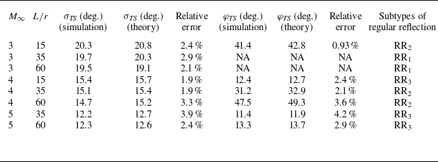
obtained from the numerical simulations are compared with those from the above theoretical procedures. As shown in table 3, the relative errors (i.e.
 $((\text{theory}-\text{simulation})/\text{theory})\times100\,\%$
) are all less than 5 %, indicating the feasibility of the theoretical method in predicting the TS position. As discussed in
 $\S$
3.3, when
 $\varphi _{\textit{TS}}$
is approximately 70
 $^\circ$
and 25
 $^\circ$
, the transitions from RR
 $_1$
to RR
 $_2$
and from RR
 $_2$
to RR
 $_3$
occur, respectively. Thus the transition criteria from RR
 $_1$
to RR
 $_2$
,
 $f_{\textit{RR}_1-RR_2}$
, and from RR
 $_2$
to RR
 $_3$
,
 $f_{\textit{RR}_2-RR_3}$
, depend only on
 $M_\infty$
and
 $L$
/
 $r$
, expressed as
 \begin{align}& f_{\textit{RR}_1-RR_2}\left(M_\infty , \frac {L}{r}\right) = 0, \quad \varphi _{\textit{TS}} = 70^\circ, \end{align}
 \begin{align}& f_{\textit{RR}_2-RR_3}\left(M_\infty , \frac {L}{r}\right) = 0, \quad \varphi _{\textit{TS}} = 25^\circ . \end{align}
Comparisons between the numerical and theoretical values of
 $\sigma _{\textit{TS}}$
and
 $\varphi _{\textit{TS}}$
. Here, NA means not applicable because TS impinges on the swept blunt leading edge.

3.4.3. Domains of shock interactions
It is worth noting that the above transition criteria
 $f_{\textit{RR}_1-RR_2}$
,
 $f_{\textit{RR}_2-RR_3}$
and
 $f_{\textit{RR}_3-\textit{MR}}$
are established based on the typical cases
 $L$
/
 $r$
= 15, 35 and 60. To verify the transition criteria in a wider range of
 $M_\infty$
and
 $L$
/
 $r$
, a series of new simulations, especially near the transition boundaries of the shock interactions, are conducted and marked as different symbols in figure 13. Theoretically,
 $L$
/
 $r$
should be larger than 7.6 to ensure that DS can intersect at the crotch according to the transition criterion
 $f_{\textit{RR}_3-\textit{MR}}$
, while
 $M_\infty$
should be larger than
 $1/\sin\beta$
(i.e. 2.9 for
 $\beta$
= 20
 $^\circ$
) to ensure that the fully developed DS can be achieved with a sufficiently large
 $L$
/
 $r$
. Thus the present study is focused on cases for
 $L$
/
 $r \gt 7.6$
and
 $M_\infty \gt 2.9$
. Good agreement between the transition criteria and the numerical results is achieved in the parameter space
 $(M_\infty,L/r)$
, which further demonstrates the reliability of the theoretical method for establishing the transition criteria.
Domains of the shock interaction at
 $R$
/
 $r$
= 1.5,
 $\beta$
= 20
 $^\circ$
.

As shown in figure 13, the transition criteria divide the parameter space
 $(M_\infty,L/r)$
into four domains, in which RR
 $_1$
, RR
 $_2$
, RR
 $_3$
and MR extend from the upper left to the lower right. Taking
 $L$
/
 $r$
= 80 as an example, the shock interference patterns are produced successively in the order RR
 $_1$
, RR
 $_2$
, RR
 $_3$
and MR with increasing
 $M_\infty$
. Taking
 $M_\infty$
= 4 as an example, the shock interference patterns are produced successively in the order MR, RR
 $_3$
, RR
 $_2$
and RR
 $_1$
with increasing
 $L$
/
 $r$
. The appearances of shock interference patterns are in opposite orders because the higher
 $M_\infty$
decreases the stand-off distance of DS, while the larger
 $L$
/
 $r$
increases it. When
 $L$
/
 $r$
is sufficiently large, DS is fully developed, thus the shock interaction patterns are mainly related to
 $M_\infty$
. For the fully developed DS (i.e.
 $\delta _{\textit{IP}}$
/
 $r$
=
 $\delta _e$
/
 $r$
and
 $\beta _{\textit{DS}}$
= 20
 $^\circ$
), the critical transition
 $M_\infty$
for
 $f_{\textit{RR}_1-RR_2}$
and
 $f_{\textit{RR}_2-RR_3}$
can be derived theoretically. Since
 $\delta _{\textit{IP}}$
/
 $r$
=
 $\delta _e$
/
 $r$
is known in advance for a given
 $M_\infty$
following the theoretical approximation used by Zhang et al. (Reference Zhang, Li and Yang2021),
 $x_{\textit{IP}}$
/
 $r$
is obtained using (3.4), while
 $\sigma _{\textit{TS}}$
is determined according to the classic two-shock theory (Ben-Dor Reference Ben-Dor2007) with the known condition
 $\beta _{\textit{DS}}$
= 20
 $^\circ$
. Based on
 $x_{\textit{IP}}$
/
 $r$
and
 $\sigma _{\textit{TS}}$
,
 $\varphi _{\textit{TS}}$
is determined by (3.9)–(3.11). When
 $\varphi _{\textit{TS}}$
is equal to 70
 $^\circ$
or 25
 $^\circ$
, the given
 $M_\infty$
is regarded as the transition
 $M_\infty$
according to
 $f_{\textit{RR}_1-RR_2}$
or
 $f_{\textit{RR}_2-RR_3}$
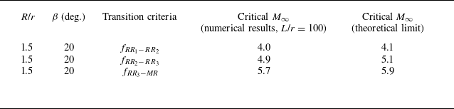
, respectively. The theoretically critical
 $M_\infty$
values for
 $f_{\textit{RR}_1-RR_2}$
and
 $f_{\textit{RR}_2-RR_3}$
with a sufficiently large
 $L$
/
 $r$
are listed in table 4. These theoretically critical
 $M_\infty$
values are slightly larger than the present results with
 $L$
/
 $r$
= 100, indicating the asymptotic behaviour of
 $f_{\textit{RR}_1-RR_2}$
and
 $f_{\textit{RR}_2-RR_3}$
(see figure 13).
Critical
 $ M_\infty$
for the transition criteria at sufficiently large
 $L$
/
 $r$
.

Note that the domain of primary RR terminates near
 $M_\infty$
= 5.7 in figure 13, while the domain of primary MR occupies the right-hand half of the parameter space bounded by
 $f_{\textit{RR}_3-\textit{MR}}(M_\infty,L/r)$
. When
 $M_\infty$
is sufficiently large, the shock interaction pattern no longer changes with increasing
 $L$
/
 $r$
. From the transition criterion
 $f_{\textit{RR}-\textit{MR}}$
(
 $M_\infty$
,
 $R$
/
 $r$
,
 $\beta$
) for a fully developed DS proposed by Zhang et al. (Reference Zhang, Li and Yang2021) at
 $M_\infty$
= 6, all present cases with
 $R$
/
 $r$
= 1.5,
 $\beta$
= 20
 $^\circ$
and a sufficiently large value of
 $L$
/
 $r$
are classified into the domain of primary MR at
 $M_\infty$
= 6, which is consistent with the present results shown in figure 13. Moreover, the original transition criterion
 $f_{\textit{RR}-\textit{MR}}$
(
 $M_\infty$
,
 $R$
/
 $r$
,
 $\beta$
) for fully developed DS proposed by Zhang et al. (Reference Zhang, Li and Yang2021) at
 $M_\infty$
= 6 can be extended to a wider range of
 $M_\infty$
. Specifically,
 $d_{\textit{IP},S}$
/
 $r$
is determined by (3.5) with the known condition
 $\delta _{\textit{IP}}$
/
 $r$
=
 $\delta _e$
/
 $r$
for
 $R$
/
 $r$
= 1.5 and
 $\beta$
= 20
 $^\circ$
at a given
 $M_\infty$
, while
 $\delta _1$
/
 $r$
is determined following the theoretical procedure adopted by Zhang et al. (Reference Zhang, Li and Yang2021) with the known condition
 $\beta_{\textit{DS}}$
= 20
 $^\circ$
. In accordance with Zhang et al. (Reference Zhang, Li and Yang2021), the critical
 $M_\infty$
for the primary RR to MR is obtained when
 $d_{\textit{IP},S}$
/
 $r$
=
 $\delta _1$
/
 $r$
. As listed in table 4, the theoretically critical
 $M_\infty$
is slightly larger than the present results with
 $L$
/
 $r$
= 100, indicating that the transition criterion of
 $f_{\textit{RR}_3-\textit{MR}}$
(
 $M_\infty$
,
 $L$
/
 $r$
) asymptotically approaches
 $f_{\textit{RR}-\textit{MR}}$
(
 $M_\infty$
,
 $R$
/
 $r$
,
 $\beta$
).
The transition criteria between subtypes of RR and the transition from RR to MR in the parameter space
 $(M_\infty,L/r)$
significantly elucidate the transition mechanisms for immature DS over a wide range of speeds. Although the phase diagram of shock interactions in figure 13 is based on a series of VBLEs with
 $R$
/
 $r$
= 1.5 and
 $\beta$
= 20
 $^\circ$
, the derivation process of the transition criteria
 $f_{\textit{RR}_1-RR_2}$
,
 $f_{\textit{RR}_2-RR_3}$
and
 $f_{\textit{RR}_3-\textit{MR}}$
can be generalised to a wider range of scenarios with other geometric parameters. Since multiple variables in both incoming flow and geometry are involved, the transition criteria become much more complicated and require further investigation. Considering that the hysteresis (Zhang et al. Reference Zhang, Xiao, Li, Zhu and Yang2019c
) may exist during the transition, more efforts on the hysteresis of shock interactions on the VBLE should be made in the future.
4. Conclusions
Shock interactions on VBLEs with different
 $L$
/
 $r$
(i.e. the length of swept blunt leading edge
 $L$
over the leading-edge radius
 $r$
) are investigated at
 $M_\infty$
= 3–6. The development of DS along the swept blunt leading edge depends on both
 $M_\infty$
and
 $L$
/
 $r$
, which plays a crucial role in determining the shock interaction patterns on VBLEs. The longer
 $L$
/
 $r$
increases the local stand-off distance of DS, while the higher
 $M_\infty$
decreases it. As a result, large changes in the shape of DS lead to intriguing shock interaction patterns on VBLEs. Various shock interaction patterns, including three subtypes of RR (i.e. RR
 $_1$
, RR
 $_2$
and RR
 $_3$
) and MR, are exhibited successively on a given VBLE with
 $R$
/
 $r$
= 1.5 and
 $\beta$
= 20
 $^\circ$
as
 $M_\infty$
increases, which appear in the opposite order to those of increasing
 $L$
/
 $r$
with the same
 $M_\infty$
. The numerical simulations show good agreement with the experimental results, both of which confirm the variations in shock interaction patterns.
The experimental and numerical results suggest that the transition processes of shock interactions by varying
 $L$
/
 $r$
or
 $M_\infty$
are similar, and both depend on the relative positions of shocks. The subtypes of RR are distinguished by the impingement position of TS emitted from the IP, in which
 $\varphi _{\textit{TS}}$
= 70
 $^\circ$
and 25
 $^\circ$
on the crotch are identified as thresholds for the transition from RR
 $_1$
to RR
 $_2$
, and from RR
 $_2$
to RR
 $_3$
, respectively. When the IP is affected by the downstream BS (i.e.
 $\delta _{\textit{IP},S}$
/
 $r$
= 1.1
 $d_{\textit{BS},S}$
/
 $r$
), the transition from RR
 $_3$
to MR occurs. Thus transition criteria (i.e.
 $f_{\textit{RR}_1-RR_2}$
,
 $f_{\textit{RR}_2-RR_3}$
and
 $f_{\textit{RR}_3-\textit{MR}}$
) of shock interaction patterns are established by theoretically calculating the positions of IP, TS and BS with the known shape of DS.
The shock interaction patterns on VBLEs in the parameter space
 $(M_\infty,L/r)$
can be theoretically determined by the present transition criteria, which shows good agreement with the numerical results for immature DS over a wide range of speeds. The parameter space
 $(M_\infty,L/r)$
is divided into four domains by the transition criteria, in which RR
 $_1$
, RR
 $_2$
, RR
 $_3$
and MR extend successively from the upper left to the lower right. When
 $M_\infty$
is sufficiently large, the shock interaction pattern no longer changes with the increase in
 $L$
/
 $r$
. When
 $L$
/
 $r$
is sufficiently large, DS reaches a fully developed state, leading to asymptotic behaviours of the transition criteria, in which the shock interaction patterns are mainly related to
 $M_\infty$
. These transition criteria serve as guidelines for the design of the cowl lip in the inward-turning inlet, thereby improving the performance of the inlet in the supersonic and hypersonic regimes.
Acknowledgements
The authors are grateful to the reviewers and editors for their valuable suggestions in improving the quality of the paper.
Funding
This work was supported by the National Natural Science Foundation of China (grant nos 12172354, 12388101, U21B6003 and 11772325) and the Strategic Priority Research Programme of the Chinese Academy of Sciences (grant no. XDB0620201).
Declaration of interests
The authors report no conflict of interest.