Introduction
This paper is an extended work of our work published in [Reference Hamid, Heberling, Junghähnel, Preussner, Gretzki, Pongratz, Hördemann and Gillner1]. A long-range automotive radar sensor is usually placed behind the bumper fascia or vehicle emblem [Reference Schnabel, Mittelstrab, Binzer, Waldschmitt and Weigel2]. This part of the vehicle acts as an additional radome to cover the antenna. This position has some drawbacks, especially when the bumper is painted with metal flakes. Multiple reflections between the antenna and the bumper occur and lead to inaccurate detection of arrival, reduced detection probability, or even false detections. Not only that, when water or snow covers the bumper and emblem, the transmission losses increase, and the detection range is eventually limited [Reference Schnabel, Mittelstrab, Binzer, Waldschmitt and Weigel2–Reference Vasanelli, Bögelsack and Waldschmidt4].
Another part of the vehicle that can be exploited for the placement of the radar module is the headlamp. The headlamps are at the height level of the bumper fascia, and the corner position enables an extending observation area to the sides of a car. Usually, the headlamp cover is made of polycarbonate and is thinner than the bumper fascia. Since standard polycarbonate has low permittivity and dielectric loss, the mentioned problems associated with the transmission losses and multiple reflections are reduced.
Some challenges related to the integration have to be addressed. First, the radar module (antenna and electronic units) must be able to withstand the high temperature of the headlamp. Then, the inclusion should not degrade the light distribution in the visible spectrum. Finally, the implementation should be cost-effective.
Several approaches have been proposed or filed as a patent. One of them, as in [Reference Yonemoto, Kohmura, Kurosawa, Watanabe and Yamamura5], proposed that the radar module is divided into two separate entities: the antenna unit and the electronic unit. The antenna is attached to the lamp unit of the headlamp, while the electronic is placed on the base of the headlamp housing. Several configurations have also been mentioned in [Reference Yonemoto, Kohmura, Kurosawa, Watanabe and Yamamura5], but the weakness is the need for a separate transmission line to connect the antenna and electronics. Since automotive radar nowadays operates in millimeter waves (76–81 GHz), the required transmission line will be very costly, especially when considering multi-TX-RX antennas (MIMO) configuration.
Within the framework of the Radar-Glass project, we investigate an efficient integration method of the radar module inside a headlamp for automotive radar application. Instead of treating the antenna and radar electronics as two separate entities, we design the antenna to be composed of a primary (feed) and secondary antenna (collimate and shape). The primary antenna can consist of waveguides, patches, slots, or sectoral-horn array and is integrated into the electronic unit. They are placed at the base of the headlamp cover and are invisible from the outside. The secondary antenna is a transparent offset planar reflector designed based on the Fresnel theory and the reflectarray concept to collimate or shape the radiation from the primary antenna. It is inserted in the space between the lamp and headlamp cover.
Antenna demonstrators have been fabricated. Here we report the radiation pattern and realized gain of the antenna, measured with and without the headlamp cover, under several configurations.
Setup, materials, and design
Setup
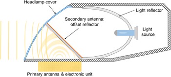
The setup, including the primary antenna, electronic unit, and secondary antenna, is shown in Fig. 1. The primary antenna and electronic unit are non-transparent components and have to be positioned outside the light path. They are preferably be placed at a hidden location, e.g., at the headlamp base. On the other hand, the secondary antenna is optically transparent and is introduced to enable a long-range radar (LRR) detection function. This secondary antenna is an offset reflector that reflects, collimates, and shapes the wave from the primary one. It is placed between the headlamp cover and the light source.
The setup in a headlamp: primary antenna, electronic unit, secondary antenna (offset reflector), headlamp cover, light bulb, and light source. Modified from [Reference Hamid, Heberling, Junghähnel, Preussner, Gretzki, Pongratz, Hördemann and Gillner1].

Optically transparent materials: substrate and thin-film conductor
The offset reflector is composed of a dielectric substrate coated with a transparent conducting oxide (TCO). The dielectric substrate is made of Makrolon polycarbonate material, with a measured complex permittivity of 2.73 + j0.016 (tan δ = 0.006) in the X-band. It has a low refractive index of 1.587 and high transmission percentage of 88% (for a thickness of 2 mm) [6]. The substrate is coated on both surfaces with Indium Tin Oxide (ITO). The front surface is patterned to get the required phase compensation (beam shaping), while the back surface is unpatterned to provide total reflection. ITO is one of the most widely used TCOs and has been used in numerous liquid crystal displays, touchscreen, OLED, and photovoltaic devices. With a thickness of less than 1 μm, a high transmission coefficient and a low DC surface resistance (<100 Ohm/square) can be achieved.
Planar offset reflector design
The introduction of the offset reflector structure as the secondary antenna is intended to convert a spherical wave from the primary antenna (feed) into a plane wave-front in the direction of maximum radiation. This offset reflector increases the directivity of the radiated wave from the primary antenna. A narrow beam radiation pattern (high gain antenna) is required for LRR application so that the radar sensor can detect objects in the distance of 200–300 m in front of the sensor. Commonly, this narrow beam is achieved by using an antenna array (e.g., series-fed patch arrays). The realization using a microstrip patch antenna array needs a relatively large RF substrate area. In our approach, the primary antenna is sufficient to have a low gain. Therefore, when it is implemented as a patch antenna, the required RF substrate is much less. The cost reduction associated with the smaller RF substrate can compensate for the additional cost, which comes from the production of the offset reflector.
The offset reflector increases the directivity of the feed antenna by compensating the phase of the incoming wave so that the effective radiation aperture at the surface of the offset reflector is larger than that of the feed antenna, and hence, a directional pattern is achieved.
The increase of the antenna directivity can also be achieved using a transmission-type structure to achieve a lens function structure. In the earlier phase of the RadarGlass project, a transmission-type surface (frequency-selective surface) that can increase the radiation directivity was also investigated. This transmission-type surface was coated using a TCO layer on a transparent substrate (i.e., the inner surface of the headlamp cover). The pattern was non-periodic patches with different patch sizes so that the transmission phase of the incoming waves is compensated differently. The outgoing waves have a quasi-uniform phase (larger radiation aperture).
Several flat samples of both transmission and reflection-type surfaces were fabricated and measured. Based on the loss measurement, it was found that the loss from the functional surface of the transmission type is up to 10 dB larger than the functional surface of the reflection type. The higher loss in the transmission-type surface is mostly due to the conductive losses in the TCO. It is actually predictable since more local resonants (stronger current flow) occur in each cell. TCO has a finite conductivity (typically a hundredth of the copper conductivity). Therefore, the impact of this conductive loss will be severe on the antenna performance [Reference Kocia and Hum7].
We, therefore, decided to use the reflection-type surface for later development. Another advantage of using the reflection type surface is the greater flexibility to place the radar module in the headlight and thus not to be dependent on the design of the different headlight cover. Two approaches to realize the offset reflector are pursued. The first one is based on the Fresnel theory, and the second one is based on the reflect-array concept.
Planar offset reflector based on Fresnel theory
Fresnel zone plate antenna composed of RF concentric opaque and transparent zones [Reference Guo and Barton8–Reference Gagnon, Petosa and McNamara11]. In a typical implementation using a PCB substrate, the opaque zones are the concentric circles that are printed on the front PCB surface. The RF transparent zones are the non-copper areas. To realize a normal incidence Fresnel reflector, a double-sided PCB structure is used. The PCB thickness is set to be a quarter of the medium wavelength. One side of this PCB structure consists of copper and non-copper areas to provide the opaque and transparent zones, while the other side is a continuous copper layer to provide a perfect reflection. Although the Fresnel zone plate does not transform the spherical incident wave smoothly (due to the zoning principle), it offers a low-cost and simple method to increase the directivity of the antenna.
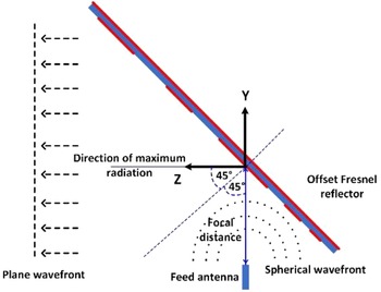
Due to the chosen offset configuration, the Fresnel zones at the front surface of the reflector are formed by ellipses. We used the open-ended waveguide WR-12 as the feed for the offset reflector. The layout of the feed and the reflector is shown in Fig. 2. In the design, we define the center frequency to be 76.5 GHz. The focal distance F is 2.6 cm, while the angle θo is 45°. The maximum radiation is toward the global Z-axis. On the reflector surface, a local coordinate with two orthogonal axes (XL–YL) is defined.
The layout of the open-ended waveguide WR-12 as the feed and the corresponding offset Fresnel reflector.

The ellipses are calculated through equations [Reference Guo and Barton8, Reference Leon, Herran, Munoz, Las-Heras and Hao9]:


where An and Bn are the semi-axis of the ellipses in the XL and YL-axes of the local coordinates on the reflector surface (not shown in Fig. 2), Cn is the position of the nth ellipses center along the local XL-axis, θ 0 is the angle between the propagation direction and the normal of the reflector surface, F is the focal distance, and λ is the free-space wavelength.
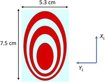
Figure 3 shows the shape of the Fresnel ellipses (Design I) in the local coordinate XL and YL-axes. Later, other designs (Design II-IV) will be introduced using the reflectarray concept. The focal point on the reflector surface is located at XL = 0 and YL = 0 at a distance of F from the open-ended waveguide aperture. The antenna is expected to have a minimum gain of 20 dBi. Based on our earlier simulations, three ellipses derived from equations (1)–(4) fulfills this gain requirement.
The design I: offset Fresnel reflector layout in the local XL-YL coordinates. The red ellipses are the transparent conducting oxide (TCO).

Planar offset reflector based on the reflectarray concept
Reflectarray combines the property of the antenna array and reflector [Reference Kocia and Hum7, Reference Nayeri, Yang and Elsherbeni12]. It comprises a feed antenna (e.g., patch, slot, open-ended waveguide) and a reflect-type surface, which is composed of unit-cells that function as phase-shifters. The antenna radiation direction can be engineered by calculating the required phase-shift at each unit cell and then by translating that phase-shift into a physical dimension and geometric profile of the cell.
We set the shape of the reflector to be a square with a dimension of 6 × 6 cm. The reflector is divided into 60 × 60 unit cells, where each cell has a dimension of 1 × 1 mm. The layout of the feed and the offset reflector based on the reflectarray concept is similar to the one shown in Fig. 2. The main difference is that the focal distance is now set to be 2 cm.
The required phase shift on the unit-cell must compensate for the additional phase due to the spatial delay (distance from the feed phase center to the corresponding unit-cell) and the progressive phase to the aperture that defines the maximum radiation direction. This phase shift can be calculated through [Reference Nayeri, Yang and Elsherbeni12]

where k 0 is the wavenumber at the center frequency fc = 76.5 GHz, R i is the distance from the feed phase center to the corresponding ith unit-cell, θ 0 is the intended maximum radiation in the elevation plane of the local coordinates (in our case θ 0 = 45°), x i and y i are the position of the ith unit-cell in the local coordinates, φ0 is the intended maximum radiation in the azimuth plane of the local coordinates, and ϕ 0 is a phase constant, which can be set to zero.
The calculated phase shift from equation (5) can range from 0 to 360°. To have an equivalent comparison with the previous Fresnel approach, the phase shift is grouped into an in-phase group (0–180°) and out-of-phase group (181–360°). In the fabrication, this relates to the unit cell that has TCO and no TCO coating.
Three designs (Design II-IV) are prepared to have an antenna with maximum radiation in three different directions, namely $\theta _1 = 0^\circ$ , $\theta _2 = 30^\circ$
 , and $\theta _3 = 60^\circ$
 . The TCO pattern of the design is shown in Fig. 4, while the angle directions, which denote the maximum radiation, are referred to in the layout, shown in Fig. 5. In Fig. 5, each reflector is fed with a single feed antenna. In practical implementation, e.g., MIMO array, each reflector can be fed with an array of single-element antennas to cover a broader azimuth angle from $\theta = 0^\circ$
 to $\theta = 90^\circ$
 .
Design II-IV: offset reflectors based on the reflectarray concept. Phase grouping is applied. The black color areas denote the areas coated with the transparent conducting oxide (TCO).

The intended direction of the maximum radiation from the offset reflector antennas, which are designed using the reflectarray concept (design II-IV).

Fabrication
The offset reflectors are fabricated by coating the transparent polycarbonate substrate with a very thin ITO layer. The front-coated surface is then patterned by using selective laser ablation.
ITO coating and laser ablation
This coating is performed at the Fraunhofer Institute for Organic Electronics and Plasma Technology, Dresden. The ITO films are grown on both sides of a Makrolon polycarbonate substrate by sheet-to-sheet processing in the pilot-scale in-line sputter coater. A conventional planar single magnetron system with oxide targets which is driven in a direct current (DC) sputtering mode, is used. The cathode length is 750 mm. The sputtering is done with a power of 3 kW and under a process pressure of 0.3 Pa.
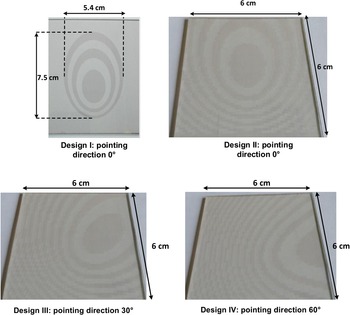
Following the previous step, laser ablation with high precision is applied on the front surface of the substrate to produce the fine pattern of the offset reflector. This process is done at the Fraunhofer Institute for Laser Technology, ILT Aachen. For that process, an ultra-fast, pulsed laser source is used in order to use multi-photon absorption to remove only the thin ITO layer while keeping the substrate intact. An additional advantage of the short pulses is the minimal heat input and thus a reduced induction of thermal and mechanical stresses. An optical system is chosen in that way, that only the top coating is structured without any damage to the backside. The fabricated offset reflectors for design I-IV are shown in Fig. 6 together with a typical resonant structure.
The fabricated offset reflector samples. Design I is based on the Fresnel theory, while Design II-IV is based on the reflectarray concept.

Feed antenna and headlamp cover integration
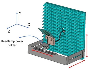
To investigate the influence of the headlamp cover on the antenna performance, we developed a holder so that the headlamp cover can be translated in three orthogonal directions and rotated around the antenna along the elevation (±45°) and azimuth (360°) axes. We use an open-ended waveguide WR-12 as the feed antenna (primary antenna) and Design I for the offset reflector (secondary antenna) in this study.
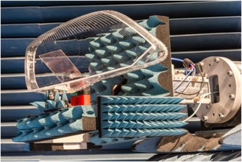
A headlamp cover made of polycarbonate material is placed in front of the offset Fresnel reflector (Design I). This setup is shown in Fig. 7. During the measurement, the holder will be covered with pyramidal absorbers to absorb unwanted scattering that can disturb the measurement. The demonstrator, which consists of an open-ended WR-12 and offset Fresnel reflector, is then measured in the compact range facility of the Institute of High-Frequency Technology (IHF), Aachen, as shown in Fig. 8.
Antenna and headlamp cover holder.

The antenna demonstrator and the headlamp cover are put in the tower of the antenna chamber.

Measurement results
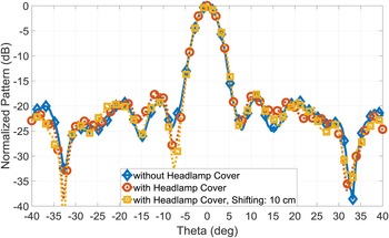
The impact of the headlamp cover on the antenna realized gain is shown in Fig. 9. Three cases are presented: without headlamp cover, with headlamp cover, and with a 10 cm translation of the headlamp cover along the X-axis (reference: Figure 7). Note that the original antenna position is in the middle area of the headlamp cover. All measurements using a headlamp cover are performed using an offset reflector from Design I (offset Fresnel reflector.)
Measured realized gain of the antenna, without and with the headlamp cover.

As they are shown in Fig. 9, in the range of 76–77 GHz (LRR application), the realized gain difference is less than 1 dB. The gain measurement accuracy in the compact range chamber itself is within ±1 dB. So, these results indicate that the headlamp cover does not degrade the antenna gain. The change of antenna position relative to the headlamp cover does not bring harm to the antenna gain, too. The gain stability observed from this measurement gives room for space flexibility when placing the antenna inside the headlamp.
In Fig. 10, the measured radiation pattern for those previous cases is presented in the azimuth (XZ) plane. The main beams are relatively unaffected, while the side lobes have just a slight difference. The beamwidth (HPBW = 4.8°) and sidelobe level (SLL < −18 dB) for those cases are almost the same. Although the shape of the headlamp cover is non-linearly curved, the azimuth radiation patterns are still quite stable. In addition, the elevation pattern is shown in Fig. 12.
Measured normalized azimuth pattern, without and with the headlamp cover.

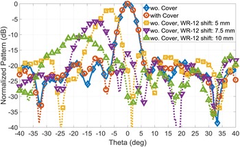
Measured azimuth pattern: WR-12 displacement along the X-axis.

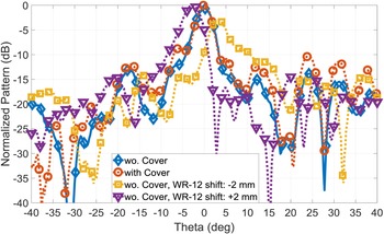
Measured normalized elevation pattern: without and with the headlamp cover, and feed shifting by ±2 mm (along the Z-axis).

The influence of the WR-12 feed relative position is subsequently investigated. The feed is moved away from the focal point along the X-and-Z axes, with reference to Figs 2 and 7 coordinate axes. Figure 11 shows the measured and normalized azimuth pattern for the case of translating the WR-12 feed along the X-axis.
For a feed translation of 5, 7.5 and 10 mm, the peak of the azimuth pattern shifts to −7, −12 and −18°, respectively. The maximum gain is also reduced by 1.8, 5.8 and 10.5 dB, respectively. The reduction is the consequence of being positioned outside the focal point, and hence the beamwidth gets wider. Due to the WR-12 shifting, the measured 3 dB beamwidths are 6, 8 and 12°, respectively. Without any shiftings, the beamwidth is 4.8°. Since the WR-12 and the offset Fresnel reflector are symmetric about the YZ-plane, the patterns are expected to be similar in the case of shifting the WR-12 toward the -X-axis. Assuming a gain reduction up to 6 dB is allowed, the limit distance for the WR-12 shifting can be set to 7.5 mm. This distance will also depend on the directivity pattern of the feeding antenna.
Figure 12 depicts the measured and normalized elevation pattern for four cases: without the headlamp cover, with the headlamp cover, a feed translation of −2 mm along the Z-axis, and a feed translation of +2 mm along the Z-axis. The normalized antenna pattern without both the headlamp cover and the WR-12 shift serves as the reference.
The elevation pattern in the case of without and with the headlamp cover is relatively similar, especially in the main lobe. The discrepancies are noticeable for the side lobes, especially at higher elevation angles. Since the antenna polarization lies in the elevation plane, its pattern is more sensitive to the non-symmetric curve of the headlamp cover in the YZ-plane.
For a 2 mm feed-shift toward the +Z axis, the maximum beam points at $\theta = {-}3^\circ$ without a decreased gain. On the other hand, by shifting it to the opposite direction (the minus Z-axis), the pattern has a maximum at $\theta = + 3^\circ$
 and suffers a reduction on the realized gain by 2.9 dB and an increase of side lobes. This investigation indicates that the feed shifting in the Z-axis is limited.
The results from Figs 11 and 12 suggest that we can put more antennas along the X-axis than the Z-axis for feed array implementation. If the allowable gain reduction is 3 dB (instead of 6 dB), the usable area for placing the antennas can be defined to be 12 × 4 mm.
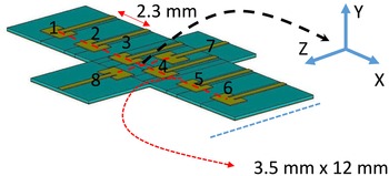
An example of a feed array configuration using patch antennas is shown in Fig. 13. The offset Fresnel reflector is not shown for clarity. There are six patch antennas along the X-axis and two patch antennas along the Z-axis. The patches are inset-fed and matched to the 50 Ohm input impedance (S 11 < −10 dB) within the 76–77 GHz range. Along the X-axis, the distance between the center of the adjacent patches is 2.3 mm (0.58λ0), while that along the Z-axis is 3.5 mm (0.9λ0). The distance 2.3 mm along the X-axis is chosen since we expect that the difference in gain between the patch element in the middle and the edge is about 3 dB. If the allowable difference is about 6 dB or higher, the distance can be set larger, e.g., 3 mm. In this example, the focal distance F is kept constant. The dielectric substrate is from Rogers 3003, with relative permittivity of ɛr = 2.9 and loss tangent tanδ = 0.0013.
Patch array configuration to replace the single WR-12 feed.

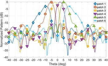
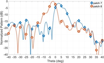
The simulated azimuth and elevation patterns (normalized) of the antennas are shown in Figs 14 and 15, respectively. The realized gain for patch antennas #2, #3, #4, and #5, are very similar, while the realized gain reduction for patch antennas #1 and #6 are less than 3 dB. The beamwidths of the antennas are slightly smaller compared to those using the WR-12 feed.
Simulated azimuth pattern, using patch 1–6 as the feed.

Simulated elevation pattern, using patch 7–8 as the feed.

In general, the radiation pattern behavior, either using WR-12 or patch antenna as the feed, is relatively similar. The decision to use the proper feed also depends on other factors, such as losses, ease of fabrication, cost, and integration to the electronic unit and packaging.
Investigation on the manufacturing tolerances and their influences on the antenna pattern has not been performed yet, but it will be carried out in a later research stage. Since the Fresnel pattern is obtained by using laser ablation, the dimensional and shape changes of the pattern due to this process are negligible compared to the wavelength. The critical factor will be more from the mechanical perspective: how to maintain the stable position of the feed and the offset angle of the reflector due to the car vibration. These aspects should be tackled in further development.
In the subsequent discussion, the measurement results of the offset reflectors from Design II-IV are presented. These offset reflectors are intended to illuminate radar objects along the azimuth (horizontal) plane. Each reflector is fed with one open-ended waveguide WR-12 antenna. Note that in this design, each has a different beam direction. The offset reflector from Design II, II, and IV should have a maximum beam at the azimuth angle of 0, 30 and 60°, respectively.
In future work, the single WR-12 feed antenna will be replaced with a patch-array configuration (Fig. 13) so that the azimuth coverage at least from 0 to 90° (Fig. 5) can be covered. Design II-IV will be patterned and arranged using one common substrate (see Fig. 4), and each will be fed with a (different) patch array configuration that represents different radar range applications: long (LRR), medium (MRR), and short-range radar (SRR). So, one transparent dielectric substrate will contain three offset reflectors, where each reflector will be fed with a patch array of a different number of elements and different operational frequencies.
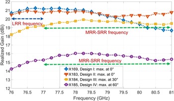
The measurement setup, similar to Fig. 7 (but without the headlamp cover), is used. Each design (Design II-IV) is measured separately and fed with a single WR12 feed. Figure 16 shows the measured realized gain from Design II-IV. The result from Design I is inserted here for comparison. The offset reflectors from Design I and II have maximum radiation toward the forward direction (angle 0°) and are intended to be used for the LRR application. Therefore, they have a higher gain at 76–77 GHz. The upper band, from 77 to 81 GHz, is the frequency band for the MRR and SRR applications. It is to detect objects that are located at a wider angular position nearby the radar sensor. The offset reflector from Design III has a realized gain of above 19 dBi, while the reflector from Design IV has a realized gain of above 15 dBi. Both designs III and IV have a center frequency of around 78–79 GHz since they are intended to be used for medium MRR and SRR applications.
Comparison of the measured realized gain from Design I-IV.

The decrease of the realized gain for the offset reflector from Design III and IV is due to the reduction of the radiation contribution from the first and second ellipses. In Fig. 4, to achieve an azimuthal shift of the maximum radiation direction (XZ-plane of the global coordinate), the unit cells experience an angular rotation along the Z L-axis and translation along the Y L-axis of the local coordinate, respectively. Since the reflector size is fixed at 6 × 6 cm, the areas of the first and second ellipses are cut. Design IV suffers a larger gain reduction since the area of the first ellipse is cut by more than 50%.
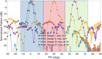
Figure 17 shows the normalized radiation pattern from Design II-IV. For comparison, the normalized pattern from Design I is added. As they are shown here, Design I and II have a maximum radiation direction at angle 0°. There is a slight shift of the maximum radiation for Design II due to a minor misalignment between the WR-12 feed and the offset reflector. The same reason is applied for the shift of maximum radiation from Design IV, too. For all designs, the side lobes levels are below −10 dB.
Comparison of the measured horizontal (azimuth) pattern.

Note that the results shown in Fig. 17 are based on the measurement setup using a single (not array) feed configuration. Therefore, there seems like several blind spots existed between the angle 0 and 30°, 30 and 60°, and above 60°. When the offset reflectors from Design II-IV are fed with an array configuration (see Fig. 13), there will be multiple beams that cover the whole angles 0–90°.
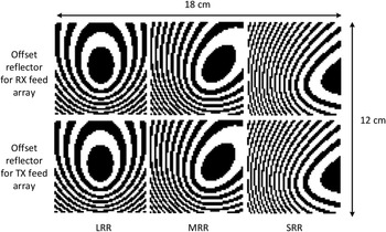
In the following, an arrangement of the offset reflector capable of operating in a MIMO scenario is discussed. Figure 18 depicts the proposed offset reflector configuration. There are three TX-RX pairs of offset reflectors for different range and angular requirements (LRR, MRR, and SRR). Each offset reflector is fed with a specific TX or RX feed array. Since the current RFICs typically have 3 TX and 4 RX channels, if we deploy four RFICS: one for LRR, one for MRR, and two for SRR, the number of TXs and RXs that are used as the feeding for the offset reflector are: 3 TXs and 4 RXs for LRR, 3 TXs and 4 RXs for MRR, and 6 TXs and 8 RXs for SRR. The number of feeding antennas for SRR is set to be larger to obtain a higher angular resolution of the detected objects.
The proposed offset reflector arrangement for long (LRR), medium (MRR), and short-range radar (SRR) applications.

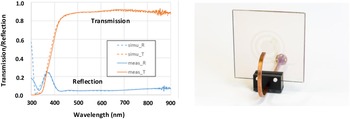
To this end, the key point of the effective radar module arrangement within the headlamp is the use of a transparent reflector to collimate or shape the wave from the primary antennas so that they can be integrated directly with the electronic unit. The transparent reflector can be designed based on the Fresnel theory or reflectarray concept. In the allocated frequency range 76–81 GHz, the current packaging dimension of the radar module is still too large to be placed in the proximity of the light bulb. Therefore, it should be placed at the base of the headlamp cover and hidden from the light transmission. The feed arrays are directly connected to the RFIC, and then the radiation from the feed array is collimated or shaped by the offset reflector, which is introduced in the space between the light bulb and the headlamp cover. To avoid light intensity degradation due to the insertion of the offset reflector, the reflector should be made of transparent materials with a transmissivity of higher than 80%. The measurement of the optical transmission of the reflector has been performed at the Fraunhofer Institute for Organic Electronics and Plasma Technology, Dresden. Figure 19 shows the simulated and measured optical transmission and an example of one of the earlier reflector prototypes. As it is shown in this figure, the waveguide feed and the supporting structure at the back of the reflector are clearly visible.
Simulated and measured optical transmission of the reflector and one example of the earlier prototypes.

Conclusion
The integration of a millimeter-wave antenna inside a headlamp for automotive radar application is investigated, and the influence of the headlamp cover on the antenna performance is studied. The headlamp cover does not degrade the realized gain and radiation pattern of the antenna since it has a low thickness, low relative permittivity, and low loss factor. It can perform as a radome that protects the sensors from snow and rain due to the heat radiation from the light source. An antenna demonstrator, composed of WR-12 as the feed and several transparent offset reflectors as the secondary antennas, has been fabricated and measured. It has been shown that the antenna demonstrator is capable of providing radar illumination to the forward direction (LRR) and car's surroundings (MRR and SRR). The design is performed by calculating the required phase on the offset reflector surface, based on the Fresnel theory and reflectarray concept. By using this approach, the primary antennas can be directly integrated with the electronic unit of the radar module and be placed at the headlamp base, while the transparent offset reflectors are placed between the light source and the headlamp cover. There is no need for additional space within the headlamp (volume efficiency) to provide the integration.
Acknowledgements
This work is funded by the Federal Ministry of Education and Research (BMBF), Germany, through VIP+ program with funding references: 03VP03201, 03VP03202, and 03VP03203.
 Sofian Hamid received a degree in Master of Science from the Technical University of Munich, Germany, in 2005 and became a researcher in a wireless communication laboratory at University Al Azhar, Indonesia, until 2012. Since then, he began his doctoral study, and currently, he has completed his doctoral defense from the RWTH Aachen University, Germany. His main research interests are microwave antenna, frequency selective structure, and microwave absorber design.
 Dirk Heberling received his doctoral degree (Dr.-Ing.) in 1993. In 1993, he joined IMST GmbH, Kamp-Lintfort, Germany, to establish a new antenna section, and from 1995 to 2003, he was the head of the Antennas Department. He has been a member of the European Competence Projects for Antennas COST 260, COST 284, IC0603, and IC1102. From 2003 to 2008, he took over the Department of Information and Communication Systems of IMST GmbH, and in 2008, he moved to RWTH Aachen, where he is the head of the institute and chair for High-Frequency Technology. He is a member of VDE and is the German delegate to IC1102. He is a member of the Steering Committee and Organizing Committee for the European Conference on Antennas and Propagation. In 2016 he became the head of the Fraunhofer Institute for High-Frequency Physics and Radar Techniques FHR.
 Manuela Junghähnel has more than 20 years of experience in the development of PVD processes, thin-film technology and new functional materials for large-area and electronic applications at Fraunhofer Institute for Organic Electronics, Electron Beam and Plasma Technology FEP, at last as Manager of the department S2S Technologies & Precision Coating. She received 2011 her Doctor of Engineering in the Dept. of Mechanical Engineering in the research field niobium doped titania as transparent conductive material from the Technical University of Ilmenau, Germany. Manuela is specialized in the development of PVD processes for high and low-rate deposition on large size substrates. Today Manuela is in the management of the Center All Silicon System Integration (ASSID) of Fraunhofer Institute for Reliability and Microintegration IZM. Her working field now is focused on advanced packaging and system integration technologies.
 Thomas Preussner received a degree in Dipl.-Ing. (FH) the University of Applied Sciences Zwickau, Germany in 2006. Since 2006 he is working at the Fraunhofer Institute for Organic Electronics, Electron Beam and Plasma Technology FEP. Dealing with several research topics related to thin film deposition, he has a deep background in thin film deposition processes, process hardware, and thin-film analysis. His main research interests are the development of sputtering and PECVD processes as well as the post-treatment of films by flash lamp annealing / photonic curing.
 Patrick Gretzki Patrick studied physics at RWTH Aachen University and completed his diploma thesis in 2012 at Fraunhofer ILT on insitu process control in laser welding. Afterwards, he worked as a research assistant at ILT and was involved in the research and development of new laser processes in the context of research projects and for industrial customers. From 2018, he headed the group for thin-film processing and surface functionalization.
 Ludwig Pongratz studied material science at the RWTH Aachen University in Germany and finished with a Master´s Degree in 2014. After that, he works as research assistant at the RWTH Surface Engineering Institute in the field of Vacuum Brazing. Since 2016 Ludwig is a project engineer at Fraunhofer Institute for Laser Technology Aachen. His daily business is applied research using ultrashort pulsed laser sources for thin-film ablation and precise nanostructuring.
 Christian Hördemann studied mechanical engineering at the RWTH Aachen University and worked as a student assistant at the Fraunhofer Institute for Production Technology from 2008 to 2012 before he joined the Fraunhofer-ILT as a research fellow in 2014. With a focus on ultrafast laser ablation, he led several research projects with different volumes involving national and international partners. He received his doctoral degree in 2018 in the field of laser-assisted battery production.
 Arnold Gillner studied physics at the Technical University of Darmstadt and finished in 1984. In 1994 he completed his doctoral studies in mechanical engineering (Dr.-Ing.). Since then, he is working as a research associate for Fraunhofer Institute of Laser Technology (ILT) in Aachen. He is active in European and National Funding programs for laser applications and Member of the Board of Stakeholders in Photonics21. His main research is related to laser processes for ablation and joining, process control and system technology as well as life science and bio printing. He is currently the manager of the department Ablation and Joining at Fraunhofer ILT and Professor at the RWTH Aachen University.