Introduction
Metamaterial is an interesting material that is different with natural materials.[ Reference Schurig, Mock, Justice, Cummer, Pendry, Starr and Smith 1 – Reference Engheta and Alù 4 ] Metamaterial can be applied in many ways, including sensors, photovoltaic cells, thermal emitters, photo-detectors, and so on.[ Reference Diem, Koschny and Soukoulis 5 – Reference Liu, Mesch, Weiss, Hentschel and Giessen 9 ] Many metamaterial structures are presented and verified.[ Reference Hao, Juluri, Zheng, Wang, Chiang, Jensen, Crespi, Eklund and Huang 10 – Reference Popov, Maystre, McPhedran, Neviere, Huthley and Derrick 13 ] The research and development of metamaterial filters have attracted the interest of researchers. Lu et al.[ Reference Lu, Li and Brown 14 ] designed and measured a multilayer complementary metamaterial filter. The designed metamaterial filter achieved a high bandpass in 200–300 THz spectrum. Zhu et al. reported and experimentally tested a terahertz bandpass metamaterial filter, which exhibited a 3 dB bandwidth of bandpass through stacking symmetric or asymmetric double layers.[ Reference Zhu, Vegesna, Kuryatkov, Holtz, Saed and Bernussi 15 ] High-performance metamaterial filters can be applied in many fields.[ Reference Zhu, Vegesna, Kuryatkov, Holtz, Saed and Bernussi 15 – Reference Lu, Li and Brown 18 ] Therefore, many metamaterial filters are reported and confirmed with high transmission performance or extraordinary optical transmission.[ Reference Liu, Chao, Wei, He and Wang 19 – Reference Enoch, Popov, Neviere and Reinisch 23 ] Different methods are proposed to enhance the transmission of metamaterial filters. For example, Wang et al. designed and simulated a compound structure design metamaterial with multiple eccentric or concentric annular apertures in a unit cell, multi-frequencies transmission enhancing simultaneously is simulated verification. Enhancing the transmittance of the metamaterial is interesting and valuable. On the one hand, Chen et al.[ Reference Chen, Wang, Zhang and Liu 24 ] proposed a sub-wavelength holes array metamaterial and confirmed that the enhanced transmission can be obtained through the coupling of surface plasmon resonance. On the other hand, Catrysse and Fan[ Reference Catrysse and Fan 25 ] indicated that the transmission band can be enlarged based on propagating plasmonic modes. More and more strategies for enhancing transmittance are proposed and confirmed.[ Reference Barnes, Murray, Dintinger, Devaux and Ebbesen 26 – Reference Sun, Wang, Wang, Zhai, Li and Liu 29 ] However, few of the researchers pay close attention on enhancing transmittance of the metamaterial in a media layer. In this paper, a composite structure metamaterial filter is proposed and simulated. A metal particle array is embedded in the media layer. The transmittance enhancing is due to the strong coupling enhanced effect between localized surface plasmon (LSP) modes in the media layer.
Structural design and optimization
Structural design and theoretical model
The designed metamaterial filter is shown in online Supplementary Figs. S1(a) and S1(b). The composite structure consists of a holes array, and a metal particles array is embedded in the media layer. The media layer used magnesium fluoride (MgF2).[ Reference Smith, Schultz, Markos and Soukoulis 30 ] All of the gold layers are following the Drude mode, with the damping constant ω c = 4.08 × 10¹³ s−1 and the plasma frequency ω p1 = 1.37 × 10¹⁶ s−1.[ Reference Ordal, Long, Bell, Bell, Bell, Alexander and Ward 31 ] The software Ansoft's HFSS 12.0 is used in simulations. In the designed structure, the lattice constant is set as “P,” the gold layer thickness is set to be “h,” and the MgF2 layer thickness is given by “H.” Two adjustable structural parameters are defined: “V” (the vertical distance between the metal particle and the bottom metal layer) and “R” (the radius of the cylindrical metal particle). The simulated electromagnetic wave is assumed to incident on the designed unit cell in the air. Ideal electric–magnetic boundaries are used according to the reported literature.[ Reference Smith, Schultz, Markos and Soukoulis 30 ] Structural parameters of the designed metamaterial filter are shown in Table I. The transmission of the proposed metamaterial filter is achieved as:
 $$T(\,f) = {\rm 1} - A(\,f) - R(\,f),$$
where A(f) is the absorption rate, while R(f) is the reflection rate.
Dimensional parameters of the designed metamaterial filter.

The simulated transmission spectrum of the designed metamaterial filter based on the damping constant ω c = 4.08 × 10¹³ s−1 is shown in online Supplementary Fig. S1(e). Two transmission peaks (35% and 6%) are obtained. To reveal the physical mechanism of the main transmission peak of the proposed metamaterial filter, the transmission spectrum of the pure holes array structure (see the structural design in online Supplementary Figs. S1(c) and S1(d)) is also simulated, as shown in online Supplementary Fig. S1(f). It is found that three transmission peaks are obtained. The main transmission peak of the pure holes array structure reaches 32% at 547 THz. A low-frequency peak and a high-frequency peak (3% and 4%) are obtained at 420 and 700 THz, respectively, which is different with the proposed metamaterial filter.
Parameter optimization of gold layer
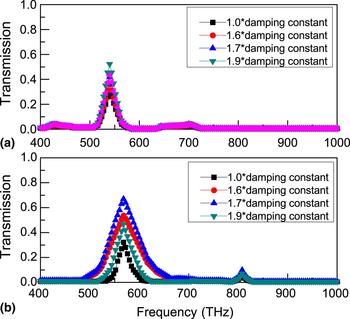
Zhang et al.[ Reference Zhang, Fan, Malloy, Brueck, Panoiu and Osgood 32 ] indicated that the damping constant of the gold film in simulations is lower than that of the gold layers in real systems, which is due to two factors (the grain boundary effect and the surface scattering effect). Therefore, it is necessary to optimize the damping constant of gold films in simulations to reveal a higher performance metamaterial filter. In the following simulations, different times (1.0, 1.6, 1.7, 1.9 times) of the damping constant of gold films are applied in simulations, and the simulated transmission spectra is shown in Fig. 1. For 1.0 times the damping constant of gold films, two transmission peaks (565 and 808 THz) are obtained, as shown in Fig. 1(b). The main transmission peak reaches 35%. For 1.6 times the damping constant, the main transmission peak is increased to 54%. When the 1.7 times the damping constant is used, a strong resonance with 70% transmission is achieved, as shown in Fig. 1(b). A maximum resonance transmittance is achieved by using 1.7 times the damping constant of gold films in simulations, as shown in Fig. 1(b). For the 1.9 times case, the main transmission peak is reduced to 53%. For the pure holes array structure, a maximum resonance transmittance (52%) is also achieved under 1.7 times the damping constant of gold films in simulations, as shown in Fig. 1(a). These simulated results indicate that the 1.7 times the damping constant of gold films is the optimization metal parameter for the proposed structure in this paper, which will be applied in all of the following simulations.
(a) Simulated transmission spectra of the pure holes array structure. (b) Simulated transmission spectra of the proposed structure with different times of damping constants (R = 120 nm, V = 2230 nm).

Simulation results and discussion
Physical mechanism
Electric field distributions of both the main peaks in Figs. 1(a) and 1(b) are calculated, as shown in online Supplementary Fig. S2. For the proposed structure, the resonance of LSP modes are found near the edges of the metal hole at 565 THz, as shown in online Supplementary Fig. S2(a). The coupled electric fields between LSP modes cannot be found. The resonance of LSP modes near the edges of the metal hole results in the main peak of the proposed structure in Fig. 1(b). For the pure holes array structure, the resonance of LSP modes is also found near the edges of the metal hole at 547 THz, as shown in online Supplementary Fig. S2(b). The coupled electric fields between LSP modes also cannot be found. To achieve a better insight into the resonance strength of LSP modes, the calculated electric field (|E|) distributions of main transmission peaks (the proposed structure at 565 THz and the pure holes array structure at 547 THz) are investigated. Two points “A” and “B” near the edges of the hole array are selected as two electric field resonance strength testing points, as shown in online Supplementary Fig. S2. The electric field resonance strengths are named as “|E A|,” “|E B|,” “|E A0|,” and “|E B0|.” In this paper, the electric field enhancement factor is defined as:
 $$\eta = \left \vert E \right \vert /\left \vert {E_0} \right \vert, $$
 $$\eta _{\rm A} = \left \vert {E_{\rm A}} \right \vert /\left \vert {E_{{\rm A0}}} \right \vert, $$
 $$\eta _{\rm B} = \left \vert {E_{\rm B}} \right \vert /\left \vert {E_{{\rm B0}}} \right \vert. $$
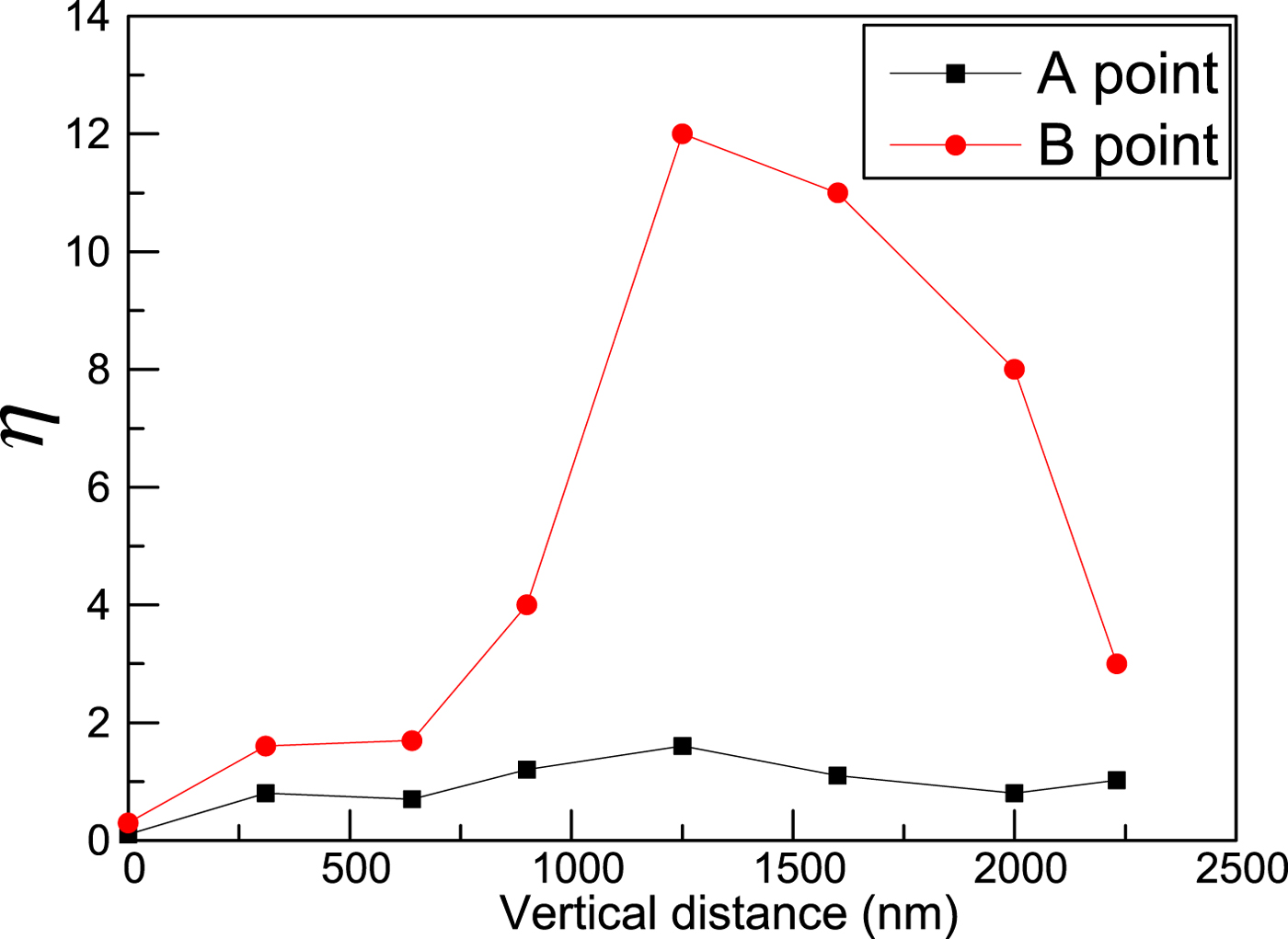
In this paper, the designed metamaterial filter is constituted by a holes array and a metal particle array. To reveal the electric field resonance strength change due to combining the metal particle array and the holes array in a unit cell, the electric field enhancement factor is applied. The electric field resonance strength ratios of the main peak are η A = 1.02 (at the A point) and η B = 3 (at the B point) in Fig. 2, respectively. The maximum electric field resonance strength of the pure holes array structure is lower than that of the proposed structure.
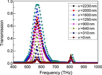
Simulated transmission spectrum of the proposed structure with a different vertical distance of the gold particle (R = 120 nm), 1.7 times the damping constant.

Vertical distance (V) optimization
The simulated results in Fig. 1 indicate that the proposed metamaterial filter obtains a higher main peak than that of the pure holes array structure under the condition using 1.7 times the damping constant of gold films. To achieve a higher performance metamaterial filter, the vertical distance and radius of the gold particle are optimized, respectively. The first set of simulation is carried out with the vertical distance reducing (other structural parameters unchanged). The calculated transmission spectrum is shown in Fig. 2. It is found that the main peak of the proposed structure is increased with the vertical distance reducing. When V = 1250 nm, the transmission enhancement effect reaches a maximum value, and a perfect transmission band near to 100% is achieved. However, when V < 1250 nm, the main transmission peak of the proposed structure is reduced. When V = 0 nm, the metal particle and the bottom metal plate in the same level, the main transmission peak is reduced to 12%.
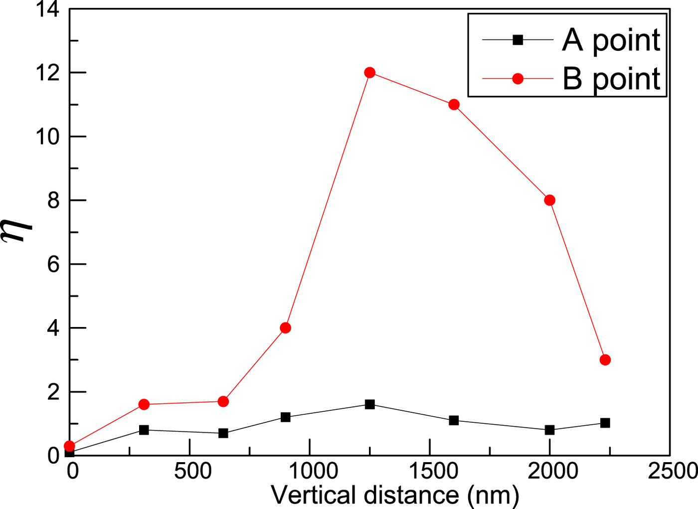
To reveal the relationship between the vertical distance of the gold particle and the transmission spectrum in Fig. 2, corresponding electric field distributions are calculated, as shown in online Supplementary Fig. S3. When the vertical distance is reduced, the LSP modes’ resonance strength near the edges of the holes array is enhanced obviously, as shown in online Supplementary Figs. S3(a)–S3(c). Moreover, the coupling effect between LSP modes and the gold particle is found. When V = 1250 nm, the LSP modes’ electric field strength are enhanced to a maximum value, which leads to the transmission band in Fig. 2. The higher coupling effect between LSP modes and the gold particle is also achieved. While for V < 1250 nm, the LSP modes’ resonance strength is reduced obviously, which results in the reduction of the main peak in Fig. 2, as shown in online Supplementary Figs. S3(e)–S3(h). These simulated results indicate that the resonant field enhancement of LSP modes plays an important role in achieving a high performance of metamaterial filter. Since the resonant field enhancement of LSP modes takes place near the holes array, the electric field magnitude at the A and B points is monitored with different vertical distances. The field enhancement ratio at the A and B points is shown in Fig. 3. It is found that the field enhancement ratio is increased firstly with the vertical distance reducing, and then reached a maximum value when V = 1250 nm. When V < 1250 nm, the field enhancement ratio at the A and B points is reduced. Comparing the results in Figs. 2, 3, and online Supplementary Fig. S3, it can be found that the resonant field of LSP modes can be enhanced by including the gold particle in the proposed structure.
The field enhancement ratio of the A and B points with different vertical distance of the gold particle (R = 120 nm), 1.7 times the damping constant.
Radius of the gold particle optimization
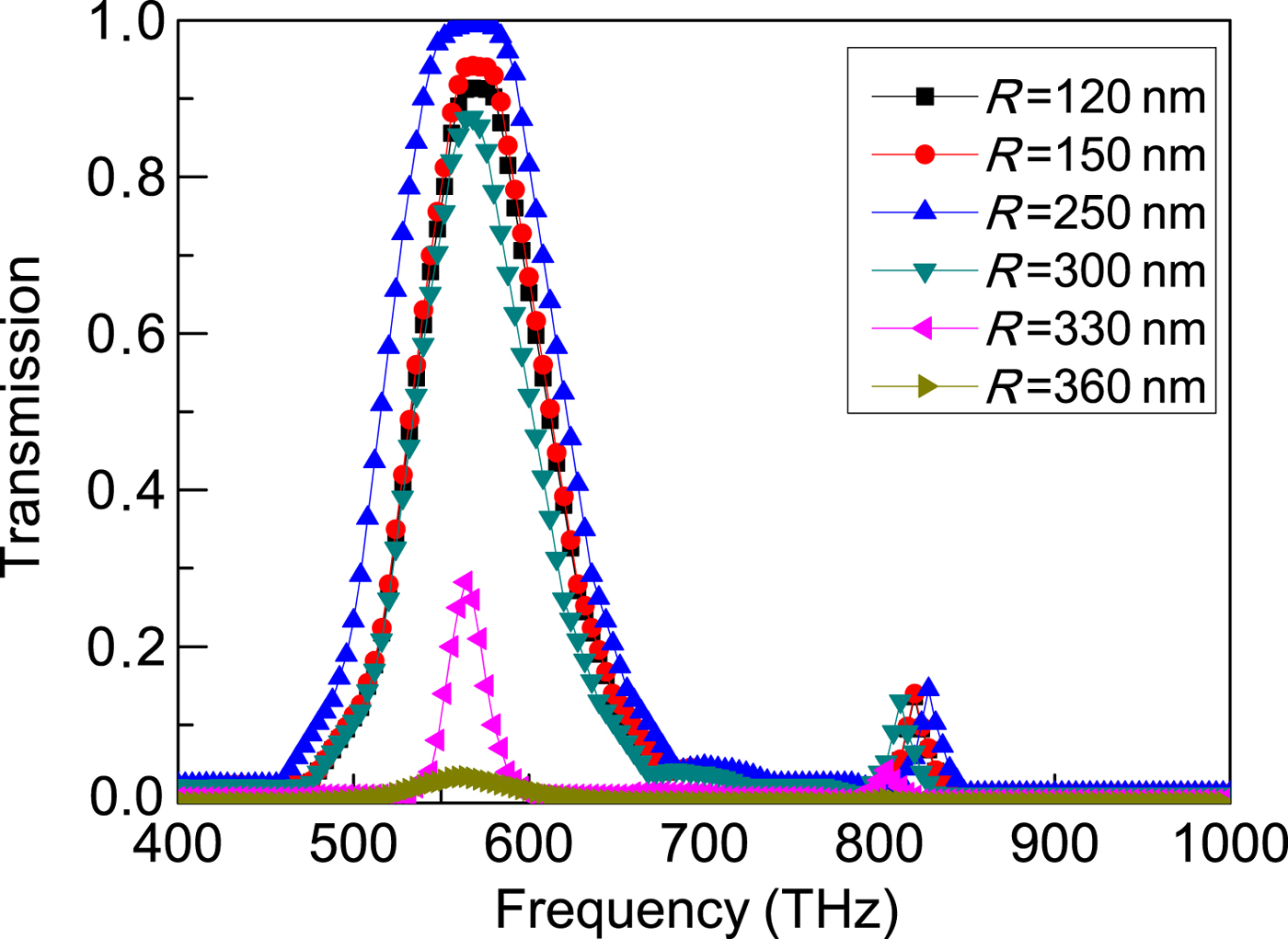
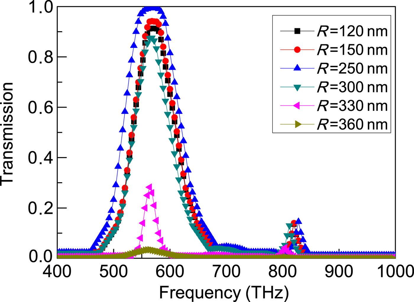
The field enhancement effect on the transmission property is relevantly in the vertical distance of the gold particle, as shown in Figs. 2, 3, and online Supplementary Fig. S3. The effect of the gold particle radius on the field enhancement effect is also needed to be studied. The second set of simulations are carried out with different gold particle radius (under V = 1250 nm, and 1.7 times the damping constant of gold films). The calculated transmission spectrum is shown in Fig. 4. The radius of the gold particle is increased from R = 120 to R = 360 nm. A higher transmission band is obtained (see the red curve in Fig. 4). For R = 250 nm, the transmission is continuously enhanced and a perfect transmission band is obtained, as shown in Fig. 4 (the blue curve). However, the transmission band is disappeared and the transmission peak is reduced when R > 250 nm, as shown in Fig. 4. It is found that the radius of the gold particle also plays an important role in enhancing transmission of the proposed structure.
Simulated transmission spectrum of the proposed structure with a different radius of the gold particle (V = 1250 nm), 1.7 times the damping constant.
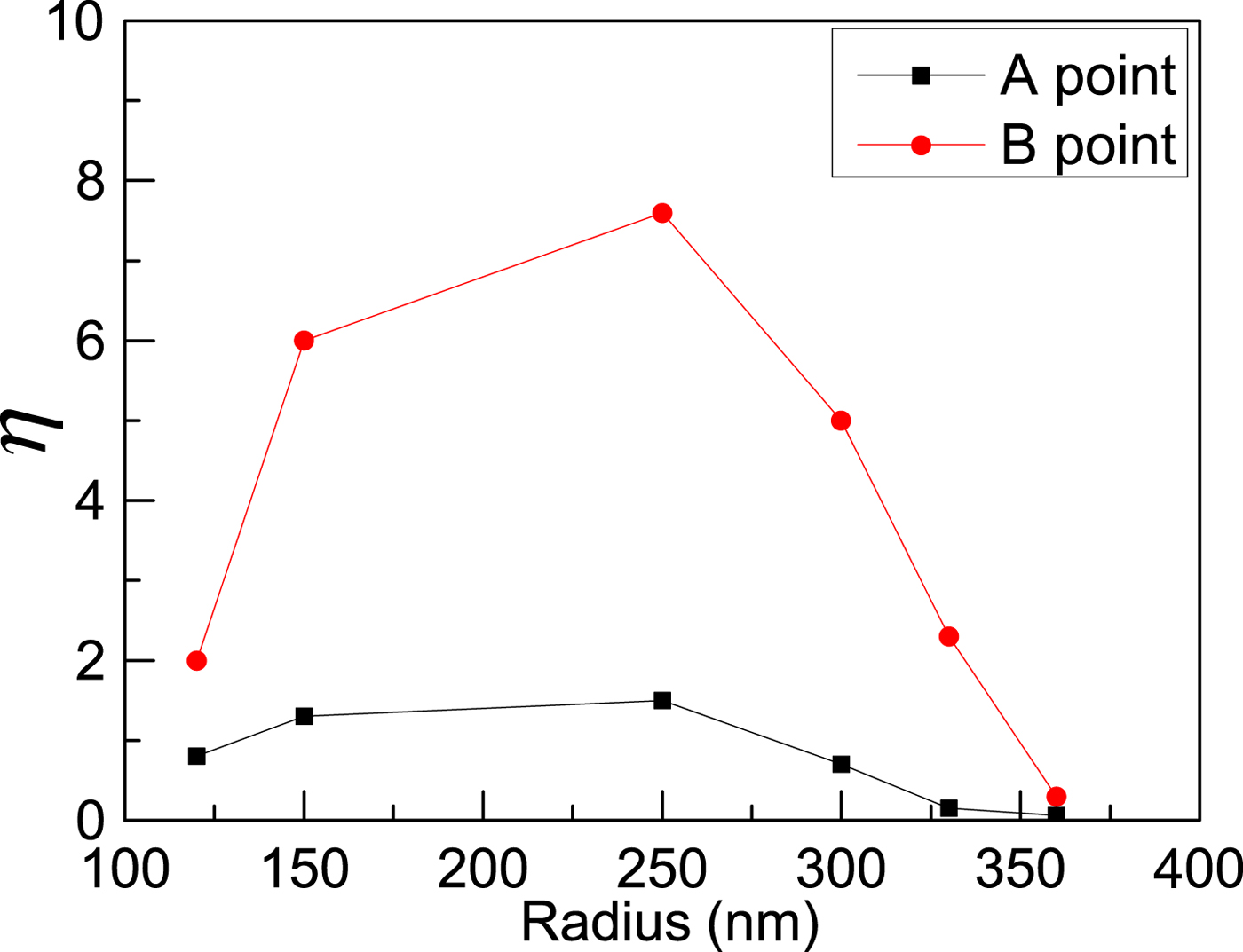
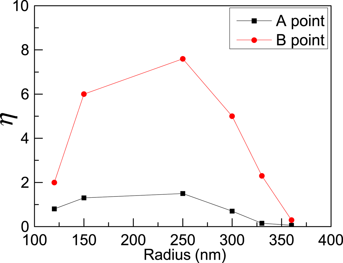
Corresponding electric field distributions relatively to the transmission spectrum are calculated with different radius of the gold particle, as shown in online Supplementary Fig. S4. The resonance intensity of LSP modes near the edges of the hole array is enhanced with R increasing, as shown in online Supplementary Figs. S4(a) and S4(b). When R = 250 nm, the resonance intensity of LSP modes reaches the maximum strength, which results in the maximum transmittance band in Fig. 4, as shown in online Supplementary Fig. S4(c). The strong coupling effect between LSP modes and the gold particle is also achieved, which is similar to that in online Supplementary Fig. S3. When R > 250 nm, the electric field distributions strength is reduced, which leads to the transmittance reduce in Fig. 4, as shown in online Supplementary Figs. S4(d)–S4(f). The electric field magnitude at the A and B points is monitored with different radius, as shown in Fig. 5. It is found that the field enhancement ratio of the A and B points is increased to a maximum value firstly, and then reduced. However, the maximum of the B point is larger than that of the A point obviously. The maximum field enhancement ratio corresponds to the maximum transmission band, which indicates that the transmission of the proposed structure can be enhanced through modulating the field enhancement ratio. The results in Figs. 4, 5, and online Supplementary Fig. S4 indicate that the resonant field of LSP modes can also be enhanced through optimizing the radius of the gold particle.
The field enhancement ratio of the A and B points with a different radius of the gold particle (V = 1250 nm), 1.7 times the damping constant.
Conclusion
In conclusion, an LSP mode resonance metamaterial filter is designed and simulated. The designed structure involves a gold holes array and a gold particle array embedded in the media layer. The damping constant of the simulated metal layers is optimized to eliminate the effects of the grain boundary and surface scattering on the electromagnetic property of the designed metamaterial filter. Simulated results indicate that the transmission can be enhanced through optimizing structural parameters (vertical distance and radius of the gold particle). This electric field enhancement phenomenon is excited by the coupling effect between LSP modes near the edges of holes array and the gold particle. These results suggest that the designed metamaterial filter could be applied in modulating the electromagnetic wave in new types of optoelectronic devices, such as sensor and spectroscopy.
Supplementary material
The supplementary material for this article can be found at https://doi.org/10.1557/mrc.2018.25
Acknowledgments
The project was supported by the National Natural Science Foundation of China (Grant No. 21644013 and 11547196), Key Laboratory of Higher Education of Sichuan Province for Enterprise Informatization and Internet of Things (Grant No. 2017WZJ02 and 2017WYY03), and the key plan projects of Sichuan science and technology department (Grant No. 2016KZ0049). The authors thank the High Performance Computing Center of Sichuan University of Science and Engineering providing simulation calculation support.