
I. INTRODUCTION
The adhesivity of a coating onto a substrate is either by chemical bonding or mechanical bonding,Reference Destefani1 and the adhesivity between a physical vapor deposition (PVD) coating and a substrate is a physical adhesion due to the low deposition temperature.Reference Chen, Wang, Zhou, Li and Zhang2 During arc evaporation, the bombardment of energetic metal ions may cause them to penetrate into the substrate at angstrom levels and knock out some atoms, thus promoting the adhesivity of the coating onto the substrate.Reference Suresha, Bhide, Jayaram and Biswas3 Nevertheless, researchers have increased the adhesivity of PVD-TiCN coatings by introducing a thin interlayer film between the coating and the substrate.Reference Chen, Wang, Zhou, Li and Zhang2
Over the past few decades, titanium nitride (TiN), which is a popular, gold-colored coating, has been applied on high-speed steel and carbide cutting tools.Reference Navinšek, Panjan and Milošev4 The TiN coating improves wear resistance and prolongs the life of high-speed steel and carbide cutting tools, particularly at a high cutting speed and feed rate. The inclusion of carbon atoms into the TiN lattice has improved the tribological properties of the coating. Compared to TiN, titanium carbonitride (TiCN) has a higher chemical stability, more superior mechanical properties and excellent wear resistance.Reference Cheng, Browne, Heckerman and Meletis5 Researchers have suggested that the properties of TiCN can be tailored by controlling its composition through the C–N ratio via several fabrication methods.Reference Cheng, Browne, Heckerman and Meletis5,Reference Bull, Bhat and Staia6
During the machining process, the coating on the cutting tool was delaminated before exposing the tool material, thus acting as a protective film against tool wear.Reference Liew and Ding7,Reference Yigit, Celik, Findik and Koksal8 A coating with higher adhesive strength is thus able to withstand the machining process for a longer time and prolong the tool life. In this paper, the influence of the carbon content within TiCxN1−x coatings with regard to their adhesive strength onto carbide substrates was studied. Both the TiCxN1−x coatings and carbide substrates were custom-made in-house, and the adhesive strength of the in-house custom-made TiCxN1−x coatings was then compared to that of commercially available TiCxN1−x coatings.
II. METHODOLOGY
8 coatings were tested, 6 of them being in-house custom-made TiCxN1−x coatings which were prepared through the cathodic arc physical vapor deposition (CAPVD) method, while 2 were commercially available TiN and TiCN coatings.
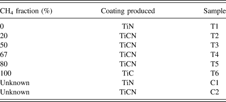
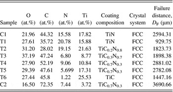
The in-house custom-made substrates comprised of 14 mm × 14 mm × 3 mm WC–6Co tungsten carbides, which were prepared through a powder metallurgy process. The substrates were cleaned ultrasonically in isopropanol for 15 min prior to the CAPVD process. The coatings were deposited onto the substrates via the CAPVD process for 2 h. A titanium (Ti) target with 99.9% purity was used as a cathode and source for Ti, while methane (CH4) and nitrogen (N2) gases were the sources for C and N, respectively. Throughout the CAPVD process, the arc current was kept constant at 100 A, while the reactor temperature was maintained at 300 °C. The CH4 (CH4/(CH4 + N2)) fractions and in-house custom-made coatings that were produced are summarized in Table I. The preparation of the tungsten carbide substrates and the deposition of TiCxN1−x coatings followed the same process as in the previous study.Reference Siow, Ghani, Talib, Ghazali, Selamat and Che Haron9 The adhesive strength of the in-house custom-made TiCxN1−x coatings was compared with that of the commercial TiN–coated (C1) and TiCN–coated (C2) tungsten carbide cutting inserts. All the commercial coatings were also produced by the PVD process and were obtained from Sumitomo Electric (Osaka, Japan).
Deposition of custom-made TiCxN1−x coatings with different CH4 fractions.

The composition, stoichiometry, and intensity of the elements within a coating are made up the functions of the CH4 fraction. These functions were characterized by using the Bruker-D8 x-ray diffractometer (XRD; Karlsruhe, Germany) and the Omicron DAR 400 x-ray photoelectron spectrometer (XPS; Scienta Omicron GmbH, Taunusstein, Germany). The source for the XRD was the Cu Kα with a wave length of 0.15406 nm, while the source for the XPS was Al Kα with 1486.7 eV and a wave length of 0.83386 nm.
The adhesive strength of the coating to the substrate was measured by a micro scratch test, and all the scratch tests were performed using the Micro Materials Nano Test™. A spherical diamond indenter with a radius of 5 µm was used to produce scratches on the sample at a constant speed of 50 µm/s with a progressive loading rate of 16.67 mN/s. The maximum load on this equipment was 500 mN, hence the progressive loading stopped increasing once the maximum load was reached, which was after 30 s and 1500 µm of scratching length. However, some of the coatings did not fail/fracture at this point, and thus, the scratch tests were continued at a constant scratching speed of 50 µm/s and 500 mN of loading until a total of 5000 µm (5 mm) of scratching length was achieved.
A topography scan was run before and after the scratch test at a constant speed of 50 µm/s and a load of 0.2 mN. The coating adhesion failure was indicated by a sudden and drastic change in the (i) topography depth, (ii) acoustic emission, and (iii) dramatic oscillation of the coefficient of friction.10 The adhesion strength in this study was described in terms of the failure distance (D F) (µm), and was determined by the average values obtained from criteria (i), (ii), and (iii) mentioned above.
The effects of the coating adhesivity on the tool wear and thus, the tool life, were studied during the dry turning of AISI 347 stainless steel. The machining was carried out using custom-made tungsten carbide cutting insert, T4 and the commercial cutting insert, C2 at a cutting speed of 300 m/min, 0.10 mm depth of cut, and 0.10 mm/rev of feed rate. The machining test was stopped when the flank wear of the cutting insert exceeded 0.30 mm. The geometry of all the cutting inserts in the machining tests was according to SPUN 120308, whereas the substrates for all the custom-made cutting inserts were prepared accordingly by grinding and polishing before the CAPVD process.
III. RESULTS AND DISCUSSION
A. Influence of carbon content of TiCxN1−x coating on adhesivity
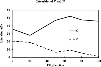
The types of bonds and the intensities of the elements within the thin films were examined using XPS. The XPS results showed the existence of Ti–N, Ti–C, Ti–C–N, Ti–O, C–N, and C–N–H bonds in the examined coatings. In all the examined coatings, most of the N atoms were bonded to the Ti atoms, while most of the C atoms formed adventitious C–C bonds, with only some of the C atoms being bonded to the Ti and N atoms to form Ti–C, C–N, and Ti–C–N bonds. Generally, with an increase in the CH4 fraction, the intensity of the N atoms decreased while that of the C atoms increased (Fig. 1). Hence, the Ti–N bonds were decreased while the Ti–C, C–N, and Ti–C–N bonds were increased with an increase in the CH4 fraction.
Increase in C atoms and decrease in N atoms with increase in CH4 fraction.

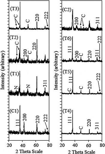
All the tested coatings displayed preferential growth along the plane [111]. Amorphous carbon was detected in all the TiCN and TiC coatings, while amorphous nitrogen was detected in T1 (Fig. 2). The XRD results revealed that T1 to be face-centered cubic (FCC) TiN, T2 to be FCC TiC0.2N0.8, T3 to be FCC TiC0.3N0.7, T4 to be FCC TiC0.7N0.3, T5 to be FCC TiC0.7N0.3, and T6 to be FCC TiC. On the other hand, C1 was FCC TiN, while C2 was FCC TiC0.7N0.3. The XRD results showed that the intensity of the amorphous carbon peaks was increased with an increase in the CH4 fraction.
Comparison of the XRD profile of tested coatings.

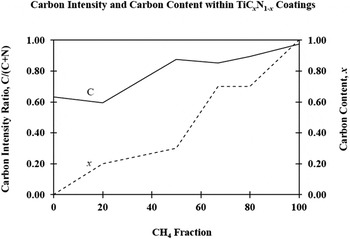
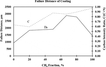
Figure 3 shows the comparison of the carbon intensity and carbon content within a coating. More C atoms were incorporated into the coating than was needed to form TiCxN1−x because the carbon intensity ratio (solid line) was always higher than the x value (carbon content) (dashed line), except for TiC. This demonstrated that the incorporation probability of the C atoms was higher than that of the N atoms, which corresponded to a higher sticking coefficient for the C atoms than for the N atoms due to a more efficient desorption of nitrogen from the film surface.Reference Karlsson, Hultman, Johansson, Sundgren and Ljungcrantz11 In other words, carbon has a higher degree of incorporation into the TiCxN1−x coating than nitrogen. The free carbons that were incorporated in the coating would then form amorphous carbon, as indicated by the amorphous carbon peaks in the XRD spectra.
Carbon intensity ratio and carbon content (x) within TiCxN1−x coating.

However, the incorporation of C atoms into T4 was higher than into T5 and T6 (Fig. 1). This showed that other than the CH4 fraction and the sticking coefficient of the C atoms, there must have been other factors that affected the incorporation of the C atoms into the coating. These factors could be the ionization efficiency (deposition efficiency) and the efficiency of forming Ti–N, C–N, Ti–C, and Ti–C–N bonds. The ionization efficiency was mainly affected by the arc current (energy provided),Reference Lugscheider, Barimani, Wolff, Guerreiro and Doepper12 which was kept constant at 100 A throughout the CAPVD process. Thus, the ionization efficiency in this study was roughly constant. The ionization efficiency reached an optimum “reaction state” with respect to the gas fraction (volume) that was channeled into the reactor chamber. Any further increase in the gas fraction (volume) will not increase the ionization efficiency, but instead may incur defects. In this study, the optimum ionization efficiency was achieved when the CH4 fraction was 67% because T4 had lower amorphous carbon peaks with higher intensity of the C atoms.
Another factor that affected the incorporation of the C atoms was the bonding efficiency. The materials in the TiN–Ti(C,N)–TiC series are a mixture of covalent metallic and ionic bonding. As the N atoms were replaced by C atoms, the degree of covalent bonding increased and the occupation of the antibonding state was decreased, because the C atom has one valence electron less than nitrogen.Reference Karlsson, Hultman and Sundgren13 Therefore, more C atoms were incorporated into the coating to achieve equilibrium and a stable chemical state.
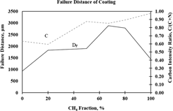
Table II shows the scratch test results and a summary of the XRD and XPS analyses, and thus the effect of the coating composition on the adhesion failure. In the custom-made coatings, the TiCN coatings (T2‒T5) had the highest adhesivity, followed by the TiC (T6) and TiN (T1) coatings, whereas C2 also showed a higher adhesivity to the carbide substrate than C1.
Element intensity, coating composition, and adhesion failure.

In general, the adhesivity of the custom-made TiCN coatings increased with an increase in the carbon content (CH4 fraction) (Fig. 4). This showed that the carbon content within the TiCN coatings promoted adhesive strength. However, since T6 (TiC) had a lower adhesivity than T2 (TiCN) despite its higher carbon intensity, thus there must have been a factor that had a greater effect on the adhesive strength, rather than just the intensity of the C or N atoms. The better adhesive strength of T2 compared to T6 showed that it was the Ti–C–N and C–N bonds, and the C/N ratio (x value) within the TiCxN1−x coating that significantly improved the adhesive strength rather than the C or N atoms. Therefore, the C/N ratio, and the Ti–C–N and C–N bonds had a greater influence on the adhesive strength compared to the carbon intensity (content). The C/N ratio should be taken into account before the carbon intensity in the determination of the adhesive strength of a TiCxN1−x coating. For the TiCN coatings, the coating with the higher carbon intensity had better adhesivity to the carbide substrate. Nevertheless, it is never wrong to say that the adhesive strength of the TiCxN1−x coating increases with the carbon intensity.
Failure distance (D F) of coating.

In addition, several researchers have reported that TiCN is a solid solution of the FCC TiN and FCC TiC,Reference Yang, Yao and Zhang14,Reference Bemporad, Pecchio, De Rossi and Carassiti15 which takes on the excellent characteristics of both TiC and TiN. Moreover, the TiCN and TiC coatings have a greater propensity to develop brittle eta phase at the coating-substrate interface, which is beneficial to the adhesivity of the coating.Reference Narasimhan, Boppana and Bhat16 Thus, the TiCN coating can further improve the adhesive strength of the coating.
B. Performance of cutting insert on machining of AISI 347
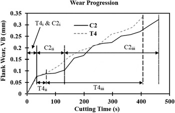
Figure 5 shows the wear progression of T4 and C2 in the dry turning of AISI 347 stainless steel. It can be clearly seen that the wear progression of the cutting insert can be divided into 3 stages, (i) initial and rapid wear, (ii) gradual and uniform wear, and (iii) accelerating wear leading to tool failure.Reference Khrais and Lin17,Reference Noordin, Venkatesh and Sharif18 In this study, the initial and rapid wear only occurred for the first run and took place for about 30 s. After that, the tool wear was uniform and gradually developed on the cutting inserts. Finally, the tool wear was accelerated until it reached its full life.
Wear progression of T4 and C2 in dry turning of AISI 347.

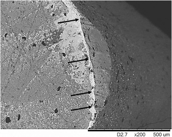
It was found that the tool wear was dominated by abrasion wear, where grooves were formed on the surface of the cutting insert (Fig. 6). During the machining, the cutting tool was always rubbing against the workpiece material. Even though the cutting insert was harder than the workpiece, the workpiece material still ploughed into the tool and plucked out the carbide particles, leading to a weaker tool surface strength and resulting in the formation of grooves.Reference Attanasio, Umbrello, Cappellini, Rotella and M'Saoubi19 Furthermore, AISI 347 stainless steel is an abrasive material, and this increased the severity of the formation of abrasion grooves.Reference Deng, Zhou, Zhang and Yan20
Formation of abrasion groove on cutting insert.

In the wear progression, the coating was delaminated before the exposure of the carbide substrate and led to a more aggressive and accelerated tool wear.Reference Liew and Ding7,Reference Yigit, Celik, Findik and Koksal8 Thus, the coating acted as a protective layer against tool wear. The adhesive strength of the coating then determined the duration of stages (i) and (ii). The duration of stage (ii) for T4 and C2 was denoted by T4ii and C2ii in Fig. 5, and the coating with the higher adhesive strength then promoted a longer tool life.
IV. CONCLUSION
The TiCN coating had the best adhesive strength on a tungsten carbide substrate, followed by the TiC coating and lastly, the TiN coating. The adhesive strength of the TiCxN1−x coatings onto a tungsten carbide substrate was increased with an increase in the C/N ratio (x value) and the carbon intensity within the coatings. The C/N ratio, C–N, and Ti–C–N bonds within a coating had a greater effect on the adhesive strength of the coating rather than the C or N content.
In this study, the tool wear was dominated by abrasion wear. The coating was delaminated before the exposure of the carbide substrate and led to acceleration in the tool wear. The higher adhesive strength of the coating then promoted a longer tool life.
ACKNOWLEDGMENTS
Part of this paper was originally accepted for and presented at the MITC 2015. The authors would like to thank the government of Malaysia, Universiti Kebangsaan Malaysia, and Advanced Materials Research Center, SIRIM Berhad, for their support in terms of finances, manpower, and facilities.