Introduction
There is a pressing need to use renewable energy (solar, wind, geothermal) as well as to provide efficient storage and supply of mobile energy to enable the application of consumer electronics batteries to longer-range commuter electric vehicles. In the energy-storage sector, electrochemical energy storage based on the reversible conversion of chemical energy and electrical energy, both having a common carrier (i.e., electrons), has dominated for over two centuries. Li-ion batteries, which were commercialized by Sony in 1991, have far outperformed other technologies in terms of energy density with adequate rate capability, longevity, and large-scale commercial applications. Thus, Li-ion batteries hold the promise and burden to sustain our energy-demanding society.
For illustrating the path toward rechargeable batteries with ultimate sustainability, we first spotlight the principle of present Li-ion battery systems (see the Introductory article in this issue). As illustrated in Figure 1, there are three main components: a positive electrode (also termed as cathode), a negative electrode (anode), and an electrolyte. Such batteries have employed low-voltage carbonaceous materials without Li as anodes and LiCoO2 as cathodes acting as a source of Li. This kind of Li-ion battery possesses a working voltage exceeding 3.6 V and gravimetric energy densities between 120 and 150 Wh/kg, which is two or three times that of typical Ni-Cd batteries. During the charge process, the chemical reactions occurring at both electrodes can be expressed as follows:
 $$(Cathode) LiCo{O_2} \to \,L{i_{1 - x}}Co{O_2} + xL{i^ + } + x{e^ - }$$
 $$(Anode)\,{C_6} + xL{i^ + } + x{e^ - } \to L{i_x}{C_6}.$$
Concept of future rechargeable batteries with more abundant elements toward sustainable grid storage. In a lithium-ion battery, Li ions can insert into both electrodes, which act as hosts; this mechanism is known as intercalation. The role of liquid electrolytes, which always consists of a solution of a lithium salt dissolved in an inert solvent, is to act as an ionic conductor to transport lithium ions back and forth between the two electrodes as the batteries are repeatedly charged and discharged.

During the discharge process, the reactions proceed in the reverse direction. In the following sections, achievements and problems in elemental strategy will be discussed toward (simultaneous) replacing Co with Fe and Li with Na.
Why Fe in rechargeable batteries?
Building batteries is a multifaceted engineering riddle that attempts to garner maximum energy/power density without compromising cost and safety. As a lightweight center of reversible redox reaction in the cathode material, 3d transition metals (Mn, Fe, Co, Ni) offer higher electronegativity using electrons that bind more strongly to the nuclear charge, whereby they are preferable because they can generate higher voltage to gain energy density. Mn, Co, and Ni have been the dominant elements in cathode materials in the form of LixMO2 (M = Co, Ni) and LixMn2O4 for commercial batteries until recently.1,2 However, keeping an eye on natural abundance (see Table I) and material cost, Fe is gaining ground. Being the fourth most abundant element widely distributed in the earth’s crust, Fe will have less impact on the environment and low toxicity. Such attractive features inherent to Fe are particularly important for large-scale applications, particularly the strong social demand for vehicle and grid applications. This has led materials scientists to devote tremendous efforts to utilize the reversible redox reaction of Fe in the solid matrix form.
Elements with a large Clarke number.
Based on information from Reference 42.
Li-battery cathode: Road to olivine LiFePO4
The most efficient chemical composition of the cathode material can be denoted as LixM4+/3+O2 (0 < x < 1), where all of the lithium ions and electrons can contribute to a one molar electrode reaction in the condensed solid matrix through various close-packed oxygen arrays. In practical use, however, the lithium composition is limited to ca. 0.5 < x < 1 to avoid structural instability and safety risks due to oxygen evolution.3 A simple expansion of this design to LixFeO2 has led to unimpressive battery performance, regardless of its polymorphic variations. In the ceramics literature, it is common to characterize structural stability on the basis of size and charge effects. The Pauling rules, useful in predicting the structure of many simple oxides, are examples of this. In ABO2-type compounds (A, B = cations), the α-NaFeO2 structure (isostructure with LiCoO2 and LiNiO2) is stabilized as the size difference between cations is increased and the charge on the B cation is reduced. Unfortunately, LixFeO2 is unstable because the ratio of ionic radii r Fe3+/r Li+ = 0.88 (0.77–0.78 for LiCoO2 and LiNiO2) does not satisfy the semiempirical tolerance criterion, r B/r A < 0.86, for the layer structure.4
In order to overcome these difficulties, a series of compounds, including large polyanions (XO4)y– (X = S, P, As, Mo, W, y = 2 or 3), were explored, and the use of (PO4)3– and (SO4)2– has been shown to stabilize the structure and lower the Fe3+/Fe2+ redox energy to useful levels. The presence of strong X–O covalency stabilizes the antibonding Fe3+/Fe2+ state through an Fe-O-X inductive effect to generate an appropriately high voltage around 2.8–3.6 V versus lithium.5
Based on schematic energy diagrams for some phosphates and sulfides (see Reference 3), LiFePO4 satisfied almost all criteria for use in a practical Li-ion battery:3,6 (1) ablility to function as a lithium source upon oxidation from Fe2+ to Fe3+, (2) high operation voltage at 3.45 V, (3) full utilization of a large theoretical capacity of 170 mAh/g, (4) reasonable true density of 3.6 g/cc with a hexagonal oxygen close-packed array, (5) volume shrinkage (ca. 7%) upon charge process, compensating for the simultaneous expansion of the carbon-based negative electrode in a cell, (6) mixed polaronic/ionic conduction by its crystallographic nature, and, most importantly, and (7) extremely safe, with thermal stability over 700°C. The term “utilization” in (3) is very important, as the practical capacity in a battery does not show any correlation to the theoretical capacity, and low utilization means a larger number of “dead” atoms in the compound, as illustrated in gray areas in Figure 2. Two major drawbacks of LiFePO4 were recognized as easily blocked one-dimensional lithium diffusion7–10 and low electronic conductivity in slow hopping sequence,11 but these were successfully overcome, as shown in the ideal charge-discharge curves realized by particle downsizing and carbon coating (Figure 3).3,11–13 After 2006, high-rate Li-ion batteries with a LiFePO4 cathode became commercially available and are widely used for power tools and larger scale applications.
Capacity utilization (practical capacity versus theoretical ones) of various iron-based cathode materials for lithium-ion batteries. For comparison, those for LiCoO2 and LiMn2O4 are also included. The practical capacity in a battery does not show any correlation to the theoretical capacity.
(a) Crystal structure of LiFePO4 with a visualized one-dimensional lithium diffusion path in green. The brown octahedra represent FeO6, and the purple tetrahedra represent PO4 units.9 (b) Typical charge-discharge (voltage versus stored charge) curves of LiFePO4 (first three cycles). Very flat voltage profile at 3.45 V with large capacity close to the theoretical value (170 mAh/g) is suitable as a cathode material. PC/DMC (propylene carbonate/dimethyl carbonate) 1 M LiPF6 is the electrolyte composition; 1 mol/l of LiPF6 is dissolved into a 1:1 solution of PC to DMC.3
Where is the ultimate limit of Fe redox function?
Inspired by the success of LiFePO4, several compounds were explored to further utilize the redox reaction of Fe more efficiently toward higher energy per weight/volume. Major directions were (1) increasing the number of redox electrons per transition metal, (2) minimizing the weight and volume of the host framework, and (3) raising the redox potential.
Exploration for >1e– reaction
In order to overcome the capacity limit by the one-electron Fe3+/Fe2+ redox reaction, several compounds with the ratio Li/Fe = 2 were explored, including Li2–xFeSiO4 (2.8 V),14 Li2–xFePO4F (3.2 V),15 and Li2–xFeP2O7 (3.5 V).16 However, access to tetravalent iron, Fe4+, by removing a second lithium atom from the lattice is very difficult because of the too high Fe4+/Fe3+ potential and/or structural instability upon deep oxidation. Stable reversible reactions were confirmed only for the one electron reaction at 0 < x < 1. A few reports claim reversible two electron reaction in Li2–xFeSiO4 (0 < x < 2)17–19 but with sluggish kinetics, which may be caused by a framework-breaking surface reaction with atomic rearrangement. Such parasitic slow reactions are observed exclusively at very small nanoparticles that do not warrant application to practical electrodes because of a significant sacrificial decrease in volume energy density.
Lightening and compaction of host framework
In comparison to the oxide cathodes, the polyanionic framework compounds invariably suffer from lower theoretical capacity owing to the weight and volume penalty of constituent polyanion units. The metal borate (LiMBO3) family forms a special class of polyanionic cathodes with the lowest-weight polyanions (BO3)3− with a molecular weight of 58.8, which is significantly lighter than the larger tetrahedral (PO4)3− unit with a molecular weight of 95.0. A large theoretical capacity of 220 mAh/g is calculated based on the LiFeBO3 chemical formula, which is much larger than the 170 mAh/g for LiFePO4.Furthermore, the true density of LiFeBO3 is 3.46 g/cm3, which is close to that of LiFePO4 and suitable for maximizing the volume energy density due to the minimum volume occupation of the planar triangle BO3 oxyanion unit.20,21 Carefully prepared LixFeBO3 shows room temperature activity as a cathode with a capacity of >190 mAh/g at around 3 V versus Li (Figure 4).20,21 A significant positive impact is realized by avoiding surface poisoning due to contact with the ambient atmosphere. However, the voltage window of 1.5–4.5 V to cover large polarization is too large for practical applications. Moisture sensitivity is another important factor that needs to be investigated before its application in commercial products can be considered. Once these problems are solved, borates, rather than heavier and larger phosphates, could be a new avenue for the exploration of novel electrode materials.
Experimental and calculated open-circuit voltage of LixFeBO3; average open-circuit voltages were calculated between the lowest energy intermediate phases demonstrated by the red line. Reprinted with permission from Reference 20. © 2010 Wiley.
Raising the Fe3+/Fe2+ redox potential
The cell voltages with M = Fe show the trend LiFeBO3 < Li2FeSiO4 < LiFePO4F < LiFePO4 < Li2FeP2O7 < LiFeSO4F.22,23 This trend (see Figure 5) roughly follows the formal charges of the central atoms in the polyanions, which is consistent with the idea of the inductive effect. More essentially, the voltage is defined as the difference between the lithium chemical potential in the cathode and in the anode, leading to the simple thermodynamic definition ignoring PV and TS terms (P = pressure, V = volume, T = temperature, and S = entropy),
 $$E = ({G_{Li}} + {G_{charged}} - {G_{discharged}})/nF.$$
A historical diagram comparing the potential of Fe3+/Fe2+ redox couple versus lithium of various Fe-based cathode materials. “Phen” is the abbreviation of phenanthroline. Reprinted with permission from Reference 27. © 2012 Wiley.
where G Li, G charged, and G discharged are the Gibbs free energies of Li metal, charged cathode, and discharged cathode, respectively, n is the number of electrons to the redox reaction, and F is the Faraday constant. A shorter Fe3+–Fe3+ distance in the charged state is effective for enlarging G charged, and hence the operating voltage E, while the influence of the discharged state G discharged with smaller charge Fe2+ can be subordinated in energetics.24 Of particular interest is the triplite phase of LiFeSO4F and metal doped Li2FeP2O7, which possess edge sharing FeO6 octahedra to minimize the Fe-Fe distance, as distinguished from other lower voltage Fe-based polyanion cathodes with corner-sharing octahedra. The cell voltage for these two materials can reach as high as 3.9 V (versus Li), which is higher than the value of 3.8 V calculated from the standard redox potentials. The latter has been suggested to be the highest achievable voltage for a Li-ion battery utilizing the Fe3+/Fe2+ redox couple in a solid.25,26
A historical overview of the Fe3+/Fe2+ redox potential is summarized in Figure 5, in which an inspiring feature is that now the most commonly accessible redox Fe3+/Fe2+ can, in principle, generate a high voltage value of 3.9 V versus lithium (and hence 3.6 V versus sodium).27 In spite of the larger G charged, this can be realized without sacrificing the thermal stability (safety margin)28 and is suitable to maximize energy density under the constraint of the electrolyte stability window.
Li versus Na: Similarities and differences
There has been a resurgence of interest recently in sodium (Na)-ion batteries (see the Kubota et al. article in this issue). Enlightened by the rich experience with compound structures in Li-ion batteries, new cathode materials based on layered oxides and polyanions have been continuously discovered. The main factors affecting the applicability of a cathode such as voltage, conductivity (electronic and ionic), and stability are being addressed. One notes that all of these factors are determined by the phase behavior of the material in different states of charge. A Na+ ion is much bigger than a Li+ ion (102 pm versus 76 pm), and intercalation of Na+ into typical hosts for Li+ ions may result in different phase behavior. Therefore, elucidation of the phase diagram will provide an essential basis for understanding the material performance.
As a typical example, NaxFePO4 and LixFePO4 show completely different phase diagrams.29 The volume expansion of FePO4 upon sodiation (sodium intercalation) to NaFePO4 is large, about 17% (Figure 6). The existence of an intermediate phase at x = 2/3 in the Na case, which is very stable up to 500°C, is somehow anticipated to relax the large lattice strain between the x = 0 and x = 1 phases. However, even with the existence of an intermediate phase at Na2/3FePO4, one notices that the expansion from FePO4 to Na2/3FePO4 is still quite large (12.8%), nearly two times that for LixFePO4 to change from x = 0 to 1 (Figure 6), which may disturb the sustainment of a coherent interface for smooth electrode reaction. Difficulties in direct synthesis, sluggish electrode kinetics, and low voltage around 2.7 V versus Na30 are three major obstacles hindering NaFePO4 from practical application.
Schematic diagram comparing the volume expansion of FePO4 upon lithium and sodium insertion. For LixFePO4, no intermediate structure between 0 < x < 1 is found. For NaxFePO4, an intermediate phase at x = 2/3 exists to “buffer” the large volume expansion. The difference of ionic radii between Li+ and Na+ causes a significant difference in the phase diagram. Reprinted with permission from Reference 29. © 2013 American Chemical Society.
Toward Na-ion battery cathode: The present status
In spite of the great success with olivine LiFePO4, the sodium analogue with the same structure has turned out to be unsuitable for an electrode. Although the switch to Na from Li is the conceptually obvious way to follow, simple extension by just replacing lithium with sodium does not always lead to similar performances, and in many cases ends in failure. Therefore, strategies should be directed toward specific exploration of new materials suitable for the sodium system.
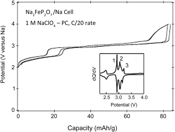
Renewed interest in Na-ion chemistry has seen extensive research on various P2- and O3-type oxide layered compounds (see the Kubota et al. article in this issue) and their solid solutions, mostly based on expensive transition metals such as Co and Ni. Large-scale sodium batteries will be commercially viable with earth-abundant transition metals such as Fe. Different from the lithium case, NaxFeO2 satisfies the tolerance criterion, r B/r A < 0.86, thanks to the larger ionic radius of Na+ (r Na+ = 102 pm, r Li+ = 76 pm). To date, O3-type NaFeO231,32 and P2-type Nax[Fe1/2Mn1/2]O233 have been reported, both suffering from low operating potential even by using a Fe4+/Fe3+ redox couple, and the stable reversible capacity is limited. Using the inductive effect in polyanion framework systems, the Fe3+/Fe2+ redox potential can be enhanced with full utilization of a one-electron reaction. In this pursuit, many ∼3 V Fe-based phosphate PO43– insertion compounds other than the olivine phase have been reported. These include Na2FePO4F (3.06 V),15 Na2FeP2O7 (2.9 V),34 and Na4Fe3(PO4)2(P2O7) (3.2 V).35 Among these, Na2FeP2O7 (Figure 7) shows high current-rate performance and extreme thermal stability. The Sumitomo electric company chose Na2FeP2O7 in parallel with NaCrO2 as cathode materials for their prototype Na-ion battery pack using a molten-salt electrolyte operating around 60–90°C.36,37 However, iron-based high-voltage materials of >3.5 V versus Na have yet to be reported and warrant exploration in the future.
Charge-discharge curves of Na2FeP2O7. (Inset) The dQ/dV curve (derivative of capacity by voltage) of charge-discharge profile showing several distinct peaks. The peak ∼3 V has three distinct steps marked as 1, 2, and 3. Applied current is represented as C/20, meaning full theoretical capacity is reached in 20 hours.34
Summary
At the present stage, Na-ion batteries are not a strong competitor for Li-ion chemistry by only considering sodium’s greater abundance compared to the well-established state-of-the-art Li-ion power packs. However, it has rapidly attracted the attention of many materials scientists. Both weak Lewis acidity and the large polarizability of Na-ion allow fast charge transfer reactions at electrode/electrolyte interfaces and in bulk diffusion.38–40
Furthermore, unlike the incremental progress of the mature Li-ion systems, researchers of the immature Na-ion systems based on Na-ion intercalation are likely to discover new electrodes with ordered functional structures due to the difference in the ionic radius of Na and 3d transition metals, which may enable Na-ion batteries to surpass Li-ion batteries. The abundance of Na should not be compensated for by combination with rare transition metals, thereby Fe is definitely the best to functionalize. Maximizing the redox function of Fe has been intensively studied in the lithium system, from which we can expect to realize >3.6 V operation in the Na system.
However, the present status is still far from this technical target. Operating voltage and reversible capacity of various known iron-based cathodes for Na-“ion” (cathode functions as the whole sodium source) battery systems are summarized in Figure 8. Further effort to reach a primary target of >3.6 V operation and capacity around 125 mAh/g can lead to an energy density >450 Wh/kg, which is comparable to those of LiMn2O4 (430 Wh/kg) and LiFePO4 (500 Wh/kg) in lithium systems.41 Exploration for emerging Na-ion battery electrodes is still at an early stage, and further contributions from materials scientists are welcome.
Overall comparison of the Fe-based cathode materials that can function as sodium sources in a Na-ion battery system. Polyanionic cathode materials are shown as green boxes and simple oxides/fluorides as blue. The yellow band indicates the voltage region, which ensures compatibility with Li-ion batteries. A reasonable target region is illustrated as a dashed red circle. (*The capacity of P2-Na2/3[Fe1/2Mn1/2]O2 is assumed by the inherent amount of sodium, including the Mn4+/Mn3+ redox reaction, as separately denoted with the dashed pale-blue box. Dashed pale green for NaFePO4 indicates it cannot be directly synthesized and has sluggish kinetics in electrode reaction.)
Acknowledgments
Financial support from the Ministry of Education, Culture, Sports, Science and Technology, Japan (MEXT), under the “Element Strategy Initiative for Catalysts & Batteries” (ESICB) project is gratefully acknowledged.