
Introduction
Conventional methods to produce original equipment manufacturer (OEM) parts include formative manufacturing (FM) and subtractive manufacturing (SM). Examples of FM include injection molding, pressing, die casting, and stamping wherein high-quality parts can be produced at a very low cost and high throughput.[1] The downside of FM is the initial high cost as well as the lead time to produce the mold. In SM, wherein parts are produced by removing/subtracting material from larger pieces of material, the cost of the machine and the serial production method are also drawbacks. Examples include computer numerical control (CNC) machining, turning, milling, drilling, etc.[1,2] Although SM is a highly accurate production process, it is considered a wasteful process as it has a high “buy-to-fly ratio”. The buy-to-fly ratio is the ratio of the mass of the starting billet of material to the mass of the finished part.[Reference Kobryn, Ontko, Perkins and Tiley3] Additionally, it is not possible to produce complex geometries using this method.[Reference Le, Paris and Mandil4]
A new and alternative method for tooling and production, which is a direct opposite of SM, is additive manufacturing (AM). AM, or more commonly known as 3D printing, is now being used for rapid design conceptualization. With recent advances in machine design and materials, various 3D printing technologies are now widely available and are being used for OEM production. These developments continuously revolutionize how products are designed, manufactured, and how they can eventually be used.[Reference Dizon, Espera, Chen and Advincula5] Design, redesign, and production of simple and complex parts at a faster phase is now possible. AM is now heavily used in applications like aerospace, automotive, marine, fashion, medicine, dentistry, automotive, electronics, military, construction, food, etc. Revenues from the global 3D printing market were estimated to reach several billion U.S. dollars each year, and a steady growth in spending on equipment, materials, accessories, and software is expected.[Reference Dizon, Espera, Chen and Advincula5]
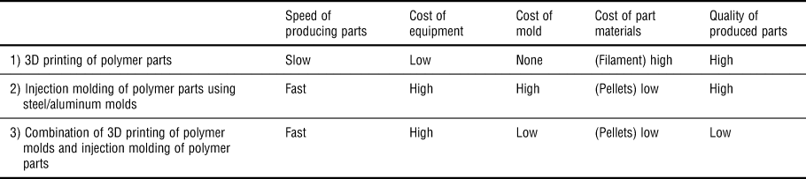
Although 3D printing is a relatively slow process like SM, combining 3D printing (for pattern and mold design) and injection molding (for mass production) will be of high interest especially in reducing the lead time for tooling and mold fabrication. By using 3D-printed polymer molds, the price of producing parts is even expected to be less expensive compared with steel/aluminum molds as summarized in Table I (comparison of the three processes). As demonstrated in the table, the proposed method (i.e., #3) has a faster production time and lower cost of producing the mold. However, the quality of produced parts is still relatively low and is limited to low-production runs. Since very few reports are available regarding this novel combination of manufacturing methods, it is very important to understand 3D-printed mold design and their material requirements. Specifically, the objective can be focused on how to optimize mold design, understand, and improve the quality and processing of 3D-printed molds, and ultimately to better understand the injection molding process with the use of polymer mold materials.[6,7] To demonstrate the challenges, initially, the injection molding process, 3D printing technologies and materials challenges were reviewed. The second part is an actual demonstration of the combination of these technologies and materials with fabricated polylactic acid (PLA) parts and possible pathways to overcome their limitations.
Comparison of three different methods to produce parts.

Review of injection molding
Overview of the injection molding process
Injection molding is one of the most established and well-known methods of plastic processing. It occupies a major part in the plastics industry ranking second to plastic extrusion in terms of production and the utilization of both thermoplastic and thermosetting plastic materials.[Reference Rosato and Rosato8,9] It is capable of producing parts in very large volumes and throughput, especially when continuously producing a similar part in thousands or millions of times.[Reference Khan and Acharya10]
The injection molding process can be divided into four steps: (i) the selection of the product that is going to be produced and the selection of suitable plastic resin[Reference Khan and Acharya10]; (ii) the preparation of the mold, runner, gate, and process parameters such as temperature, pressure, flow rate, and cooling rate[Reference Khan and Acharya10–Reference Rizvi12]; (iii) feeding the plastic material into a barrel with a heating element through the hopper, mixed, forced into the mold cavity by a screw, then the material cools down and solidifies into the shape of the mold cavity.[9–Reference Frizelle11]; and (iv) the removal of the final part from the mold after solidification.[Reference Khan and Acharya10]
Several approaches to efficient injection molding operations have been widely researched and implemented to address the performance requirements in the production of injection-molded plastic parts for various existing markets. In the FALLO approach, Follow ALL Opportunities is one of the implementable approaches for a complete injection molding operation. This approach shows the interdependencies of processes involved in injection molding operations such as the software and hardware operations.[Reference Rosato and Rosato8,Reference Rogers13]
Applications of injection molding
Injection molding has been used for decades in the production of high-volume commercial products such as spools, bottles and caps, vehicle dashboards and other automotive parts, monolithic and multipart chairs and tables, containers, mechanical components, and most plastic-based products that are available at present. Approximately 180,000 various types of materials could be injection-molded back in 1995 and that number continues to rise at a rate of 750 annually.[14]
Injection molding, in general, is not limited to using plastic materials. Metal injection molding (MIM) is a metalizing process using a mixture of binder material and fine metal powder and then shaped via a traditional injection molding process. MIM has been seen to have a potential for supplementing AM technologies, and vice versa,[Reference Johnson15] with the use of furnace sintering technology in building the parts.
Injection molding of polymeric materials in micro- and sub-micron structures and for microfluidics applications has been widely researched as well,[Reference Greener and Weimberg-Freidl16,Reference Liou and Chen17] bringing the advantages of injection molding process into size-scalable applications. The term microinjection molding is popular in the context of injection molding of microscale structures, especially in microfluidics applications.[Reference Greener and Weimberg-Freidl16]
Benefits of injection molding
Plastic injection molding has been considered ideal for high-volume production of plastic parts because the production cycle can be designed using part-specific injection molds.[18] In addition, injection molding is advantageous in terms of “repeatable high tolerances, ability to use a wide range of materials, low labor costs, minimal scrap losses, and little need to finish parts after molding”.[14] The primary advantage is its scalability wherein the unit price extremely drops as more and more of the same parts are produced.[Reference Rogers13] On the other hand, its tradeoffs include “expensive equipment investment, potentially high running costs, and the need to design moldable parts”.[Reference Rogers13,14]
In terms of injection molding operations control system, the process control concerns the following[Reference Agrawal, Pandelidis and Pecht19]:
(i) A multidisciplinary approach of chemical and mechanical engineering, optimization, computer science, and statistics is required, as well as knowledge in fluid flow, mass, energy, and heat transfer processes.
(ii) Sophisticated interdependencies in the above-mentioned variables; the output of each process depends on the previous process in a time-series fashion. Thus, alternatives to the traditional PI and PID controls should be considered.
(iii) A steady-state value may be difficult to achieve due to the dynamic and cyclic nature of the injection molding process. Thus, more advanced controls are needed.
In addition, several downsides of injection molding include the following[Reference Rogers13]:
(a) High tooling costs and large required lead times: Before producing plastic products, engineers need to design a prototype[Reference Malloy20] mold made from CNC or 3D printing. These prototypes then need to be replicated into a mold tool. This entire process takes several iterations and requires cost and longer lead times to achieve the precise injection molding tool. These issues are true most especially for prototyping a multicavity injection molding tool, and because most tools are made of precision-machined metals such as steel or aluminum, it may be challenging to make changes in the final tool design.
(b) Size limit of machines and the mold tools: Producing large parts out of injection molding requires multiple mold tools and machines, depending on the size and geometry of the product. In addition, the consistency of wall thickness should be observed to allow uniform cooling and material strength.
Generally, the injection molding process comprises of three stages: filling and packing stage, cooling stage, and ejection stage. It has been considered that the cooling stage is of utmost importance among all stages because it is the most critical part in determining productivity and molding quality; specifically, when it comes to complex molded parts.[Reference Park, Dang and Katalinik21,Reference Sachs, Wylonis, Allen, Cima and Guo22] Otherwise, if not addressed, defects may occur such as sink marks, shrinkages, residual stresses, and warping.[Reference Agrawal, Pandelidis and Pecht19,Reference Jansen, Van Dijk and Husselman23,Reference Jansen and Titomanlio24] And so AM, with its advantage in creating complex geometries, opens many opportunities and will play an important role in designing cooling channels for the molding tool that are specific to the shape of the molded part.[Reference Sachs, Wylonis, Allen, Cima and Guo22]
Mold design/tooling considerations for injection molding
Three interrelated areas of product, design, and process must be considered to ensure a successful injection molding of parts.[25] In this section, several considerations when designing molds are discussed. These include the manufacturing of a mold, parts of the mold, runner system, mold design layout, thermo-mechanical history of the part, wall thickness, gate, draft, warping and sinking, weld lines, textures, and parting lines.
Manufacturing of the mold
Metallic molds made of aluminum or steel are usually CNC-machined and then finished according to the standard. Apart from the cavity, molds usually include the runner system, which facilitates the flow of the plastic material into the mold, and some cooling channels that aid the cooling of the part. The runner system usually consists of the sprue where the molten plastic enters the mold. Then, there is the runner which connects all parts (e.g., sprue to the gate). Lastly, the gate controls the flow of the molten plastic into the cavity.[Reference Varotsis26,Reference Tremblay27]
Mold design layout
Mold design layout includes the parting plane design, cavity and mold base design, and material selection.[Reference Kazmer28]
Thermal and mechanical stresses induced on the part
Due to the thermal and mechanical deformation experienced by plastic materials during the extrusion process, large amounts of stresses are being developed on the finished part. Usually, the plastic undergoes a complex mix of distortion and bending especially when turning hard on sharp corners. These stresses usually result in warpage and shrinkage of the finished part.[18,Reference Adhikari, Bourgade and Asundi29–Reference Guevara-Morales and Figueroa-Lopez31]
Wall thickness
The wall thickness of the part greatly affects the production speed, quality, and cost of the part. A good way to design a part is to start with thinner walls and then evaluate the warpage afterwards. If there is severe warpage, the wall thickness may be increased. Of course, the structural requirements should first be satisfied. Also, it should be kept in mind that the variation of wall thickness in other sections of the part is minimal, as different section thicknesses would cause cracking or warping of the part where these sections meet. This cracking/warping is due to the different cooling rates and therefore different thermal contractions being experienced by each section as the part cools down.[18,Reference Lee and Kim32,Reference Bernhadt33] Warpage analysis may be done to further understand part shrinkage.[Reference Lee and Kim32,Reference Masato, Rathore, Sorgato, Carmignato and Lucchetta34] The use of chamfer or fillet to make smooth transitions enable the melt material to flow evenly between thick and thin walls and if possible, round the corners and edges of the part.[Reference Hazenbosch35]
Gates
A gate is an opening where molten plastic is injected into the cavity of the mold. The location of the gate is very important in mold design to be able to produce high-quality parts. The placement of the gate affects how the molten plastic flows into the mold cavity. Defects including warpage, overpack, dimensional instability, and weld line are affected by the location of the gate. The optimum gate location should, therefore, be determined for each mold.[18,Reference Pandelidis and Zou36] There are manually and automatically trimmed gate types. Also, there are four common gate designs, namely edge or fan gate, the disk gate, the ring gate, the tunnel or submarine, the pinpoint gate in three-platen molds, the reversed sprue with pinpoint gate, and direct or sprue gate.[18,Reference Kazmer28] There are various sizes and shapes of gates which depends on the size of the part and the type of plastic being molded.[18]
Draft
In order to eject the part easier from the mold, a draft angle should be added to vertical walls, i.e., the walls need to be slanted a little bit. If the walls are parallel, drag marks could occur. This is due to the high friction of the part with the mold during ejection. At least 2° of draft angle is ideal, and larger draft angles may be used for taller/longer parts.[18,Reference Tremblay27,Reference Hazenbosch35]
Warping and sinking (sink marks)
The differences in cooling rates of different wall thicknesses would cause different contraction rates and thus cause warping (bending of the material) and sinking (thick sections tend to draw inward of sinks toward the center) on the outer surface of the part. Sinking, which is a type of warping, also represents additional stresses experienced by the part.[18,Reference Varotsis26,Reference Tremblay27]
Weld lines
If the part has many features, the molten plastic will flow on those features in several directions, and incomplete blending/bonding may occur when these separate flows meet. The materials are already cold when the flows meet, and thus discoloration or deformation occurs, which are called weld lines (or knit lines/meld lines).[18,Reference Varotsis26,Reference Tremblay27]
Textures
Texturing may be used to apply patterns on the part surface. A rough texture can help hide the imperfection. Texturing can also help achieve the functional component of part design. It should be noted that rougher surface texture requires greater draft angle needs in order to prevent drag marks.[18,Reference Tremblay27]
Parting lines
The parting line is where the two halves of the mold meet. This line is actually the parting plane which passes through the part. The parting line usually appears as a thin blemish or fine edge on a part.[18,Reference Tremblay27]
Materials used as molds
The selection of materials for tooling of injection molding involves several criteria, such as cycle time, production volume, cost, maintenance, material to be molded, part requisites, manufacturability, and life cycle costs.[Reference Kerstra37,38] The properties of a material for important consideration in an injection mold include hardness, ability to attain the required surface finish, corrosion resistance, wear resistance, thermal stability, and thermal conductivity.[39] Industrially, the most common materials used are metals, due to the considerable ease to machine, great variety in composition and properties, possibility of heat treatment, and high thermal conductivity. Steels and aluminum are largely applied depending on the requirements of the project. Steels often are chromium and nickel alloys to guarantee chemical resistance, strength and hardness, which make this a more expensive choice. Aluminum alloys are better thermal conductors, resulting in the reduction of cycle time of up to 30% when compared to steel. However, molds produced of aluminum alloys are only capable of working for around 2,000 cycles, whereas steel can guarantee a minimum of 50,000 cycles making it relatively more durable than aluminum molds.[38,39] Steel and aluminum molds can be coated with nickel–boron and nickel–Teflon to reduce friction and improve wear resistance.[38] Commonly, molds are manufactured by CNC tooling machines with SM; therefore, it is necessary that the material of choice for the mold can be cut by the CNC equipment. Harder materials, such as steel alloys, require special tools and more effort to be milled, increasing the cost of the part.
Thermal characteristics of molds for injection molding
Typically, the cost-effectiveness of the process depends on the performance of heat transfer from the molten polymer to the cooling media through the mold.[Reference Hamasaiid40] Higher thermal conductivity provides faster transfer of heat from the molten material, causing faster solidification and ultimately resulting in shorter cycles. The optimization of mold design should incorporate an effective cooling system and adequate material. Both are capable of meeting the demands of production rate. Optimized cooling of parts improves quality, reducing scrap due to warpage or under-fill, and improves cycle time.[Reference Hamasaiid40]
It is also important to observe that, naturally, the cavity is heated by the polymer melt as this is injected. The mold as a whole will then undergo thermal expansion, which may disrupt the mating of guide post and bush, causing bad sliding of the moving parts.[41]
The selection of material also involves considering its tribological and mechanical demands. As a general rule, harder materials show higher resistance to abrasion. However, hardness is not the only parameter of the mold controlling its wear, as geometry also greatly influences mold abrasion.[Reference Hamasaiid40] Therefore, a lower intrinsic wear resistance may be, to some extent, compensated by a better geometry design.
In order to produce harder steel, a higher concentration of more noble metals (higher alloy) is required. High-alloy steels tend to have lower thermal conductivities than low-alloy steels.[Reference Kerstra37,Reference Shelton42] Heat treatments, such as quenching, may be performed to steel in order to increase its hardness and strength. However, hardened steels tend to show lower thermal conductivity when compared to untreated ones.[Reference Shelton42]
Fabrication process significantly influences the performance of metallic parts. Forging, for instance, produces parts with higher toughness and resilience when compared to parts made by casting due to a better grain structure and the generation of residual compressive stresses.[Reference Kerstra37,Reference Callister43] Casting uses high carbon concentration and allows intense-phase separation, producing extremely hard parts. For this reason, forged metals are preferred over cast for cavity details that are somewhat more susceptible to higher tensile stresses, for example. On the other hand, the cast may be a better solution for surfaces and components more prone to wear.[Reference Kerstra37]
One additional concern regarding the choice of material for mold relates to chemical resistance. Stainless steels are commonly used for the injection of more corrosive polymers such as polyvinylchloride (PVC). Stainless steel also allows highly polished cavities, producing extremely high-quality parts. Several of the presented requirements do not have to be considered for a low-production volume molds, more specifically for prototyping. In these cases, wear due to repetitive use is not a concern, since only a few units are produced. For the same reason, the fabrication process is not as influencing.
It is interesting to observe that each material has its own application. No material is absolutely better than the others. In fact, it always depends on the purpose and requirements of the design. Therefore, defining the material of tool should take into consideration the requirements of a project, such as the volume of production. The best selection of material may save cost in short- and long-term.[39]
Polymer materials for injection molding
Goodship presented three essential characteristics of materials for injection molding. Firstly, the materials should be deformable in order to produce the desired part. Secondly, the materials should be able to withstand heat and shear in order to allow the feeding, shaping, and cooling processes, as well as the ability to retain the needed material properties. And lastly, the materials should be able to transfer heat in order to solidify after forming. Several commonly-used thermoplastic materials including their applications have been evaluated. Thermosetting materials such as carbon fiber have also been used for injection molding. However, a hot mold is needed to initiate a cure cycle and must be nearly cured before injection.[Reference Goodship, Middleton and Cherrington44]
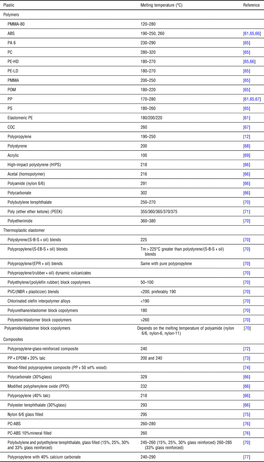
Table II shows some of the injection molding materials frequently used. For easy identification of the polymer-based materials used in injection molding, it can be usually categorized into commodity plastics, engineering plastics, and HPP engineering plastics. Commodity plastics cover the major group of plastics with a wide range of applications, such as tubing, films, packaging, labware, connectors, etc.[Reference Sastri78,Reference Sastri79] Engineering plastic is the second group of plastics and products under this class are related to electrical and mechanical properties applications.[Reference Maddah80] HPPs are usually used as implants in medical application or as components in automotive, aerospace, and structural applications.[Reference Sastri78,Reference Pye81] Crystallinity classification, such as semi-crystalline and amorphous, is important in selecting polymer materials for injection molding. The semi-crystalline structure is composed of a small crystalline region and amorphous regions.[Reference Callister43] Crystalline regions have high periodicity and anisotropy, while the amorphous regions are randomly oriented (isotropic) and have higher free volume.[Reference Callister43] The crystallinity of polymers has an effect on the end product of the injection molding process. More crystalline polymers tend to have a higher mold shrink and wear resistance as compared to amorphous polymers. On the other hand, amorphous polymers tend to have good impact properties.[Reference Sastri78] Another important property that needs to be examined before the injection molding process is understanding the melt flow characteristics of polymers. In cavity filling, viscosity is an important polymer processing property that needs to be considered. Viscosity represents the resistance to flow, while the melt flow index (MFI) pertains to the grams per 10 min pushed out of a die of prescribed dimensions.[Reference Polychronopoulos and Vlachopoulos82,Reference John Vlachopoulos83] In the injection molding process of filling the cavity with part material, the shear rate can reach up to 10,000 s−1 and MFI ranging from 5 to 50.[Reference Polychronopoulos and Vlachopoulos82] Khan et al. predicted the effect of viscosity and shear rate on the mold cavity concerning melt temperature. It can be concluded in their research that high melt temperature can achieve the lower effect of viscosity and the higher shear rate.[Reference Khan and Acharya10]
Injection molding materials.[45–Reference Redwood64]

Another important feature of rapid tooling is the design of the cooling channel in the mold that increases the speed of solidification.[Reference Imihezri, Shaharuddin and Salit84] The cooling time of the mold and injected part constitutes a larger portion of the overall production cycle that can be reduced through different techniques such as optimization of the cooling channel used in injection molding.[Reference Jahan, Wu, Zhang, El-Mounayri, Tovar, Zhang, Acheson, Nalim, Guo and Lee85] Research made by Hassan et al. showed that the rectangular cross-section cooling channel reduces the time to completely solidify the part material and conclude that the cooling channel near the artifact surface improves the efficiency of the cooling channel.[Reference Hassan, Regnier, Le Bot and Defaye86] Research made by Rizvi indicates that an increase in mold temperature results in an increase in crystallinity for the molded specimen. Also, crystallization of isotactic polypropylene (iPP)-molded specimens was influenced by elongation and shear rate in the mold cavity. It can be noted that semi-crystalline polymers with shorter relaxation time exhibit a skin-core morphology type of structure.[Reference Rizvi12] Slow-cooled parts indicate greater mold shrinkage that is related to the thermal coefficient of expansion and the presence of crystallinity in the part.[Reference Frizelle11] Shrinkage values for the amorphous injected part were at the range of 0.003–0.007 inches per inch while the crystalline material was at the range of 0.015–0.030 inches per inch.[Reference Frizelle11]
Effect of weld lines, warpage, and shrinkage to injection-molded parts
Shrinkage and warpage in a thin-walled part material in injection molding are greatly affected by the mold packing pressure.[Reference Azaman, Sapuan, Sulaiman, Zainudin and Khalina74] Ozcelik et al. compared the plastic part with and without weld line in terms of impact and tensile strengths. Through simulation using the Moldflow software, they found out that weld lines greatly affect the impact strength of the injected part. Comparison between parts with weld lines and without weld lines was made by varying packing pressure and melt temperature.[Reference Ozcelik, Kuram and Topal87]
Research made by Dzulkipli and Azuddin indicates that mold design, the type of material, and melt temperature affects the formation of weld lines. Dzulkipli and Azuddin used a polypropylene-glass-fiber-reinforced composite as part material in the injection molding process. An increase in melt temperature results to decrease in the formation of weld lines, and composites with higher filler composition resulting in a shorter weld line length and a wider weld line angle.[Reference Dzulkipli and Azuddin72] Mold shrinkage is the difference between a cavity dimension and the corresponding dimension of the part that came from that cavity. Slow cooling of the parts during the injection molding process tends to have greater mold shrinkage as compared to fast cooling of parts. Also, the coefficient of thermal expansion and the presence of crystallinity contribute to mold shrinkage.[Reference Frizelle11] The shrinkage rate of several commonly used thermoplastics is given in Table III.[Reference Bralla88]
Shrinkage of selected polymer materials used in injection molding.[89]

LyondellBasell researchers suggested several mechanical test procedures and sample preparations for polyolefins.[90] Adhikari et al. reported on the measurement of residual stress in injection-molded polymethyl methacrylate (PMMA) using low birefringence polariscope (LBP).[Reference Adhikari, Bourgade and Asundi29] Another study used computer-aided engineering (CAE) and comparison with experimental measurements in order to understand the relationship between the residual stress and deformation after thermal cycling.[Reference Kim and Min30]
Quality of injection-molded parts
For the injection molding process, productivity and quality are two important contradictory objectives, but are needed to be seriously considered. Singh and Verma also presented a brief review of the performance parameters and methods related to injection molding.[Reference Singh and Verma91] Another group reported on the different models and control methods used in injection molding.[Reference Chen and Turng92] Amer et al. used the Taguchi method and analysis of variance (ANOVA) in order to reduce warpage defect of a thin-plate acrylonitrile butadiene styrene (ABS) material. They identified that injection pressure, packing time, and cooling time contributed to warpage defect in injection-molded ABS material.[Reference Amer, Moayyedian, Hajiabolhasani and Moayyedian93] Another group also used the Taguchi method in designing plastic injection mold in order to reduce warpage. They observed that the melt temperature has the greatest effect on the warpage of the part. Specifically, they reported that the ideal temperature should be 240°C, the filling time should be 0.5 s, the packing pressure 90%, and the packing time 0.6 s.[Reference Tang, Tan, Sapuan, Sulaiman, Ismail and Samin77] Masato et al. reported on the impact of processing conditions on dimensional accuracy (including shrinkage and warpage) of thin-wall fiber-reinforced injection-molded parts. The rationale behind is that highly shear-stressed melt flow would cause shrinkage and warpage of the part. They used x-ray computed tomography for the analysis, and they found out that melt temperature and packing pressure were the primary factors causing the shrinkage of thin-wall parts.[Reference Masato, Rathore, Sorgato, Carmignato and Lucchetta34]
Mold flow analysis and finite element analysis of mold filling
Tang et al. used a commercial software to design a mold and also perform thermal analysis.[Reference Tang, Kong, Sapuan, Samin and Sulaiman94] They found out that uneven cooling occurs in the mold and that shrinkage occurred in the regions near the cooling channels.[Reference Tang, Kong, Sapuan, Samin and Sulaiman94] Teklehaimanot, in his thesis, designed a joint credit card and USB flash drive holder, using a commercial software to design and analyze the material flow and product defects in an injection molding process. Parameters, such as fill time, fill pattern, clamping force, and type of material, were varied.[95] Stratasys introduced a CAE software which may be used to understand the effect of process conditions, material properties, part design, and mold design on part quality. Specifically, the software can be used to analyze mold filling, packing, cooling, and warpage after molding. Essentially, the software helps in the evaluation, verification, and optimization of design parameters for 3D-printed injection molds.[45]
Overview of 3D printing
3D printing process
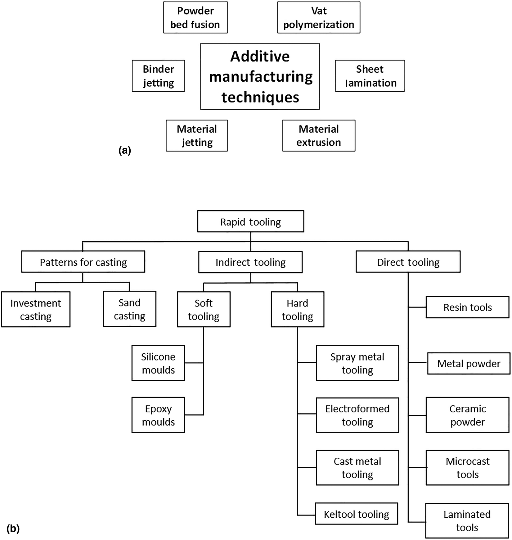
AM starts with the preparation of a 3D model using either 3D scanning or 3D computer-aided design (CAD).[Reference Dizon, Espera, Chen and Advincula5] The 3D model will then be converted into a .stl file format.[46] The .stl file of the model is then prepared and sliced into several hundred or thousands of layers using a slicing software, which will depend on the 3D printer to be used. The slicing software is important to be able to set and optimize the printing parameters and be able to produce quality parts.[Reference Sai and Yeole47] The slicing software will also convert the .stl file into the appropriate file type for the 3D printer to be used.[Reference De Leon, Chen, Palaganas, Palaganas, Manapat and Advincula48]Figure 1(a) shows the different categories of 3D printing technologies.[Reference Dizon, Espera, Chen and Advincula5,Reference De Leon, Chen, Palaganas, Palaganas, Manapat and Advincula48,Reference Dizon, Chen, Valino and Advincula49] And the common 3D printing technologies for plastics include stereolithography (SLA), fused deposition modeling (FDM), selective laser sintering (SLS), digital light processing (DLP), three-dimensional printing (3DP), laminated object manufacturing (LOM), polyjet technology, etc. The mechanical properties of 3D -printed parts are dependent on build orientation and other printing parameters.[Reference Dizon, Espera, Chen and Advincula5] Polymer nanocomposites are also being considered to make a more mechanically robust 3D-printed part.[Reference Dizon, Espera, Chen and Advincula5,Reference De Leon, Chen, Palaganas, Palaganas, Manapat and Advincula48,Reference Dizon, Chen, Valino and Advincula49]
(a) Categories of 3D printing technologies and (b) categories of rapid tooling. Reproduced with permission from Ref. [Reference Rosochowski and Matuszak51] [Copyright (2000), (Elsevier)].

3D printing of molds for injection molding applications and rapid tooling
Rapid tooling is the use of AM techniques to create mold or die, either directly or indirectly, with shorter lead time than conventional manufacturing techniques.[46,Reference Afonso, Pires, de Sousa and Torcato50] Rapid tooling can be categorized into three, such as direct tooling, indirect tooling, and pattern for casting, as shown in Fig. 1(b).[Reference Rosochowski and Matuszak51] Direct tooling consists of the use of rapid prototyping technology, such as 3D printers, to produce tools that resemble the properties of actual tools.[Reference Afonso, Pires, de Sousa and Torcato50–Reference Jayanthi, Bokuf, Mcconnell, Speer and Fussell52] A typical application of direct tooling is for pre-production planning and low volume production requirements.[Reference Jayanthi, Bokuf, Mcconnell, Speer and Fussell52] Indirect tooling uses rapid prototyping technology to create patterns and then creates conventional molds from these patterns.[Reference Afonso, Pires, de Sousa and Torcato50,Reference Jayanthi, Bokuf, Mcconnell, Speer and Fussell52] Indirect tooling can be classified into the number of materials used. Soft tooling used polymeric tools to produce few production copies, while hard tooling involves the production of multiple parts before it wears.[Reference Afonso, Pires, de Sousa and Torcato50,Reference Rosochowski and Matuszak51]
The conventional manufacturing of injection molds requires the expensive and time-consuming tooling process. Molds that are made for high-volume production (millions of parts) require extreme durability and hardness/toughness that molds can stand hundreds of thousands of heating and cooling cycles without deformation.[Reference Chen and Liu53–Reference Rosato and Rosato55] Steel is normally used for such molds, but unfortunately, the fabrication process of steel involves expensive CNC milling, electrical discharge machining, and polishing. These tooling procedures can cost from tens to hundreds of thousands of dollars with lead time from 2 to 4 months.[Reference Jansen, Van Dijk and Husselman23,Reference Dewhurst and Boothroyd56] For low volume production, the time consuming and expensive fabrication of injection molds significantly increase the expense of production. In this case, 3D printing is the ideal technology which offers several advantages over traditional steel mold fabrication, listed below.[6,7,Reference Snelling, Li, Meisel, Williams, Batra and Druschitz57–Reference Chimento, Jason Highsmith and Crane59]
(1) Fast launching. 3D printing of injection molds only takes within days of concepts instead of several months. This is especially important for companies that are trying to create watershed opportunities for markets to launch new products, as well as for R&D departments for concept proof and prototyping.
(2) On-demand fabrication. The elimination of long-time and expensive production in 3D-printed molds allows the easy correction and changes made on existing molds. In conventional mold fabrication, every trivial modification or changes made in the molds, either for different application or for better performance, requires the remake of the mold, which is as time-consuming as making a new mold. 3D printing, therefore, can cut off several months to accomplish these modifications of molds.
(3) Cost-effective production. The cost of steel molds fabrication can be diluted by the mass production of parts. However, for low volume production, the dilution of expense is very limited which tremendously raises the price of the injection molded parts. This issue can be resolved by saving hundreds of thousands of dollars in mold fabrication using 3D printing.
(4) Freedom of geometry design. Complex-shaped geometry is very difficult to build among the traditional tooling process, and some structures are beyond the molding capability and require several parts assembling. The flexibility of 3D printing offers unparalleled freedom of the geometry design in mold fabrication, while the cost and processing time still remain low.
Polymer materials are normally used in 3D-printed molds for low volume production. High-temperature resistance, toughness, and hardness are essential for printed molds to stand above the melting temperature of injected materials.
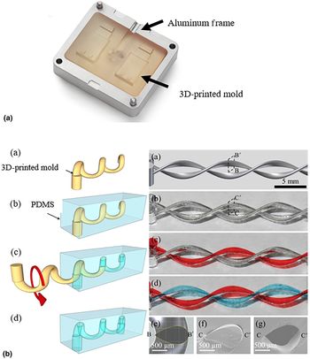
Photo-curable resins are one example which is 3D printed by SLA.[7] The high crosslinking density provides good thermal stability, while the high resolution offers a smooth finish. Formlabs have 3D-printed molds by using their photo-curable resins which successfully cast several complex-shaped objects. The molds, although mechanically tough with tensile modulus above 2 GPa, can only be used for molding plastics with low melting temperatures (below 230°C), such as low-density polyethylene (LDPE), PLA, polystyrene (PS), and PP. This is due to the low heat deflection temperature (below 200°C), which causes warping and bending after several cycles at high temperature. The printed molds are often encapsulated into aluminum frames before being inserted into injection clamp in order to improve the thermal durability of 3D-printed molds [shown in Fig. 2(a)]. The aluminum frame provides support against the pressure generated during the injection of molten plastics. It also prevents molds from warping and extension after repeated heating and cooling.
(a) 3D-printed mold fitted in the aluminum frame. Reproduced with permission from Ref. [7] (Formlabs, Inc.). (b) (left) Microfluidic channel using 3D-printed mold and (right) variable channel diameter, double-helix structure. Reproduced with permission from Ref. [Reference Hwang, Paydar and Candler60] [Copyright (2015), (Elsevier)].

Stratasys also has 3D-printed injection molds by using the another technique called PolyJet printing, in which photo-curable resins are jetted and cured by UV light right after.[6] Stratasys developed the Digital ABS, a two-component photo-curable material that combines high-temperature resistance and high toughness. To extend the heating cycles of printed molds, optimized cooling procedures are conducted such that the temperature in the cavity and core of molds remains below 58°C while injection molding ABS. Several companies and laboratories have adopted 3D-printed molds for prototype part production, for example, electronic components part with customer-facing interactive elements, cooling fans with the reduced noise level, etc. The adoption of 3D-printed molds have shortened the R&D process by up to 35% and saved 90% of costs.
Researchers have also studied the performance of 3D-printed molds in comparison with traditionally fabricated molds. It was found that the freedom of structural construction of 3D printing can provide unparalleled flexibility in designing the geometry of molds [e.g., Fig. 2(b)]. Chimento et al. have reported that the prosthetic/orthotic device, which requires high customizability according to the needs of patients and practitioners, can be easily fabricated by 3D-printed materials for rapid tooling.[Reference Chimento, Jason Highsmith and Crane59] Hwang et al. fabricated a 3D-printed microfluidic mold shown in Fig. 2(b) that allows the precise control of various device geometries, which is unattainable through existing tooling and molding routes.[Reference Hwang, Paydar and Candler60] Sachs et al. have 3D printed a mold for injection molding with specially designed conformal cooling channels that outperform the straight cooling channel fabricated by traditional tooling.[Reference Sachs, Wylonis, Allen, Cima and Guo22]
León-Cabezas et al. studied the fabrication of mold using (3DPolyjet) photopolymerization resin and observed similar properties to ABS (they call it ABS-like). A sequence of materials is used to inject in the ABS-like mold, such as elastomeric polyethylene (injection temperature of 95°C), polypropylene (injection temperature of 200°C), and ABS (injection temperature of 270°C). A total of 20 parts (six elastomeric PE, eight PP, and six ABS) were produced from the mold before crack failure was formed.[Reference León-Cabezas, Martínez-García and Varela-Gandía61] Research made by Noble et al. utilized an inkjet-style 3D printer Object350 Connex to prepare a mold from UV-curable acrylate resin. Injected parts in the 3D-printed mold produced a naturally wavy surface that would deflect light in unplanned directions making it unsuitable for artificial photosynthesis technology. Also, pronounced warping were detected with PP parts produced from 3D-printed molds.[Reference Ma, Gibson, Balaji and Hu62] Ma et al. used 20% alumina powder-filled epoxy composite as mold, while polypropylene and thermoelastic elastomer were used as part material for the injection molding process. Results indicate that alumina has poor thermal conductivity. Therefore, in order to reduce damage to the mold, cycle time was lengthened. The above-mentioned material for printing molds is applicable for low volume production.[Reference Ma, Gibson, Balaji and Hu62] Research made by Rahmati and Dickens utilized SLA injection mold tooling by using SL epoxy that utilized 500 injection parts made of PP and ABS. Failure of the molds was either due to the excessive flexural stress or shear stress during the injection molding process. The temperature of the epoxy mold must be reduced to 45°C before the start of the another cycle.[Reference Rahmati and Dickens63]
Sachs et al. made a comparison of 3D-printed molds with conformal channels and machined mold made of a 303 stainless steel with straight channels. Results indicate that 3D-printed molds with conformal channel exhibited a more uniform surface temperature than the insert machined with the straight channel.[Reference Sachs, Wylonis, Allen, Cima and Guo22]
3Dhubs has also reported on 3D printing low-run injection molds. They briefly discussed injection molding, 3D printing, 3D-printed mold configurations, and the design of 3D-printed injection mold. SLA and Material Jetting processes were used.[Reference Redwood64] Javelin also reported on using a digital ABS material with 30-µm layer thickness and 0.1 mm accuracy.[96] Researchers from Fraunhofer IPA introduced the additive freeform casting process. They used the FDM technology to create molds made of polyvinyl acetate (PVA), which is water-soluble. The mold was then filled with epoxy resin or polyurethane. After drying/curing, the mold was then removed by immersing the whole part in water.[Reference Watkin97] The difference with the current study and previous studies (including these three references) are the following: technologies used, materials used for printing, the material used for injection molding, the repeated number of shots made, as well as the investigation of the damage mechanism in each of the configurations.
HPP materials for 3D printing
Metal 3D printing of molds, even though having excellent mechanical properties, is still a costly alternative due to the expensive metal 3D printer available in the market. With this, it is very important to consider using polymers or polymer nanocomposites as molds for injection molding applications. For polymers to be used for this purpose, the high-performance polymers and polymer nanocomposite materials should be considered. Several studies show important reviews regarding different high-performance materials which may be considered to be used.[Reference Dizon, Espera, Chen and Advincula5,Reference De Leon, Chen, Palaganas, Palaganas, Manapat and Advincula48,Reference Dizon, Chen, Valino and Advincula49]
A demonstration of injection molding using 3D-printed polymer molds
Materials and methods
Printing technologies, molding materials, and injected materials
Two types of 3D printing technologies were used to print the molds, namely SLA and FDM. For the SLA 3D printing method, the mold was printed using a Formlabs Form 2 SLA 3D printer having a Class 1 405 nm violet laser and a build volume of 145 × 145 × 175 mm. The printer has a laser spot size of 140 µm and power of 250 mW. Layer thickness (i.e., printing resolutions) of 25, 50, and 100 µm are achievable using this printer. For the FDM 3D printing of molds, the first printer used was the Zortrax M200, which has a build volume of 200 × 200 × 180 mm, a resolution of 90–400 µm, precision: XY 0.015 mm, Z 0.0025 mm, nozzle diameter of 0.4 mm, maximum extrusion temperature of 380°C, it also has a perforated heated bed. The details of the printers used and the materials used for printing of the molds are given in Table IV, while the specifications of the 3D printers are given in Supplementary Table S1. The injected material used for all experiments is PLA.
3D printers and materials used for 3D printing of molds.

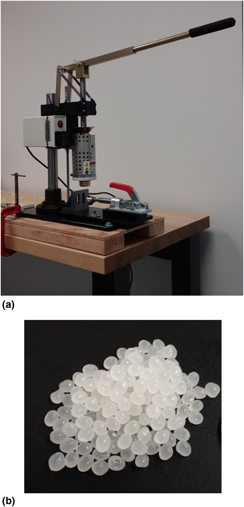
The model 150A benchtop plastic injection molding machine from LNS Technologies shown in Fig. 3(a) was used for the study. It operates on 120 VAC, 400 W, and 50/60 Hz. The shot capacity is 1.1 cu. in./19 g (PS). The maximum operating temperature is 490°F and the maximum outside dimension of the mold is 8.0″W × 5.0″H × 5.0″D. It is suitable to be used for aluminum molds. The commercially available PLA pellets used for the study are also shown in Fig. 3(b).
(a) Benchtop injection molding machine and (b) polylactic acid (PLA) pellets.

3D-Printing of molds
The first step was the creation of the 3D CAD model of the molds using a commercial software, Solidworks. The model was then saved as a .stl file. The .stl model/file was then sliced into many layers. The sliced file was then sent/saved to the 3D printer. Then, the 3D printer printed the molds. The molds were printed with the cavity facing upwards to avoid generating supports which could affect the smoothness of the surface of the cavity. The molds, including cavity, were designed to fit the dimensions of the injection molding machine, the 1.1 cu. in. injection capacity of the machine, the build volume of the Form 2 3D printer. After printing the molds, the parts were rinsed in a bath of isopropyl alcohol for 10 min. The mold was then air-dried.[Reference Dizon, Chen, Valino and Advincula49,Reference Afonso, Pires, de Sousa and Torcato50]
Injection molding process parameters
Since a manual benchtop injection molding machine has been used for the study, only the injection temperature of ~210°C, mold temperature of ~35°C, and ejection waiting time of 1.5 min have been maintained.
Results and discussions
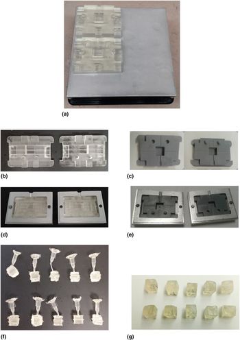
Figure 4(a) shows a mold, printed using the Formlabs clear resin, attached to the build plate of the SLA 3D printer after printing. Since the mold has been printed with the cavity facing upward, the flat side of the mold was attached to the build plate, making it a little difficult to remove. The original design (.stl file) of the mold has cavity dimensions of 15.00 mm × 15.00 mm × 15.00 mm. However, the 3D-printed mold size when measured has cavity dimensions of 14.86 mm × 15.6 mm × 15.06 mm. On the other hand, for the ABS material printed using FDM, the mold cavity dimensions were 15.12 mm × 15.25 mm × 15.07 mm. These data show that the dimensions of 3D-printed parts produced using current 3D printing technologies still do not produce parts with very accurate dimensions.
(a) 3D-printed molds attached on the build plate of Formlabs Form 2 3D printer (after SLA printing); (b) printed molds using the Formlabs clear resin; (c) printed molds using Zortrax ABS plastic; (d) 3D-printed molds made of clear resin encapsulated in aluminum mold frames; (e) 3D-printed molds made of ABS plastic encapsulated in aluminum mold frames; (f) samples of injection-molded cube parts using the Formlabs Form 2 clear resin 3D-printed molds before removal of the waste plastic; and (g) samples of injection-molded cube parts using Zortrax M200 ABS 3D-printed molds after removal of the waste plastic.

Figures 4(b) and 4(c) show 3D-printed molds produced using different techniques and materials as given in Table IV. Figures 4(b) and 4(c) show the molds printed using the Formlabs clear resin and the Zortrax ABS filament, respectively. Figures 4(d) and 4(e) show some 3D-printed molds encapsulated in blank aluminum mold frames. The blank aluminum mold frames were sourced from the supplier of the injection molding machine. The molds were encapsulated into blank aluminum frames to provide structural support against the stresses during the injection molding process. The frames also protect the molds from the heat of the nozzle of the injection molding machine. The aluminum frames could ensure the longer useful life of the 3D-printed polymer molds. The researchers designed the molds that would lessen the printing time and materials used. The sturdiness of the mold, however, was not sacrificed.
Sample injection molding
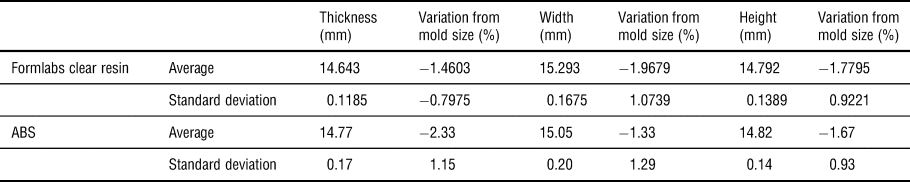
Figure 4(f) shows samples of injection-molded cubes produced using SLA 3D-printed molds (Formlabs Form 2/clear resin). The waste plastic materials, seen in Fig. 4(f), are from several areas, namely overflow, sprue, gate locations, and runners. The dimensional accuracy of injection-molded parts has been investigated. This was done by measuring the length, width, and height of the cube, and comparing the values with the designed dimensions, i.e., 15.00 mm for all sides, as well as the measured dimensions of the cavities of the printed molds. The measurements from 10 samples were recorded. The average values and standard deviations from the 10 samples have been computed. The measured values are given in Supplementary Tables S2 and S3. The summary is given in Table V. Supplementary Table S2 shows the values obtained using the Formlabs Form 2 clear resin Mold. From the table, it can be seen that the dimensions of injection-molded parts have little variation with the first injected part, as well as with the dimensions of the mold, i.e., below 5% variation from reference dimensions.
Summary of accuracy measurements using 3D-printed molds.
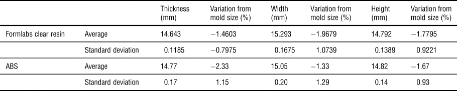
Supplementary Table S3 shows the values obtained using Zortrax ABS. Figure 4(g) shows the sample of injection-molded cubes produced using the ABS 3D-printed mold from Zortrax. Similarly, with the case of the Formlabs clear resin, the average variation of the dimensions are below 5% when compared with the mold size.
Failure analysis of SLA-3D-printed mold
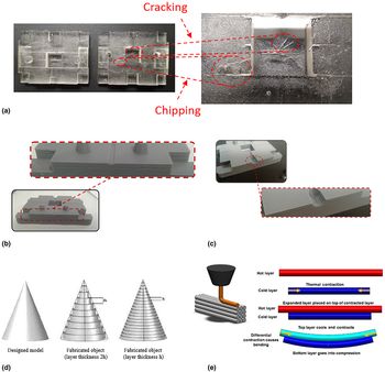
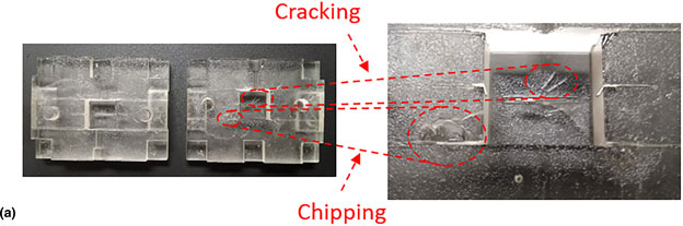
An endurance test was also conducted for the mold 3D-printed using the Formlabs clear resin. For the test, PLA pellets were injected into the mold multiple times in order to know how many parts the mold can produce before any significant fracture occurs. The clear resin showed cracks after 30 shots, and eventually chipping after 60 shots, as shown in Fig. 5(a). The reason could be due to the combined effect of transverse tension experienced by the mold during part removal and thermal cycles during the process of injecting molten plastic material. More tests (e.g., transverse tension tests and peel tests) are needed in order to fully understand the damage mechanism in 3D-printed plastic molds.
(a) Cracking and chipping of 3D-printed mold made of the Formlabs Form 2 clear resin after multiple shots of molten PLA plastic. (b) Layer delamination occurred in 3D-printed ABS mold (FDM). (c) Delamination due to transverse tensile stresses experienced by the molds during part removal. (d) Schematic of the stair-step effect resulting from layer-wise fabrication.[Reference Quan, Wu, Keefe, Qin, Yu, Suhr, Byun, Kim and Chou98] Reproduced with permission from Ref. [Reference Quan, Wu, Keefe, Qin, Yu, Suhr, Byun, Kim and Chou98] (Copyright [2015], [Elsevier]). (e) Schematic of uneven cooling during the layer fabrication of FDM-printed parts. Reproduced with permission from Ryan Carlyle.[89]

Failure analysis of FDM-3D-printed mold
Figure 5(b) shows the layer delamination which occurred in the mold printed using an FDM technique (Zortrax M200, ABS filament). This delamination was observed just after printing, i.e., before being used for injection molding. This could be due to warping and thermal contraction of layers intrinsic to the FDM technique. Figure 5(c) shows an increase in a layer gap size after 10 shots due to delamination caused by transverse tensile stresses during part removal.
One of the major reasons for layer delamination in FDM printed parts was the weak interlayer bonding brought about by the so-called stair-step effect on its surface. Figure 5(d) shows the schematic of the stair-step effect from layer-wise fabrication. It shows the smooth surface from the CAD model to the rough surface of the fabricated (i.e., 3D-printed) object with a varying layer thickness (1 or 2 h). Smaller resolutions can reduce the effect of the stair-step effect, but it depends on the minimum resolution of the 3D printer being used.[Reference Quan, Wu, Keefe, Qin, Yu, Suhr, Byun, Kim and Chou98]
The delamination on FDM-printed parts is usually due to the warping stress. Warping stress is caused by the repeated thermal contraction of a hot layer plastic on top of a cold layer plastic during the material extrusion of FDM printer. The schematic on how warping stress is being developed during the FDM extrusion is shown in Fig. 5(e).[89] The FDM process adds a hot layer on top of a cold layer and sticks to it. The hot layer contracts when the temperature decreases. The new layer is stuck with the previous layer that is already fully cooled or contracted. This process generates shear stress between the two layers. The shear stress developed between the layers tends to accumulate due to the repeated cycle of the layer-by-layer addition of FDM, and thus, generates a large-scale bending force on the FDM-printed part. The temperature control with the environment during the printing cycle can minimize the effect of warping stress and delamination. It reduces the effect of uneven cooling between layers during the layer-by-layer addition of materials.[89]
These results would show that SLA-printed molds are ideal for a small-scale production facility needing to produce medium-scale quantities, which can mean eliminating the need for using commonly used but expensive metallic molds. These results also show that the ABS-printed molds using the FDM technique may not yet be used for rapid tooling in injection molding applications. Alternatively, perhaps, additional post-processing to enhance the interlayer bonding is needed. Additionally, as pointed out in the discussions, the temperature should be controlled in order to warping, bending, and eventual delamination of the part.
What is evident is the need for better polymer materials perhaps in the form of toughened high-performance polymer materials or the use of even thermosets and crosslinking to improve fracture resistance and delamination. The previous work on the use of nanocomposite 3D-printed materials for evaluating improvements in thermo-mechanical properties has shown methods of improving semi-crystalline thermoplastics and thermoset materials using commonly available 3D printing methods such as FDM and SLA. Another consideration could be heat transfer and thermal properties that represent optimized condition in various injection molding stages. Clearly, this is a rich area for material research. Progress in this hybrid manufacturing process would open up more opportunities also for other technological fields.[Reference Dizon, Espera, Chen and Advincula5,Reference De Leon, Chen, Palaganas, Palaganas, Manapat and Advincula48,Reference Espera, Dizon, Chen and Advincula99,Reference Chen, Mangadlao, Wallat, De Leon, Pokorski and Advincula100]
Summary and conclusions
AM and its uses for tooling, casts, dies, and molds are envisioned to revolutionize FM through cost and time-savings. Metals and alloys dominate tooling and mold fabrication, while polymer materials can offer unique advantages in cost and time but have inherent disadvantages. While other FM methods have their tooling needs, the emphasis on this Prospective has been the injection molding process. A more comprehensive overview of the tooling design and material requirements were given in hopes of outlining the challenges ahead in fabrication and material requirements. Yet, a number of attempts have been reported that use 3D printing of materials including polymer materials to demonstrate the possibilities of design prototyping and rapid tooling. The possible combination of 3D-printed molds has also been demonstrated. The study showed that UV-curable resins could be used as molds for injection molding. The dimensional accuracy of the injected parts is good considering that the average variation from the first-injected part and the mold size is below 5% (using both SLA-printed molds). FDM-printed molds can be used in direct rapid tooling for the limited number of shots in injection molding. With the results, it can be concluded that this setup for SLA-printed molds is feasible for a small-scale production facility needing to produce medium-scale quantities with low melting temperature plastics such as PLA, thereby eliminating the need for using commonly used but expensive metallic molds. There are a number of opportunities for polymer and nanocomposite research to enable true rapid tooling with toughened materials using 3D printing.
Supplementary material
The supplementary material for this article can be found at https://doi.org/10.1557/mrc.2019.147.
Acknowledgments
This work is supported by the Department of Science and Technology—Philippine Council for Industry, Energy, and Emerging Technology Research and Development (DOST-PCIEERD) and PETRO Case. A portion of this work (R.C.A and Q.C.) is funded by the Department of Energy's Kansas City National Security Campus, operated by Honeywell Federal Manufacturing & Technologies, LLC, under contract number DE-NA0002839.
Disclaimer
The Department of Energy’s Kansas City National Security Campus is operated and managed by Honeywell Federal Manufacturing & Technologies, LLC under contract number DE-NA0002839.