I. INTRODUCTION
The unlicenced 57–64 GHz frequency band has attracted considerable interest worldwide, for use in short-range, multi-gigabit communication for different purposes, such as gigabit ethernet, high-definition video transmission, etc [Reference Floyd, Reynolds, Pfeiffer, Zwick, Beukema and Gaucher1]. The design of components for use at these frequencies is subject to several constraints, however, including power consumption restrictions, mass producibility, and superior performance at low cost. As a result, it is desirable to reduce the size of digital wireless transmission and reception systems by using direct upconversion and downconversion [Reference Abidi2]. This can lead to savings in integrated circuit chip count and is gaining acceptance at low microwave frequencies. At higher millimetre-wave frequencies however, this technique can suffer from local oscillator (LO) signal leakage to the antenna because filtering is difficult given that the carrier signal and its sidebands are very close in frequency.
A subharmonically pumped (SHP) mixer using an antiparallel diode pair simplifies the filtering problem. The fundamental LO signal is well-separated in frequency from the desired signal and the second harmonic is confined within the diode pair and therefore does not appear at the output [Reference Maas3–Reference Fujishiro, Ogawa, Hamada and Kimura5]. Moreover, simpler and lower-cost oscillators can be used since the required LO signal has half the frequency of what is required for a conventional mixer.
The SHP mixer using a pair of antiparallel diodes is a good candidate for low-power systems because it reduces the number of multiplier stages, requires no DC power, and can be used for both up- and downconversion [Reference Itoh, Shimozawa, Kawakami, Iida and Ishida6–Reference Lin, Lin, Lai, Chang and Wang8]. Single sideband (SSB) mixers also have low conversion loss and high image rejection, both very desirable properties. However, the required power dividers and combiners must have very accurate amplitude and phase responses.
SSB SHP mixers require several passive components, which traditionally occupy a large portion of the integrated circuit. The mixer, for upconversion, requires an in-phase LO power divider and a quadrature hybrid at the radio frequency (RF) output. For the LO divider, each arm of the circuit measures λLO/4, while each branch of the hybrid measures λRF/4. In addition, two stubs are required in the mixer itself, a λLO/4 open-circuit stub and a λLO/4 short-circuit stub, consuming even more (costly) real estate [Reference Itoh, Iida, Sasaki and Urasaki9, Reference Lin, Lai, Chiu and Wang10]. Clearly, it would be very beneficial to be able to reduce the footprint of these passive structures without sacrificing the mixer's performance.
In this paper, a compact SSB SHP up-converting mixer MMIC at 60 GHz is proposed. The mixer directly upconverts 100 MHz I and Q signals to 60.1 GHz using a 30 GHz LO. The circuit was fabricated in OMMIC's ED02AH process. It uses two pairs of 0.18 µm pHEMT-based diodes, each having two 15 µm fingers.
The SSB SHP upconverter was designed in uniplanar technology using coplanar waveguides (CPW) because of the unique combination of passive structures that can be realized. The potential to combine (CPW) and coplanar stripline (CPS) transmission lines, as well as the ability to realize both series and shunt matching stubs allows a greater amount of freedom when optimizing circuit performance than is possible in a conventional microstrip circuit [Reference Hettak, Beland, Verver, Stubbs and Morin11]. This freedom results from two main characteristics of coplanar layout: first, the characteristic impedance of a transmission line is determined by conductor width and gap spacing, both of which can be adjusted by the designer (only the signal conductor width may be adjusted for a given process in microstrip). Second, series stubs may be realized with relative ease in CPW and CPS designs, which is not the case in microstrip. Furthermore, isolation between transmission lines is improved due to the ground plane separating signal traces. Illustrating this design freedom, this mixer includes a Wilkinson power divider which has been miniaturized by 50% using asymmetric coplanar striplines (ACPS), along with novel matching structures that are patterned inside the centre conductor of CPW transmission lines. As will be discussed, both of these techniques greatly reduce the circuit area.
This paper is organized as follows. In Section II, the design of a subharmonic mixer is discussed, including novel miniaturization of its passive components. Section III presents a size-reduced Wilkinson power divider and a quadrature hybrid. These components are required to implement the SSB converter. The work presented in the previous two sections culminates in Section IV, where all of the circuit components (the subharmonic mixer, the Wilkinson power divider, and the quadrature hybrid) are assembled to yield a SSB upconverter mixer, which is characterized. Finally, Section V presents some concluding remarks. Throughout the paper, the design of each component (including the complete SSB SHP upconverter) is validated by measurements of fabricated prototypes.
II. DESIGN OF THE NOVEL SHP MIXER CORE
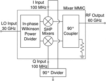
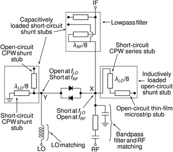
The SSB mixer circuit's design is centered on two pairs of antiparallel diodes. In-phase and quadrature signals are fed independently to the diode pairs along with the 30 GHz LO signal that is fed to the diode pairs through a miniaturized ACPS Wilkinson power divider. The second harmonic of the LO mixes with the IF signal to produce the desired 60 GHz RF signal. Owing to the antiparallel diode combination, even order mixing products (mf LO ± nf IF, where m + n is even) are suppressed. Meanwhile, the upconverted 60.1 GHz RF output signals are combined in a coplanar branch-line coupler. Figure 1 shows a block diagram of the mixer, while Fig. 2 shows a simplified schematic of the SHP mixer.
Block diagram of the SSB SHP upconverter.

Simplified schematic of the SHP mixer.

A) Circuit description
A conventional SHP mixer includes a λLO/4 open-circuit shunt stub and a λLO/4 short-circuit shunt stub to provide isolation between the RF and LO ports [Reference Hettak, Beland, Verver, Stubbs and Morin11]. However, the quarter-wavelength transmission lines are very long and will consume a large amount of chip area. To reduce the stubs' footprint, each was designed as a loaded CPW combination as outlined in [Reference Hettak, Verver, Stubbs and Morin12].
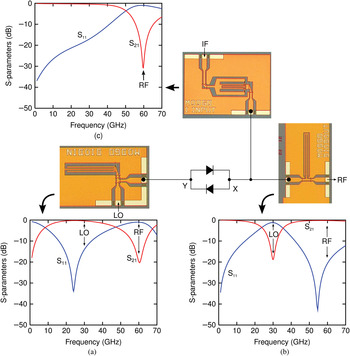
The λLO/4 short-circuit CPW shunt stub was miniaturized by loading it capacitively with an open-circuited CPW shunt stub, as shown in Fig. 2. The size-reduced stub is shown as point “Y” in the figure, on the LO port side of the antiparallel diodes. The stub provides an open-circuit at f LO while simultaneously acting as a short-circuit at f RF (where f RF = 2f LO + f IF ≈ 2f LO). The capacitively-loaded shunt stub was optimized to minimize the presence of f RF at the LO port. S-parameters for this circuit are shown in Fig. 3(a).
Circuit performance of (a) a CPW shunt stub loaded capacitively by an open-circuit stub, (b) an open-circuit shunt stub loaded inductively by a short-circuit shunt stub, and (c) a low-pass filter consisting of a short-circuit series stub loaded by an open-circuit shunt stub.

In a similar fashion, the λLO/4 open-circuited shunt stub was reduced in size with a short-circuited CPW series stub as shown in Fig. 2. This provides inductive loading of the transmission line. This stub is shown connected to point “X” in Fig. 2 and is found on the RF port's side of the antiparallel diodes. This stub acts as a short-circuit at f LO and an open-circuit at f RF. This inductively loaded stub was optimized to minimize the insertion loss at f RF. Data for this circuit are shown in Fig. 3(b).
In both cases, the stubs described above were reduced from lengths of λLO/4 to λLO/8. This corresponds to a size reduction of about 50%.
In addition, the IF input to the mixer includes a low-pass filter, which prevents the RF signal from reaching the IF port. The low-pass filter was realized with a λRF/8 short-circuit CPW series stub, which is loaded by an λRF/8 open-circuited shunt stub. This combination results in a high-impedance at f RF at point “X” in Fig. 2, the junction of the two diodes on the RF side. S-parameter results for this circuit are shown in Fig. 3(c).
Finally, an RF bandpass filter is also present to provide isolation between the RF and IF ports. Lumped L-C components placed in series were used to realize this filter.
B) Experimental results for the reduced-size SHP mixer
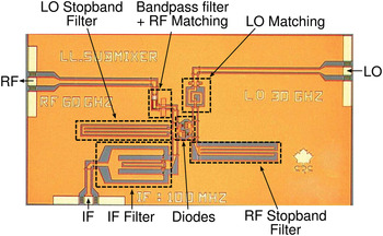
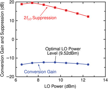
The SHP mixer core was fabricated and measured using a semi-automatic wafer probing station. A microphotograph of the mixer can be found in Fig. 4. 100 µm ground-signal-ground probes were used to perform the measurements. When a network analyzer was used, SOLT de-embedding structures were used to calibrate to the tips of the probes. Optimal mixer performance was obtained with an LO power of 9.5 dBm, as can be seen in Fig. 5.
Microphotograph of the SHP mixer core.

Measured gain and suppression plotted against LO power for the SHP mixer with f IF = 100 MHz and f LO = 30 GHz.

In addition, we can see from Fig. 5 that the 2f LO suppression is approximately 17 dB at this optimal LO power level. Since the SSB mixer includes two of these SHP mixers, we expect that the conversion gain will be improved by 3 dB in the final circuit. The entire SSB mixer's results are discussed in full in Section IV.
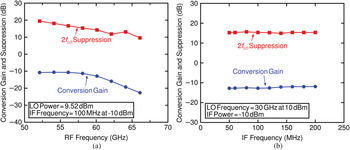
The conversion gain and suppression of mixer core versus RF are shown in Fig. 6(a). From this plot, the conversion gain is —11.8 dB ±1.0 dB from 52–62 GHz while the 2f LO suppression is better than 14 dB across the same band.
Measured gain and 2f LO suppression of the SHP mixer core plotted against (a) RF frequency and (b) IF frequency.

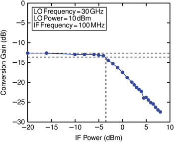
Similarly, for conversion gain and 2f LO suppression as a function of IF frequency, shown in Fig. 6(b), the curves are relatively flat. The conversion gain is measured to be −12.3 ± 0.5 dB up to 200 MHz, and the 2f LO suppression is 15.3 ± 0.4 dB. The 1 dB compression point is found for an input IF power of −3.5 dBm, as illustrated in Fig. 7.
Measured 1 dB compression point of the SHP mixer core.

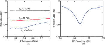
Finally, the return loss as a function of RF and IF frequency is shown in Fig. 8. The IF return loss is shown for frequencies of 26 GHz, 34 GHz, as well as for the nominal 30 GHz signal. Upon examination of the plot, we note that good performance is obtained for an IF up to 1 GHz, for a variety of LO frequencies. From Fig. 8(b), the RF return loss is better than 10 dB from approximately 54–59 GHz. The relative broadband nature of these results indicates that the circuit will perform well as a broadband upconverter in high data rate applications.
Measured return loss for the SSB mixer's (a) IF input for several LO frequencies and (b) RF output port.

III. SIZE-REDUCED WILKINSON POWER DIVIDER AND QUADRATURE HYBRID
In addition to the mixer core described in this section, some additional circuits are required for proper mixer operation. These include an in-phase LO power divider and an RF quadrature hybrid. This is achieved using a Wilkinson power divider, where its output is applied to the LO ports of each SHP mixer. The double-sideband suppressed carrier (DSB-SC) RF outputs from each mixer are combined in the quadrature hybrid, resulting in the suppression of the lower sideband (LSB). We recall that the 2f LO carrier is removed in each of the antiparallel diode pairs. The design of the Wilkinson power divider and quadrature hybrid are discussed in the following sections.
A) Miniature ACPS Wilkinson power divider
A standard Wilkinson power divider has two quarter-wavelength arms, which at the LO frequency of 30 GHz would consume considerable space. In order to reduce the substrate area required to implement the power divider, lines are often loaded inductively or capacitively using either lumped components or transmission line stubs [Reference Hirota, Minakawa and Muraguchi13, Reference Laneve, Hettak, Verver, Béland and Stubbs14]. Given CPS's excellent propagation characteristics at high frequencies [Reference Frankel, Whitaker and Mourou15] as well as a designer's ability to integrate both series shunt stubs, it is well-suited for realization of a size-reduced Wilkinson divider.
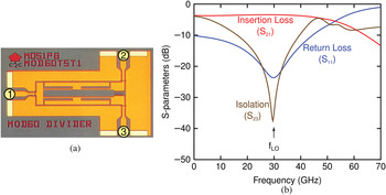
In this work, inductively-loaded ACPS transmission lines were used to realize the Wilkinson power divider. Short-circuit series ACPS stubs provide loading, which allows the length of the arms to be reduced by approximately 50%. Figure 9 shows a photograph of the power divider, along with the power divider's characteristics. Insertion loss is approximately 3.4 dB, while port isolation is approximately 35 dB at 30 GHz. The return loss is better than 20 dB from 26–34 GHz.
Characteristics of the miniature Wilkinson power divider. (a) A photograph of the fabricated divider. (b) S-parameter response of the power divider.

B) 90° CPW hybrid coupler
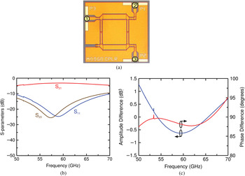
A quadrature hybrid combines the output from the two SHP mixers and eliminates the unwanted sideband. The amplitude and phase imbalance of the coupler has a great impact on the amount of sideband suppression. The coupler was realized using CPW. A photograph of the 60 GHz coupler is shown in Fig. 10(a) and its S-parameters are presented in Fig. 10(b).
Performance of the CPW 90° coupler. (a) A microphotograph of the fabricated coupler. (b) The coupler's S-parameters. (c) The amplitude and phase difference of the 90° quadrature coupler.

At 60 GHz, the return loss and isolation are better than 20 dB, while the insertion loss is 3.2 dB. Figure 10(c) presents the amplitude and phase difference. The amplitude varies from −0.6 to 1.3 dB from 50–70 GHz, while the phase difference varies from 87.4° to 95°, with even smaller variation around the 60 GHz band of interest.
IV. PERFORMANCE OF THE COMPLETE SSB SHP UPCONVERTER
In addition to the two SHP mixers present in the single-side mixer, the complete SSB mixer required an LO power divider and RF quadrature hybrid. The LO signal is split in-phase by the Wilkinson power divider. The resulting signals are applied to each SHP mixer's LO input while the I and Q baseband signals are applied at each mixer's IF input. The DSB-SC RF signals produced by each mixer are combined in the 90° hybrid, where one of the sidebands is cancelled. Suppression of the carrier (2f LO) is performed by each antiparallel diode pair. The outputs of the mixers described in Section II are combined using a quadrature hybrid. This removes the unwanted sideband. The level of sideband suppression provided by the complete circuit depends greatly on the amplitude and phase imbalance of the 90° hybrid, as well as the symmetry between the two mixers.
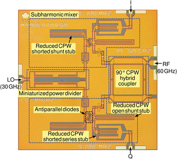
The upconverter was designed using the ED02AH foundry process from OMMIC and uses two pairs of 0.18 µm pHEMT-based diodes. Each diode has two 15 µm cathode fingers. The entire circuit measures 2.1 mm2 and is shown in Fig. 11. The layout of the two SHP mixers, the miniaturized Wilkinson power divider and the quadrature hybrid circuits requires very careful planning, to achieve as much symmetry as possible in the circuit and a minimum amount of parasitic coupling between components, all while reducing the substrate area consumed.
Microphotograph of the proposed miniature uniplanar 60 GHz SSB direct upconverter. The total circuit area is 2.1 mm2.

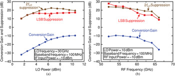
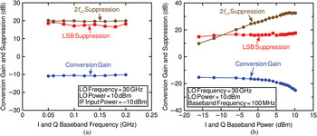
Figure 12(a) shows the mixer's conversion gain as a function of the LO input power level. The LO frequency is fixed at 30 GHz, while the I and Q baseband signals are at 100 MHz and −10 dBm power. Since only a single sideband should be produced by the circuit, the suppression of both the lower sideband and the second harmonic of the LO signal are also very important. As can be seen from the figure, conversion gain is largely constant for LO input powers of 8–10.5 dBm. As noted earlier, an improvement in conversion gain of approximately 3 dB is expected for the full upconverter, compared to only the SHP mixer core, and on examination of the plot, we can see that this improvement in gain is achieved.
Measured gain and suppression for the SSB SHP mixer, (a) as a function of LO power, (b) versus RF frequency.

The conversion gain is −10 dB ±1 dB and LSB suppression is better than 15 dB across the 52–61 GHz band, as can be seen in Fig. 12(b). For these measurements, the frequencies of the I and Q signals were fixed at 100 MHz, and their power levels were set to −10 dBm. The 30 GHz LO signal's power was set to 10 dBm, which is close to optimal. As can be seen in Fig. 12(b), the 2f LO suppression is better than 20 dB across the 52–61 GHz band.
The conversion gain as well as the 2f LO and LSB suppression, for variations in the in-phase and quadrature baseband signal frequencies are shown in Fig. 13(a). This figure shows that the lower sideband has been suppressed by at least 15 dB relative to the desired upper sideband over a band from 50 to 200 MHz. The carrier at 2f LO was measured as being suppressed by 20 dB over the same band.
Measured gain and suppression of the SSB SHP mixer (a) as a function of I and Q signal frequency, (b) as a function of I/Q power.

In the plot of Fig. 13(a), it can also be noted that the conversion gain and 2f LO suppression curves are nearly flat. However, there is some variation in LSB suppression as a function of the baseband frequency. Since a flat response is expected, variation in suppression indicates that there is a small phase or amplitude imbalance in the I and Q baseband signals.
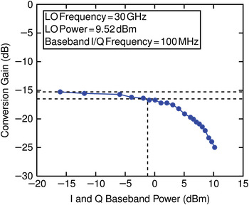
Figure 13(b) shows the gain and suppression of the mixer as a function of the baseband signal power. In this plot, we note that LSB suppression is largely constant with I and Q signal power. However, 2f LO signal suppression depends rather strongly on the baseband signals' power levels. In Fig. 14, the 1 dB compression point is shown. Since the 1 dB compression point is found at −1 dBm, a 2f LO suppression of approximately 25 dB is achieved.
Measured 1 dB compression point of the proposed SSB SHP mixer.

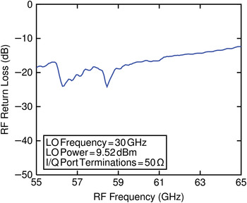
In Fig. 15, the RF return loss is shown as a function of frequency. As can be seen in the plot, the RF return loss is better than 10 dB over a 50–61 GHz frequency range.
Measured return loss for the SSB upconverter's RF output.

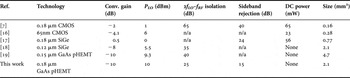
Table 1 shows a comparison between various aspects of the proposed upconverter and other upconverters found in the scientific literature. As shown in the table, the LO power required and conversion gain are similar and the circuit size compares favourably, given that the proposed upconverter also integrates additional circuitry to produce an SSB signal, which also introduces more loss. The performance characteristics of active direct upconverters are in general better than the proposed circuit, at the expense of static DC power consumption, and the passive upconverter requires a higher LO drive and exhibits higher conversion loss. The sideband rejection is weaker than desired principally due to the amplitude and phase imbalance of the coupler. With additional tuning of the coupler, the suppression could be improved.
Comparison of 60 GHz direct upconverters.

V. CONCLUSIONS
In this paper, a novel miniature 2.1 mm2 uniplanar, SSB, SHB upconverter MMIC operating at 60 GHz has been presented. The measured results indicate that reasonable performance is achieved from 52 to 62 GHz. It is demonstrated that uniplanar technology can be an attractive candidate for design of compact, high performance SSB SHP mixers.
The fabricated circuit yields a measured conversion gain of —10 dB, with LSB suppression better than 15 dB across a 52–61 GHz band. It was also shown that the RF port's return loss is better than 10 dB over a wide band and the 2f LO suppression is approximately 25 dB. The IF return loss was also found to be better than 18 dB up to 1 GHz, indicating that the upconverter can be used for wideband baseband signals.
In addition, the use of novel CPW and ACPS, series and shunt stub structures has also demonstrated that extensive size reduction of circuit components is possible, without sacrificing the mixer's performance. The use of such structures grants an MMIC designer a great deal of liberty. Compared to traditional structures, the design techniques presented allow design freedom, greatly reduced circuit area and the possibility of improved performance.
 Khelifa Hettak received the Dipl.-Ing. in telecommunications from the University of Algiers, Algeria, in 1990, and the M.A.Sc and Ph.D degrees in signal processing and telecommunications from University of Rennes 1, France, in 1992 and 1996, respectively. In January 1997, he joined the Personal Communications Staff of INRS-Télécommunications. He joined the electrical engineering department of Laval University, Quebec City, QC, Canada, in October 1998 as an Associate Researcher, where he was involved in RF aspects of smart antennas. In August 1999, he joined the Terrestrial Wireless Systems Branch at the Communications Research Centre (CRC), Ottawa, ON, Canada, as Research Scientist. He was involved in developing MMICs at 60GHz, low-temperature cofired ceramic (LTCC) packaging, RF MEMS switches, and GaN robust Tx/Rx modules. He is actively involved in microwave/millimeter-wave systems and related front-end analog electronic circuits, phased arrays, and satellite communication systems. He also is active in planar antenna design including wide scan-angle antennas at 60 GHz for wireless applications.
 Tyler N. Ross obtained the the B.Eng and M.A.Sc degrees, both in electrical engineering from the Université de Moncton, in Moncton, New Brunswick, Canada, in 2008 and 2010, respectively. He is currently pursuing the Ph.D degree in electrical and computer engineering at Carleton University, Ottawa, Ontario, Canada. His current research involves the modeling of microwave devices and the design of microwave integrated circuits.
 Nazish Irfan received his B.E. degree in Electrical from GEC Raipur, India in 1992, MASc in Electrical Engineering from University of Ottawa, Canada, 2007. Presently, he is a Ph.D candidate in University of Ottawa, Canada. His research interests include ad hoc sensor networks, neural networks and RFID.
 Gabriel Cormier obtained a B.A.Sc (electrical engineering) and an M.A.Sc (electrical engineering) from the Université de Moncton, in Moncton, New Brunswick, Canada, in 1998 and 2000, respectively. He received his Ph.D. in electrical engineering from Carleton University in Ottawa, Canada, in 2007. He has been an assistant professor at the Université de Moncton since 2006. His research interests include the design of millimeter-wave integrated circuits and devices, using GaAs and GaN substrates, as well as the use of evolutionary algorithms, such as genetic algorithms, particle swarm optimization, and ant colony optimization, applied to various engineering optimization problems.
 Mustapha C.E. Yagoub received the Dipl.-Ing. degree in Electronics and the Magister degree in Telecommunications, both from the École Nationale Polytechnique, Algiers, Algeria, in 1979 and 1987 respectively, and the Ph.D. degree from the Institut National Polytechnique, Toulouse, France, in 1994.
After a few years working in industry as a design engineer, he joined the Institute of Electronics, Université des Sciences et de la Technologie Houari Boumédiene, Algiers, Algeria, first as a Lecturer during 1983–1991 and then as an Assistant Professor during 1994–1999. From 1996 to 1999, he was head of the communications department. From 1999 to 2001, he was a visiting scholar with the Department of Electronics, Carleton University, Ottawa, ON, Canada, working on neural networks applications in microwave areas. In 2001, he joined the School of Information Technology and Engineering (SITE), University of Ottawa, Ottawa, ON, Canada, where he is currently a Professor.
His research interests include RF/microwave CAD, RFID design, neural networks for high frequency applications, planar antennas and applied electromagnetics. He has authored or coauthored over 350 publications on these topics in international journals and refereed conferences. He authored Conception de circuits linéaires et non linéaires micro-ondes (Cépadues, Toulouse, France, 2000), and co-authored Computer Manipulation and Stock Price Trend Analysis (Heilongjiang Education Press, Harbin, China, 2005).
Dr. Yagoub is a senior member of the IEEE Microwave Theory and Techniques Society, a member of the Professional Engineers of Ontario, Canada, and a member of the Ordre des ingénieurs du Québec, Canada.
 Gilbert A. Morin received the B.Sc.A. degree in engineering physics from Ecole Polytechnique de Montréal, Montréal, Canada, in 1977, and the M.A.Sc. and Ph.D. degrees in electrical engineering, from the University of Toronto, Toronto, ON, Canada, in 1980 and 1987, respectively. Since then, he has been working at the Defence R&D Canada - Ottawa, Ottawa, ON, Canada, as a Defence Scientist in the Advanced Military Communications Systems group. His research interests are GaAs MMIC, RFIC, microelectromechanical systems (MEMS), low-temperature co-fired ceramic (LTCC) packaging, reflector and lens antennas, phased arrays, and software-defined radio front-ends.
 Jim S. Wight has acted as a long-term consultant to the CAL Corporation, EMS, Vistar, Philsar, Conexant, IceFyre (where he was Principal Architect and Co-Founder), and AlleWin (where he was Chief Scientist and Co-Founder) throughout the past 25 years. He has pursued joint research with the Communications Research Centre (CRC) Canada, Ottawa, ON, Canada, in the areas of planar and dielectric resonator antennas, monolithic microwave integrated circuits, and superconducting microwave circuits, and with the Defence Research and Development Canada–Ottawa in the areas of spread-spectrum intercept, synchronization, and low-probability-of-intercept communications. He holds 30 U.S., Canadian, and European patents. Over the past 30 years, his research interests have focused on antennas, microwave circuits, and synchronizer circuits for wireless communications, radar, and radio navigation.