1. Introduction
It has long been recognized that quadruped mammals can be divided into rigid torso mammals and flexible torso mammals in nature. The torso plays an important role during the bounding gait of a mammal, and the spinal structure is important for a bio-inspired quadruped robot too. Many researches have been carried out on spinal parameters of quadruped robots in order to reveal the relationship between spinal structure and moving performance.
Early attempts have focused on quadruped robots with rigid torso. However, numerous studies have shown that this kind of robot can hardly run as fast as the robot with flexible torso, and the improved efficiency of the flexible torso model is also attributed to the torso’s compliance [Reference Cao and Poulakakis1]. In fact, it is a common scene that the quadruped mammals with flexible torso are better than those with rigid torso in their moving performance and adaptability to the unstructured environment. To make the robot perform better, researchers have tried other different approaches, such as flexible control strategy or flexible torso. For the control strategy, Adaptive Neuro Fuzzy Inference System (ANFIS) [Reference Bakırcıoğlu, Şen and Kalyoncu2] was put forward to control the leg’s trajectory. A successful navigation for legged robots needs posture control, trajectory control, and foothold computation, but all these controls enable robot’s control more difficult. A new framework [Reference Bazeille, Barasuol, Focchi, Havoutis, Frigerio, Buchli, Caldwell and Semini3] was proposed to solve this problem. Using the framework, HyQ performs goal-oriented navigation on unknown rough terrain. Another control approach [Reference Park, Park and Kim4, Reference Park, Wensing and Kim5] was also proposed to enable robots achieving an ideal high-speed motion with a low consumption state. The control approach used impulse scaling principles to generalize the control of gait.
These control methods mentioned above can really help robots achieve some functions, such as smooth walking and avoiding obstacles autonomously, nevertheless much improvement is required. Mammals not only optimize their nervous system but also optimize body structure during the process of evolution. A good control strategy enables the robot to move more steadily and rapidly, but the function of the flexible torso should not be ignored. Many studies on the spine motion of robots have been conducted by researchers. They have explored the effect of flexible torso on a simplified planar quadruped robot [Reference Leeser6] or a multi-body dynamic model [Reference Haueisen7]. These researches showed that the spine movement directly affects the galloping gait of quadruped mammals. For example, a planar robot [Reference Chen, Liu, Dong, Wang and Zhang8] driven by cylinders was designed to prove that spine motion is benefit for the average running speed. Refs. [Reference Hildebrand9, Reference English10] presented that spine motion can supply much more power for high-speed locomotion. In addition, spine motion can enhance systems’ stability [Reference Schilling and Hackert11] and improve energy efficiency [Reference Bertram and Gutmann12]. These studies have obtained the same results that the flexible spine motion can enable the quadruped robot to acquire higher energy efficiency than the quadruped robot without spine motion.
During the spinal motion, the spinal stiffness is a very important parameter. Alexander et al [Reference Alexander, Dimery and Ker13] have revealed that quadruped mammals’ spinal joints are connected by a kind of elastic tissue. They have proposed that these elastic tissues are able to store elastic energy so as to improve energy efficiency. After that, Gray [Reference Gray14] has presented that the elastic energy can convert the leg explosive force to kinetic energy. A quadruped model with the actuated spine DOF was developed to discuss the influence of related parameters on the motion performance of robots [Reference Pouya, Khodabakhsh, Moeckel and Ijspeert15]. To explore the relationship between spinal stiffness and energy efficiency, we [Reference Chen, Li, Wang and Chen16] have carried out a set of tests on a simplified quadruped robot. The results showed that the appropriate spinal stiffness varied with the robot’s mass and average horizontal speed, which may be helpful for the design of quadruped robot’s torso.
Robots have become increasingly like real animals as research goes on. But it is still different from the quadruped mammals in nature, like cheetah, whose spine is segmented and multi articular structures [Reference Boszczyk, Boszczyk and Putz17]. Therefore, many researchers have proposed and studied the models with multiple spine joints. For instance, a kind of multi-joint bionic flexible body [Reference Lei, Yu and Wang18] driven by the pneumatic artificial muscles (PAMs) and an actuated spine robot [Reference Pusey, Duperret, Haynes, Knopf and Koditschek19] with three spine joints have been proposed. The passive oscillation of the spine structure formed by several segments was utilized to facilitate locomotion [Reference Takuma, Ikeda and Masuda20]. And this structure allows the robot’s motion at low computational costs. Moreover, many researchers [Reference Eckert, Spröwitz, Witte and Ijspeert21] have compared the effect of different spine for a small bounding quadruped robot. Many advantages of multi-joint spine have been demonstrated from the information mentioned above. The periodic changes in a cheetah’s spine are more complex than discovered performance. Therefore, we aimed our research at the spinal structure of quadruped robot further to achieve a better understanding of the high-speed motion.
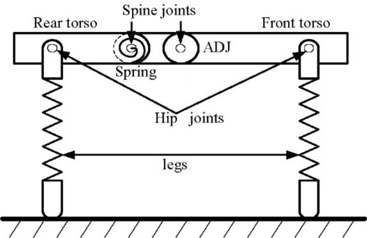
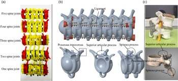
In this paper, we mainly investigate the effect of varying the number of spinal joints in a spine on locomotion speed when the foothold point can be controlled by an ADJ. We designed a model with a spine inspired by a real animal [Reference Boszczyk, Boszczyk and Putz17] to prepare for our following works as shown in Fig. 1. Different from the previous studies, this model has both an ADJ and several passive drive joints within torso. And these passive drive joints are controlled by cable mechanisms during flight phase and gather phase. Legs and hip joints were designed as elastic actuators to simulate the flexibility of animal muscles. The torso was made up of two parts, the front torso and rear torso, connected by ADJ. The rear torso is a series of spinal joints. Fixing the relative motion between the joints can change the number of joints in the spine. By changing the number of spinal joints, the effect of spinal structure on the gait of quadruped running was studied. The contrast tests show that the structure of the spine affects the energy consumption of the robot, increases the stride length of the legs, and increases the acceleration of the robot.
Planar quadruped model with several spine joints near rear torso.

This paper is organized as follows. A close-loop posture control method is proposed in Section 2. Section 3 reports a simulation verification on the relationship between running speed or energy efficiency and joint number. Section 4 relates to a prototype experiment to verify the test result of the simulation experiments. Section 5 discusses the principle of the conclusion in the physics view. Finally, conclusions are presented.
2. Control method
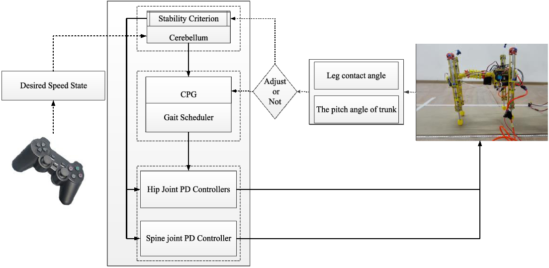
As shown in Fig. 2, the controller consists of three levels, namely low-level control, CPG layer, and policy makers layer, respectively. The cerebellum acts as the policy makers’ layer of controller to deal with those data got from sensors and plan the robot’s locomotion. The data of velocity (v) were measured by an IMU module. The encoder of motor can provide the phase information of robot. Changing the target velocity of robot, the cerebellum also changes the posture of the body to ensure the balance of the robot. The stability criterion is that when the center of gravity reaches its peak, the closer the pitch angle of the trunk is to zero, the more stable the bounding gait will be [Reference Wang, Zhang, Wei, Long and Wang22]. When the displacement of the robot tends to the maximum value in the Z direction and the velocity in the Z direction tends to zero, based on the momentum conservation principle, we can make θ r4 and θf approximately equal by controlling the rotation of ADJ.
Structure of the robot’s controller.

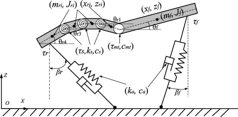
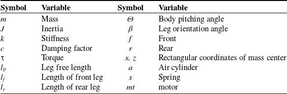
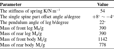
The bionic dynamic model with trunk joints is shown in Fig. 3, and the parameters and state variables applied in the model are shown in Table I. In this paper, the biomimetic dynamic model of the gait of a cheetah is established by using Lagrange’s second type equation, and the equation can be expressed as:
 \begin{equation} \left\{ \begin{array}{l} \dfrac{\textit{ d}}{\textit{ dt}}\dfrac{\partial \textit{ L}}{\partial \dot{\textit{ q}}}-\dfrac{\partial \textit{ L}}{\partial \textit{ q}} = \dfrac{\partial \textit{ P}}{\partial \dot{\textit{ q}}}-\dfrac{\partial \textit{ D}}{\partial \dot{\textit{ q}}}\\[10pt] L = T - V \\[5pt] \textit{ q} = \left[\begin{array}{lll} \textit{ x} & \textit{ z} & \begin{array}{llll} \mathit{\theta }_{\textit{ f}} & \mathit{\theta }_{\textit{ r}\textit{ 1}} & \mathit{\ldots } & \mathit{\theta }_{\textit{ ri}} \end{array} \end{array}\right], i \in (\textit{ 1},\textit{ n}] \\[5pt] \textit{ T} = \dfrac{\textit{ 1}}{\textit{ 2}}\textit{ m}_{\textit{ f}}(\dot{\textit{ x}}_{\textit{ f}}^{\textit{ 2}}\mathit{+}\dot{\textit{ z}}_{\textit{ f}}^{\textit{ 2}})\mathit{+}\dfrac{\textit{ 1}}{\textit{ 2}}\sum\limits_{\textit{ i} = \textit{ 1}}^{\textit{ n}}\textit{ m}_{\textit{ ri}}(\dot{\textit{ x}}_{\textit{ ri}}^{\textit{ 2}}\mathit{+}\dot{\textit{ z}}_{\textit{ ri}}^{\textit{ 2}})\mathit{+}\dfrac{\textit{ 1}}{\textit{ 2}}\textit{ J}_{\textit{ f}}\dot{\mathit{\theta }}_{\textit{ f}}^{\textit{ 2}}\mathit{+}\dfrac{\textit{ 1}}{\textit{ 2}}\sum\limits_{\textit{ i} = \textit{ 1}}^{\textit{ n}}\textit{ J}_{\textit{ ri}}\dot{\mathit{\theta }}_{\textit{ ri}}^{\textit{ 2}}\\[10pt] \textit{ V} = \textit{ k}_{\textit{ a}}(\textit{ l}_{\textit{ 0}}{-}\textit{ l}_{\textit{ f}})^{\textit{ 2}}\mathit{+}\textit{ k}_{\textit{ a}}(\textit{ l}_{\textit{ 0}}\mathit{-}\textit{ l}_{\textit{ r}})^{\textit{ 2}}{+}\dfrac{\textit{ 1}}{\textit{ 2}}\textit{ k}_{\textit{ s}}\sum\limits_{\textit{ i} = \textit{ 2}}^{\textit{ n}}(\mathit{\theta}_{\textit{ ri}}{-}\mathit{\theta }_{\textit{ r}(\textit{ i}{-}\textit{ 1})})^{\textit{ 2}}\mathit{+}\textit{ m}_{\textit{ f}}\textit{ g}\textit{ z}_{\textit{ f}}\mathit{+}\sum\limits_{\textit{ i} = \textit{ 1}}^{\textit{ n}}\textit{ m}_{\textit{ ri}}\textit{ g}\textit{ z}_{\textit{ ri}}\\[5pt] \textit{ P} = \textit{ 2}\mathit{\tau }_{\textit{ f}}(\dot{\mathit{\theta }}_{\textit{ f}}\mathit{-}\dot{\mathit{\beta }}_{\textit{ f}})\mathit{+}\textit{ 2}\mathit{\tau }_{\textit{ r}}(\dot{\mathit{\theta }}_{\textit{ r}\textit{ 4}}\mathit{-}\dot{\mathit{\beta }}_{\textit{ r}})\mathit{+}\mathit{\tau }_{\textit{ mt}}(\dot{\mathit{\theta }}_{\textit{ f}}\mathit{-}\dot{\mathit{\theta }}_{\textit{ r}\textit{ 1}})\mathit{+}\mathit{\tau }_{\textit{ s}}\sum\limits_{\textit{ i} = \textit{ 2}}^{\textit{ n}}(\dot{\mathit{\theta }}_{\textit{ r}(\textit{ i}\mathit{-}\textit{ 1})}\mathit{-}\dot{\mathit{\theta }}_{\textit{ ri}})\\[5pt] \textit{ D} = \textit{ c}_{\textit{ a}}\dot{\textit{ l}}_{\textit{ f}}^{\textit{ 2}}\mathit{+}\textit{ c}_{\textit{ a}}\dot{\textit{ l}}_{\textit{ r}}^{\textit{ 2}}\mathit{+}\dfrac{\textit{ 1}}{\textit{ 2}}\textit{ c}_{\textit{ mt}}(\dot{\mathit{\theta }}_{\textit{ f}}\mathit{-}\dot{\mathit{\theta }}_{\textit{ r}\textit{ 1}})\mathit{+}\dfrac{\textit{ 1}}{\textit{ 2}}\textit{ c}_{\textit{ s}}\sum\limits_{\textit{ i} = \textit{ 2}}^{\textit{ n}}(\mathit{\theta }_{\textit{ ri}}\mathit{-}\mathit{\theta }_{\textit{ r}(\textit{ i}{-}\textit{ 1})})^{\textit{ 2}} \end{array} \right. \end{equation}
where
L – Lagrange function,
q – Generalized coordinates,
T – Kinetic energy of system,
n – Number of spine joints,
V – Potential energy of system,
P – The power of the nonconservative force,
D – Energy dissipation function.
Bionic cheetah dynamic model.

Variables and indexes used in the model.

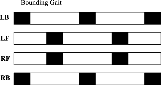
The bounding gait of a quadruped robot is a stable periodic motion in which the front and back legs alternate, like Fig. 4. The periodic motion is controlled by CPG (Central Pattern Generator) in quadruped mammals. Imitating the animals’ biological motion control system, a control strategy (CPG [Reference Spröwitz, Tuleu and Vespignani23]) was proposed to control the robot and the CPG’s advantage has been proved in refs. [Reference Eckert, Spröwitz, Witte and Ijspeert21, Reference Khoramshahi, Spröwitz, Tuleu and Ahmadabadi24, Reference Ijspeert, Crespi and Ryczko25] too. Based on these researches, we choose the CPG as the middle layer of our controller in this paper.
The phase of bounding gaits (black: standing phase, white: swing phase).

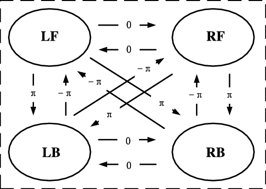
The CPG’s mainly mission is providing the phase transition and the fundamental motion rhythms of legs. Hopf oscillator is a kind of harmonic oscillator with simple structure and easy control, which widely used in quadruped rhythm control. In this paper, we used the Hopf oscillator to build the CPG model of quadruped robot. According to the topological relation between the feet, the topological relation diagram of quadruped robot can be constructed, as shown in Fig. 5. According to the topological relationship, the state equation of Hopf oscillator is constructed as follows:
 \begin{equation} \left\{\begin{array}{l} \beta _{\textit{f}} = \textit{x}_{\textit{1}}\\[5pt] \beta _{\textit{r}} = \textit{x}_{\textit{2}}\\[5pt] \left[\begin{array}{l} \dot{\textit{x}}_{\textit{i}}\\[10pt] \dot{\textit{y}}_{\textit{i}} \end{array}\right] = \left[\begin{array}{c@{\quad}c} \alpha (\mu \mathit{-}\textit{r}_{\textit{i}}^{\textit{2}}) & \mathit{-}\omega _{\textit{i}}\\[5pt] \omega _{\textit{i}} & \alpha (\mu \mathit{-}\textit{r}_{\textit{i}}^{\textit{2}}) \end{array}\right]\left[\begin{array}{l} \textit{x}_{\textit{i}}\\[5pt] \textit{y}_{\textit{i}} \end{array}\right]\mathit{+}\sum\limits_{\textit{j} = \textit{1}}^{\textit{2}}\textit{R}(\varphi _{\textit{i}}^{\textit{j}})\left[\begin{array}{l} \textit{x}_{\textit{i}}\\[5pt] \textit{y}_{\textit{i}} \end{array}\right]\\[10pt] \textit{R}(\varphi _{\textit{i}}^{\textit{j}}) = \left[\begin{array}{l@{\quad}l} \mathit{\cos }\varphi _{\textit{i}}^{\textit{j}} & \mathit{-}\mathit{\sin }\varphi _{\textit{i}}^{\textit{j}}\\[5pt] \mathit{\sin }\varphi _{\textit{i}}^{\textit{j}} & \mathit{\cos }\varphi _{\textit{i}}^{\textit{j}} \end{array}\right]\\[10pt] \varphi _{\textit{i}}^{\textit{j}} = \textit{2}\pi (\varphi _{\textit{i}}\mathit{-}\varphi _{\textit{j}})\\[5pt] \textit{r}_{\textit{i}}^{\textit{2}} = (\textit{x}_{\textit{i}}\mathit{-}\mu _{\textit{1}})^{\textit{2}}\mathit{+}(\textit{y}_{\textit{i}}\mathit{-}\mu _{\textit{2}})^{\textit{2}}\\[5pt] \omega _{\textit{i}} = \dfrac{\omega _{\textit{st}}}{\textit{e}^{\mathit{-}\textit{a}{\textit{y}_{\textit{i}}}}\mathit{+}\textit{1}}\mathit{+}\dfrac{\omega _{\textit{sw}}}{\textit{e}^{\textit{a}{\textit{y}_{\textit{i}}}}\mathit{+}\textit{1}}\\[5pt] \omega _{\textit{st}} = \dfrac{\lambda }{\textit{1}\mathit{-}\lambda }\omega _{\textit{sw}} \end{array}\right. \end{equation}
where
 $\alpha$
– Convergence rate coefficient,
i,j – The serial number of the leg,
 ${\unicode[Times]{x03C6}}$
– The phase of the leg,
 $\sqrt \mu$
– Amplitude,
 $\omega_{\mathrm{st}}$
– Swing frequency of supporting phase,
 $\omega_{\mathrm{sw}}$
– Swing frequency of swing phase,
a – Constant,
λ – The load factor.
The CPG topological structure (LF: left front leg, RF: right front leg, LB: left back leg, RB: right back leg).

The signal for control will be transferred to the low-level controller to keep steady motion and forward speed. The low-level controller’s mission is driving the leg joints and the ADJ according to the signal of angle, which is calculated by the policy makers’ layer or CPG controller. We changed the running speed of the model with the remote controller. The policy makers’ layer calculates the angle of waist bending and the reasonable angle of foot touching the ground according to the target speed and sends the data information to CPG to generate a new control signal.
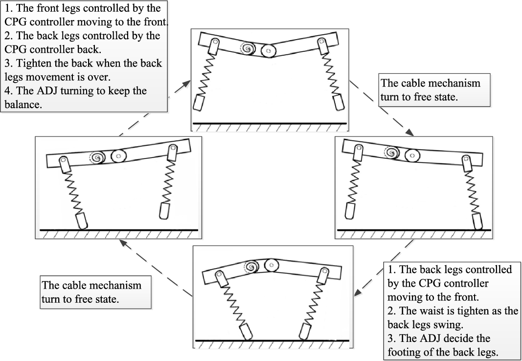
The acceleration process of robot can be divided: leg swing amplitude increase, waist participation, and ADJ participation. The front legs are able to land steadily and maintain balance based on stability criteria, whereas the back legs require additional control due to the participation of the waist. In the first two stages, the waist is transformed from rigid to flexible by controlling the cable mechanism, and the foothold of the back leg is gradually moved forward. In order to avoid the robot toppling backward, we can change the relative position of the back legs and center of gravity by ADJ when the waist is fully contracted. The θ r1 and θf have the same pattern when ADJ rotates, and θf determines the direction of the body’s ejection. In order to keep the robot running stably, we set the following constraints:
 \begin{equation} \left\{\begin{array}{l} \textit{x}_{\textit{cog}}\geq \textit{x}_{\textit{foothold}}\\[5pt] \theta _{\textit{f}}\leq \beta _{\textit{r}} \end{array}\right. \end{equation}
where
xcog – The position of the center of mass in the x direction,
xfoothold – The position of the foothold in the x direction.
The direction of the body’s ejection (θf
) should be less than
 $\beta_{r}$
, so that the robot will not roll over when the back legs push on the floor and the spring in the waist pops open. Meanwhile, the energy stored at the waist allows the robot to fly further. The passive joints driven by cable mechanism are used to store energy, so the waist will be bent as much as possible to store more energy. The control method of the ADJ and the cable mechanism is given in Algorithm 1. And the controls change with the state of the gait stage, as shown in Fig. 6.
The control sequence.


3. The simple structure and simulation
3.1. Model description
Bounding gait provides nature’s quadruped mammals a high-speed motion. And many robots, such as Bobcat-robot [Reference Khoramshahi, Spröwitz, Tuleu and Ahmadabadi24], Scout II [Reference Poulakakis, Smith and Buehler26], MIT Cheetah [Reference Folkertsma, Kim and Stramigioli27], and PAW [Reference Smith, Poulakakis and Trentini28], choosing bounding gait as the main mode of motion in researches have been proved to be advantaged. Therefore, we chose the bounding gait as the motion of the robot.
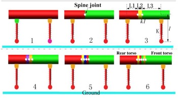
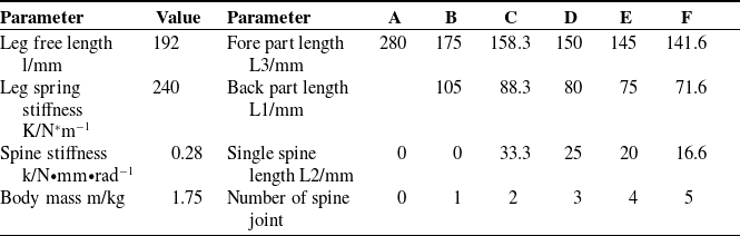
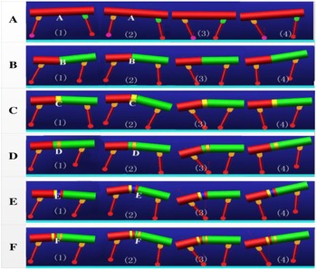
During the movement of bounding, the forelimb, hindlimb, and waist of the quadruped robot can be treated as a planar simplified model with flexible spine [Reference Çulha29]. In order to research the effects of spine joint on the kinematics of quadruped robots in running, we have built several simulation models for comparative experiments, as shown in Fig. 7. Six kinds of planar quadruped models with different spinal structure are introduced. We knew from cheetah skeleton that there are five spinal joints within the waist of cheetah. The first test model has a rigid trunk, and the others have different numbers of spine joints. These spine joints will be distributed at back part trunk, because the rotation position more to the rear could be beneficiary for dynamic robot locomotion [Reference Eckert, Spröwitz, Witte and Ijspeert21]. All models have common characteristics in the structure of leg: two segments with mass, an upper segment and a lower segment. These two leg segments connected by a spring with stiffness and damping ratio. The revolute hip joints connecting body and legs. And the spring within the spinal joints also have damping ratio and stiffness.
Simulation models.

3.2. Simulation environment
Based on these planar simplified test models of quadruped robot, we built a set of tests in Adams and shown it in Fig. 7. The values of these parameters were acquired from the morphology of quadruped mammals and those listed in ref. [Reference Ijspeert, Crespi and Ryczko25]. These test models’ spine stiffness in the simulation environment was set as 0.28 N•mm•rad−1. The relevant researched data about the value of the spine stiffness could be found in refs. [Reference Haueisen30, Reference Herr, Huang and McMahon31]. In the simulation environment, the test model had no spinal movement when the stiffness is set as infinite, but it was free when the stiffness is zero. The effect of flexible spine joint can be imitated by springs and motors. Table II details the relevant parameters of these test models.
Parameters of the simulation model.

The software of MATLAB and Adams provided the simulation environment for these test models. MATLAB acted as the controller of the test model in simulation experiment. The Adams provided the physical environment for running. The static friction coefficient is set to 0.9 in the simulation environment for avoiding feet slippage while running. The length of the ground is infinite.
3.3. Simulations and results
In order to analyze the effects of the different spine structures on the average horizontal speed of test model, the contrastive experiment was carried out in the simulation environment. The contrastive experiment includes six groups. In each group, the experimental model’s spine was bent as far as it could to store more energy. The bending angle range of the torso was set as 0°, +8° to −4°, +16° to −8°, +24° to −12°, +32° to −16°, and +40° to −20°, respectively. We defined the rotation angle of single joint range from +8° to −4° (δ 12 degree), and the contraction is the positive direction, because we measured the limitation of single spine joint rotation is +8.6° ∼ −4.3° from a mammal’s skeleton.
The same gait pattern of the leg for each model was used to avoid the interference of different factors bring. The robot can adjust its stride size autonomously based on the stability criterion. From the simulation, we found the fastest runner is the tested model with five spine joints. Figure 8 presents stable bounding motion of these tested models in one cycle. The bounding gait of the test model in simulation environment had following moments: extended flight moment (snapshot (1) shows), front leg stance moment (snapshot (2) shows), gathered moment (snapshot (3) shows), and back leg stance moment (snapshot (4) shows).
Representative bound-gait snapshots in one cycle (from left to right, respectively). A is the simulation model with stiff spine, B is the simulation model with one spine joint, C is the simulation model with two spine joints, D is the simulation model with three spine joints, E is the simulation model with four spine joints, and F is the simulation model with five spine joints.

After the average horizontal speed of the tested model nearly keep constant, we calculated it’s average speed by the distance per unit time. The mechanical power consumption (P) of every active joint measured directly in Adams. These curves were discretized and turned into discrete vectors. Adding these discrete vectors together, we got a new discrete vector. Then, using MATLAB to fit the curve of the total mechanical power consumption Ptotal
, we got the average value (Pt-average
) from the fitted curve. Comparing the energy efficiency (
 $\varepsilon$
) of each model, we judged which spine structure is better. Then, the
 $\varepsilon$
of the simulation model could be calculated by the following equation:
 \begin{equation} \varepsilon = \frac{\textit{mgv}}{\textit{P}_{\textit{t}\mathit{-}\textit{average}}}, \end{equation}
where
Pt-average – Average power consumption,
m – Total mass,
g – Gravitational acceleration,
v – Average horizontal speed.
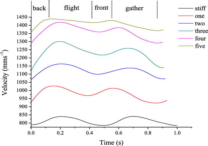
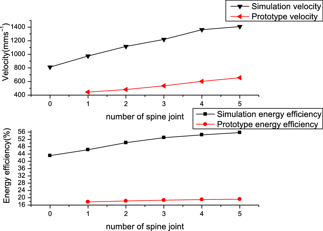
The curves of the tested models’ horizontal speed in simulation environment are shown in Fig. 9. The curves have provided some useful information. Speed curve changes periodically with time and the period of fluctuation decreases gradually with the increase in the joints’ number. Table III details the average horizontal speed of the tested models in simulation environment, the energy efficiency of each model, and the offset angle(α) between fore part trunk and back part trunk. The horizontal speed increases gradually as the number of spine joint ranges from zero to five.
The curves of the horizontal speed of the simulation model in one cycle.

Average horizontal speed and energy efficiency.

In this simulation experiment, the average horizontal speed increases with the number of spine joints. Compared to the model with rigid spine, the average horizontal speed has increased by 20.05%, 37.39%, 50.08%, 67.68%, 73.32%, from one to four spinal joints, respectively. The energy efficiency of the test model with spine joints has increased 7.44%, 16.42%, 22.84%, 26.35%, 29.29% comparing with the model with rigid spine, respectively. Namely, the
 $\varepsilon$
of the test model with spine joints is indeed larger than the one with rigid body. So, it clearly shows that increasing the number of spine joint is benefit for increasing the energy efficiency.
4. Robot and prototype experiment
4.1. Quadruped robot
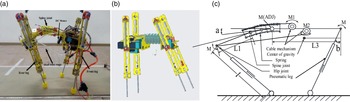
The quadruped prototype robot shown in Fig. 10(a) was designed according to the simplified model. The CAD model of the prototype robot is shown in Fig. 10(b). The mechanical structure of the planar quadruped robot is shown in Fig. 10(c). The prototype robot could be divided into three main parts: a torso, front legs, and back legs.
(a) Robot with rotatory spine DoF, (b) detailed CAD model, and (c) the mechanical structure of the planar quadruped robot.

The torso of the prototype robot was designed based on the real articulated mode of animal trunk. The legs of the prototype robot were designed based on the principle of quadruped mammals’ bounding gait. The leg, driven by pneumatic cylinder, can be treated as an inverted pendulum while the motion of running. The spine joint is a 3D printed part with spherical joint. We designed the structure of spinal joint by the information of quadruped mammal’s skeleton and Ref. [Reference Boszczyk, Boszczyk and Putz17]. The spherical joint enables the trunk can bending, stretching, and twisting as the animal’s torso. The superior articular process and spinous process mainly used to limit the angle of pitch. The structure of the processus transversus provides the room for the spring and attaching the covering structure of the robot’s abdomen. The springs were used to imitate the function of ligament tissue. In order to keep the spine has a certain tension, three springs were used to connect the spinal joints. The springs also can limit the angle of roll. In our previous research [Reference Chen, Li, Wang and Chen16], we have proved the stiffness of the spine influence the horizon speed, and the energy efficiency. The optimal spinal stiffness is influenced by the change in the average horizontal speed. Combining with Khoramshahi M et al [Reference Khoramshahi, Jalaly Bidgoly, Shafiee, Asaei, Ijspeert and Nili Ahmadabadi32]’s research, we have adjusted the stiffness of spring to 54 N/m. The details of the spine are shown in Fig. 11.
(a): The prototype of spine, (b): 3D model of spine, and (c): the model rebuilt from CT scanning image.

The hip joint and the ADJ were actuated by servo motors and the curvature of the spine during the flight moment and the gathered moment was controlled through the cable mechanisms. The function of M1is to simulate the contraction of back muscles when the body is stretched. The function of M2 is to simulate the contraction of abdominal muscles as the body contracts. M1 and M2 work alternately. The torque of the cable mechanism is converted to joint torques, which calculated as Eq. (5). The waist and front torso were hinged and actively driven by a DC motor. When the waist shrinks to the extreme, the DC motor can reverse rotation to adjust the curve of the body and the landing point of the foot.
 \begin{equation} \mathit{\tau }_{\textit{m}} = \mathit{\tau }_{\textit{s}}(\textit{n}\mathit{-}\textit{1}), \end{equation}
where
τ m – The torque of the cable mechanism.
Table IV lists the structure parameters of the robot, and the values of structure parameters are equal proportion to the simulation model.
Parameters of the planar quadruped robot.

4.2. Experiment environment
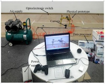
Figure 12 shows the test environment of this experiment. In fast running condition, the musculoskeletal structure of cheetahs’ leg is equivalent to a spring damping system, which can act as a buffer and used to store energy. Air cylinders can provide the same functions. Therefore, it was used to act as the musculoskeletal structure of the robot. Air supply also is necessary for the test. It is important to measure the time consumed of the robot with different spine crossing the same distance, so we designed a test way for the robot. The test way consists of two couple of optoelectronic switches, a camera fixed on a slide way with 1.5 m and a prevent slippery runway.
Environment of the prototype experiment.

In order to record the time, arriving, and leaving, the optoelectronic switch is settled at the middle of the way as the trigger switch. The camera fixed on the slide way is used to take photo for the robot while it running. These data processors start to record the changes of electric current supplied by the power when robot passing the first optoelectronic switch. At last, these data got from data processor and dealt in MATLAB. Using these devices, the horizontal speed of the prototype robot is calculated based on the following equation:
 \begin{equation} \textit{v} = \frac{\textit{s}}{\textit{t}_{\textit{record}}}, \end{equation}
where
v – Horizon speed,
s – Distance between two couple of optoelectronic switches (1.5 m),
trecord – Record time.
The controller of the robot was programmed in the personal computer (PC), and the computer also was used to show the motion. A microprocessor (STM32), installed on the body of the robot, was used to drive RC servo motors and process signals of the incremental photoelectric encoder. A Nvidia Jetson nano was used to deal with the signal from sensors and control the DC motor to adjust the gesture of robot.
The horizontal speed and electrical energy consumption of the robot were directly measured. The power of the robot system was provided by a digital direct current power supply. The data processor can record electric current curve consumed by the robot system and transmit it to the PC via an RS232 interface. The average of electric current (I) was calculated from electric current curve. Air tanks and reducing valves were used to stabilize pressure values in the pneumatic system. We calculated the energy efficiency (
 $\mathit{\eta }$
) of the robot based on following equation:
 \begin{equation} \eta = \frac{mgv}{VI}, \end{equation}
where
VI – Average power of system,
m – Total mass,
g – Gravitational acceleration,
v – Average horizontal speed.
4.3. Experiment and results
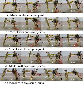
Figure 13 shows the robot’s bounding motion on different phase in the experiment environment. Figure 13(a), (b), (c), (d), and (e) are snapshots of the robot with one spine joint, two spine joints, three spine joints, four spine joints, and five spine joints, respectively. The research method on the bounding gait of the prototype robot was almost same as the method in simulation experiment. In order to eliminate the error brought by the randomness, each kind of spine had been set five groups test experiment.
Stable bounding locomotion of the robot. The bounding gait of the experiment has the following phases: end flight phase (snapshot (1)), front leg stance phase (snapshot (2)), double leg stance phase (snapshot (3)), and rear leg stance phase (snapshot (4)). (a) Model with one spine joint. (b) Model with two spine joints. (c) Model with three spine joints. (d) Model with four spine joints. (e) Model with five spine joints.

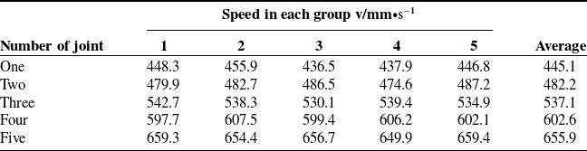
The experimental environment of each group was the same. The values of the average horizontal speed are been listed in Table V arranged according to the number of joints in the spine. As we had got the robot with stiff spine is worse than the robot with spine joint [Reference Chen, Liu, Dong, Wang and Zhang8], therefore, we only compared robots with spinal joints. Obviously, the average horizontal speed of prototype robot is slower than simulation model, and the value of speed increases with the increase in joint’s number.
The value of horizontal speed.

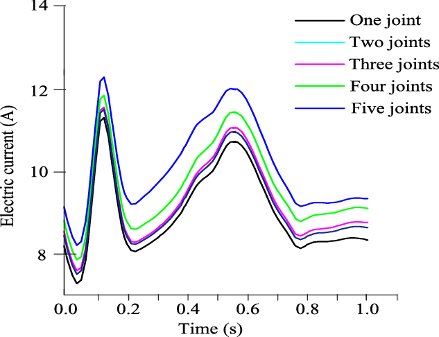
We measured the electric current and recorded the data when the experiment was carried out. The electric current’s expenditure of the robot was measured by the data processor. After the robot enters the test zone steadily, the data processor starts to record the changes of electric current change. These data were downloaded via an RS232 interface and dealt in MATLAB. We obtained a series of discrete data sets by setting the data acquisition frequency. Then, we used the Fourier filter to filter out the noise in these data and plotted a new time-current curve. Figure 14 presents the curve of electric current after processing. The average horizontal speed of the robot has been listed in Table V, and the voltage is 7.4(v) during working. The value of UI is the electrical energy consumption of the whole robot system, which had not included the power consumption of the air compressor. Air cylinder act as the spring damping system of the robot, so the air compressor does not have to work unless the gas tank pressure is less than the minimum pressure. Calculating the Eq. (7) got the value of the robot’s energy efficiency, and the result is listed in Table VI.
The curve of electric current in one cycle.

The result of energy efficiency.

From Table V, we got that the average horizontal speeds of the robot increase with the number of spine joints. Compared to the model with one spine joint, the average horizontal speeds of others model are faster than that, almost 8.34%, 20.67%, 35.39%, 47.36%, from two to five, respectively. However, the average horizontal speeds of robot prototype increase slower than the result of simulation. Table VI presents the average electric and energy efficiency of the robot in the prototype experiment. It reveals that the average electric current of the robot with different spine joints all increase with the increase in joint’s number. The energy efficiency of the prototype robot increases with the increase in the spine joint’s number too. Compared with the energy efficiency of the prototype robot with one spine joint, the others robots are higher than it, almost 2.88%, 5.36%, 7.22%, 8.35%, from two to five, respectively. Obviously, increasing number of spine joints is useful for increasing running speed and energy efficiency. The results of the prototype robot experiment present the same conclusions with the simulation experiment. However, with the increase in the number of spinal joints, the increase rate of energy efficiency gradually slows down, as shown in Fig. 14.
5. Discussion
5.1. Modeling and methodology
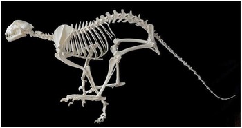
Figure 15 shows the cheetah’s skeleton. The head and tail are used to keep balance while changing posture suddenly. We mainly study the effect of spine in bounding gait. So, the part of head and tail are removed. At the same time, we have highly reconstructed the structure of the spine, the proportions and dimensions of the body.
Cheetah’s skeleton.

The logic behind our step-by-step approach starts with a simple model, but behaviorally analogous to real systems. This simplicity allows us to easily test and analyze our different spines in prototype and simulation robot experiments. More realistic models, such as those presented in refs. [Reference Pouya, Khodabakhsh, Moeckel and Ijspeert15, Reference Eckert, Spröwitz, Witte and Ijspeert21], are uneasy to deal with a detailed study of spine effects. After studying the spinal effects in a simple model, we validated our results by testing them on a prototype robot. From there, we built our hypotheses and we tested that on a quadruped robot in Adams. The simulation results demonstrate our hypothesis that energy efficiency and speed can be increased by changing the spine structure. In addition, we tested our ideas on a real robot; see refs. [Reference Chen, Liu, Dong, Wang and Zhang8, Reference Chen, Li, Wang and Chen16, Reference Chen, Li, Liu, Chen, Wang, Liu and Zhuang33].
5.2. Why joints result in velocity and energy efficiency
The results show that the model with five spine joints has a huge impact on the energy efficiency. Tables III and V show that the effects of five spine joints have increased 44.37% and 47.36% than one spine joint on average horizontal velocity, which indicates the robot with five spine joints can walk with a lager stride and have a better convert system on energy under the same experiment condition.
Considering the influence of structure, we should make a comparison firstly. In fact, we have proved increasing the number of joints can increase the velocity and energy efficiency, Tables V and VI. Compared with the robot with stiff trunk, the robot with spine joints can achieve a larger stride length through the rotation of spinal joints.
Increasing the spine joints continuously, stride length will reach the upper limit, because the robot needs to choose a suitable foothold to keep dynamic balance.
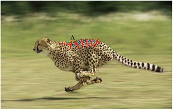
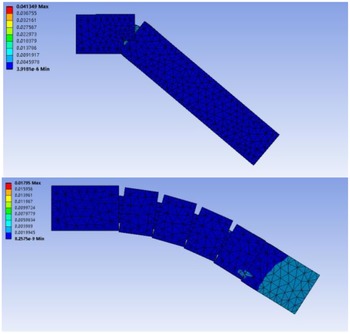
The robot with single spine joint can reach the same stride length when increasing the active range of joint angle. So, why are these animal’s spine conducted by several spine units not one? First of all, we found there is a same characteristic in A point from Figs. 15 and 16. The trunk of the spine is bent down, but the first joint is bent up. Based on this, we added a motor to control the first spine joint in our experiment robot. This motor was used to regulate the gesture of the trunk and the foothold point of the legs when the spine is fully contracted. That is a crucial point (ADJ) for the robot spine structure. The second, we have analyzed the mechanical properties of the two spinal structures through finite element analysis. The spinal structure with one joint is subjected to more stress than the spinal structure with five joints when they are subjected to the same amount of force and bended at the same angle, as shown in Fig. 17, which means the robot with five spine joints can reduce joint strength to reduce overall weight and increase speed. The last, based on the stability criterion and structural model, the maximum bending angle, and landing point of the robot, are relatively fixed. ADJ can adjust the gesture of the robot as well as the foothold point. The additional joints can increase the potential energy by increasing the bending angle and then maintain the balance of the body by ADJ.
Cheetah bounding gait.

Force diagram.

We concluded the result of the energy efficiency from Table VI and Fig. 18. It is indicated that the mechanical structure of the robot has a tremendous influence to the speed. The increase of velocity is really fast with the increase of joint. But, the increase rate of energy efficiency gradually slows down with the increase in the number of spine joints.
The curve of velocity and energy efficiency.

Based on the above analysis, we considered that the robot with ADJ and several spine joints may have greater stride and achieve better energy storage and transfer. The specific reasons are represented as follows:
-
1. Based on the legs being in the supporting moment for the same amount of time, increasing the number of spine joints can increase the degree of curvature of the spine and increase the stride length.
-
2. Increasing the spine joints will increase the stored energy.
-
3. Adding the ADJ will change the foothold and the angle between the body and the ground. The angle decides the magnitude of the support force and forward thrust force. Support force decides the flight time when the total mass of the robot is constant and thrust force decides the speed of the robot flies. When the Angle is small, the robot will get more acceleration, while when the Angle is large, the robot will fly for a short time.
6. Conclusion
In this paper, two sets of tested experiments with a simplified model were carried out, and each simplified model of test robot was different in spine structure within one set of tests. The result of the simulation experiment demonstrates that the increase in the number of joints can indeed affect horizontal velocity. And the energy efficiency indeed increases with the number of spine joint. Judging from the findings of the contrastive test, we found the results of the simulation experiment were verified by prototype experiment. We had explored the relationship between the average horizontal speed, energy efficiency, and the spinal structure. The finding shows we can add an ADJ and increase the number of spine joint in quadruped robot’s spine to get better motion performance. This paper can provide reference for the design of the spine structure of quadruped robot.
-
1. The experiments on the robot demonstrate increasing the number of spine joint can increase the energy efficiency and the average running speed (mobility) on the premise of guaranteeing force equilibrium.
-
2. Increasing the number of spine joints can increase the stored energy.
-
3. The results of the experiments reveal that the ADJ of spine plays an important role, which influences the flight time speed and the acceleration of robot, that may guide the design of robot structure.
Acknowledgments
The authors would like to thank the reviewers and the editor for their constructive remarks and suggestions for improving this paper.