I. INTRODUCTION
The great success in the mobile communication industry has promoted the development of high data rate wireless systems [Reference Sajal1]. Next generation of mobile communication such as long-term evolution (LTE) has been studied and verified for high data rate. Multiple-input multiple-output (MIMO) system has received much attention [Reference Astely2] as one of the most competitive technology for its reliable channel and increased channel capacity. MIMO system can overcome signal fading caused by multipath propagation in complex practical environment. Channel capacity can be increased for the application of multiple antennas. To take full advantage of MIMO system, high isolation between the antenna elements is required, even though they are in a compact portable device [Reference Browne3]. The high mutual coupling between antennas will increase the received signal correlation and decreases channel capacity, which degrades system performance.
To improve isolation between the antenna elements, many effective solutions have been proposed by researchers. Inserting a network between the input ports and antenna ports, decoupling network, proposed by J. BACH ANDERSEN, can reduce the mutual impedance to zero [Reference Andersen4]. However, decoupling network has a limited application in the case that the off-diagonal elements of the admittance matrix are all purely imaginary. The electromagnetic band-gap (EBG) structure is a competitive solution to reduce the mutual coupling for its surface suppressed and wide stopband transmission [Reference Sievenpiper5]. The phase of reflection wave is zero in the operating frequency, which is equivalent to a magnetic wall for an incident wave. However, the size of the EBG structure is too large for the low frequencies, which is not applicable in the compact devices. Other techniques such as neutralization technique [Reference Su6], defected ground structure (DGS) [Reference Li7], and coupling elements [Reference Lau8], may have larger size or long distance between the elements, which are not applicable for limited packages or need special fabrication techniques. Zhang [Reference Zhang9] proposed a two-planar inverted F antenna (PIFA) antenna system with high isolation for wireless local area network (WLAN). Each PIFA is capacitive coupled with a rectangular metal sheet and fed by a 50 Ω SMA coaxial probe. A circular sheet is applied for matching at the end of PIFA. The proposed antenna has a complex structure and is difficult to integrate with printed circuit board (PCB).
In this paper, a compact and high isolation MIMO system for mobile terminal is presented. The system consists of two aperture-coupled shorted patch antenna (ACSPA) with a narrow spacing of only 4 mm. The antenna is fed by an H-shaped slot, which is easily integrated with PCB. Defected shorting wall is used to improve the system isolation. The proposed system features an isolation of better than −20 dB and a maximum isolation of −43 dB at the central frequency. The envelope correlation coefficient (ECC) less than 0.01 is obtained. Good agreement between the simulated and measured results is obtained.
II. MIMO SYSTEM
The configuration of the proposed MIMO structure is shown in Fig. 1. As a basic antenna element, ACSPA is considered for its easy integration with PCB. The system was designed on a low-cost FR4 substrate with a size of 60.5 mm × 43.5 mm. The substrate has a thickness of 0.8 mm and a relatively dielectric constant ε r of 4.4. Two H-shaped slots are removed from the ground plane, and positioned below the patches. The middle arm of each H-shaped slot has a length of 3 mm and a width of 2 mm. The upper and lower sections of the side arm of each H-shaped slot have the same width of 1 mm and lengths S 1 and S 2, respectively. A 50 Ω feed line is printed on the other side of the substrate. The power of electromagnetic wave can be efficiently coupled to the shored patch with the H-shaped slot. The operating frequency approximately corresponds to the length of patch being about one quarter-wavelength [Reference Wong10], which is determined from
Configuration of the proposed MIMO system. (a) Perspective view and (b) defected shorting wall.

 $$f_r = \displaystyle{c \over {4\lpar L_p + H_p \rpar }}\comma \;$$
where f r is the resonant frequency and c is the speed of light.
Defected shorting wall is used to improve the isolation between two antennas. From Fig. 1, it can be seen that a rectangular block is removed from the shorting wall. In order to find the influences on isolation of corresponding structural parameters, a parametric study has been carried out. By altering parameter W b and fixing other parameters, the isolation (S 21) of the proposed MIMO system is shown in Fig. 2(a). It can be seen that when the value of W b equals to zero, the isolation at the WLAN band is −8.2 dB, which is strong coupling between two antennas. The system has poor diversity and no increased channel capacity. The isolation varies with the change of W b. At W b = 3.6 mm, the isolation has a maximum value of −43 dB. Figure 2(b) shows the isolation of proposed system with different values of H b. It is observed that the value of H b has a great impact on the isolation. With different H b, the isolation at WLAN band has a relative large change.
Isolation of the proposed MIMO system versus frequency with different structure parameters. (a) W b and (b) H b.
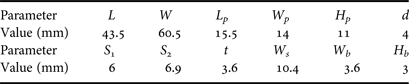
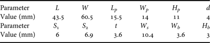
The physical mechanism of defect shorting wall is: the coupling between antennas is caused by the current on ground and the neighboring edges of antenna. With the defect shorting wall, it can form a resonance at the working frequency band, so another coupling path is created. The combined effect of these two paths can cancel each other and the isolation is improved. The current distributions of proposed antenna and traditional antenna were simulated using the Ansoft High-Frequency Structure Simulator (HFSS v13), which are shown in Fig. 3. It can be seen that traditional antenna has a strong coupling due to its small spacing between the elements. When the antenna is fed at port 1, the power can be coupled to the shorted patch and radiate outside. Strong power can be received by the neighboring antenna for their narrow spacing. So there is a high-power output at port 2. However, the proposed antenna with defected shorting wall can change the current distribution on the ground plane. Its effect can cancel the coupling effect, so there is less power output at port 2. With properly chosen values of W b and H b, the proposed system has an optimal performance. The geometrical dimensions of the proposed MIMO system are given in Table 1.
Current distributions of proposed antenna and traditional antenna. (a) Proposed antenna and (b) traditional antenna.
Dimensions of the proposed MIMO system.
III. EXPERIMENTAL RESULTS AND DISCUSSION
To investigate the performance of the proposed MIMO system, a prototype is fabricated and measured. The photograph of the proposed MIMO system is shown in Fig. 4. The simulated and measured S-parameters for our MIMO system are shown in Fig. 5, from where it can be found that the measured results agree well with simulated ones. The proposed structure exhibits an input reflection coefficient (S 11) of less than −10 dB from 2.4 to 2.485 GHz, a mutual coupling lower than −20 dB across the band, and a high isolation (S 21) with a maximum value of −43 dB, which can well satisfy the requirement of MIMO applications. Active devices and radiofrequency (RF) elements can be arranged around the antenna, or on the ground of structure for compact property. The feed line of the proposed MIMO system can be easily connected with other devices mounted on the same substrate. The proposed structure can be installed in the mobile terminal for Bluetooth/WLAN/Wi-Fi system.
Photograph of the proposed MIMO system.
Measured and simulated S parameters. (a) S 11 and (b) S 21.
The simulated and measured radiation patterns of proposed MIMO system are shown in Fig. 6. Figure 6(a) shows the simulated three-dimensional (3D) radiation pattern when port 2 is fed. Unidirectional pattern property and a notch around the x-axis can be observed. The measured and simulated gains are given in Fig. 6(b), which can be seen that there is about 1 dB difference between them. This is due to the loss of connector and test environment. Only measured radiation patterns of one antenna are given for its symmetrical structure. From Figs 6(c) and 6(d), it can be observed that antenna exhibits a unidirectional radiation pattern at 2.4, 2.45, and 2.485 GHz. Every radiation pattern has a notch around the x-axis, which can reduce the mutual coupling between antennas. It also can be seen that xoz-plane pattern is unsymmetrical due to the effect of neighboring element and limited ground plane. When two ports are fed simultaneously with different amplitudes and phases, the far-field radiation patterns can be calculated by the conventional array theory, where the radiations of all elements are summed together.
Simulated and measured radiation patterns of the proposed MIMO system (a) simulated 3D radiation pattern at 2.45 GHz, (b) comparison of simulated and measured gains, (c) measured radiation patterns at yoz-plane, and (d) measured radiation patterns at xoz-plane.
The ECC is a key parameter in MIMO system, which can be used to speculate the diversity of gain and evaluate the capacity of MIMO system. Generally, low ECC means the high isolation between antennas, and will lead to high diversity gain. This parameter cannot be obtained with directly test, but it can be calculated with the radiation pattern or the S parameters [Reference Blanch11].
From S-parameter theory in the network, the total power entering the antenna system is calculated by
 $$P_{in} = a_1^2 + a_2^2 - b_1^2 - b_2^2 = a^H \left({I_2 - S^H S} \right)a\comma \;$$
where I 2 is the 2*2 identity matrix, and S is the scattering matrix. Meanwhile, the total radiated power by the MIMO antenna system is expressed as
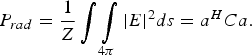 $$P_{rad} = \displaystyle{1 \over Z}\vint\int\limits_{4\pi} {\left\vert E \right\vert ^2} ds = a^H Ca.$$
According to the conservation of energy, the input power is equal to the radiation power when the network is lossless. With equations (2) and (3), it follows that C = I 2 − S HS. Therefore, a simple formulation of the ECC derived from the S parameters can be expressed as:
 $$\rho _e = \displaystyle{{C_{12} \bullet C_{21} } \over {C_{11} \bullet C_{22} }} = \displaystyle{{\left\vert {S_{11}^\ast S_{12} + S_{21}^\ast S_{22} } \right\vert ^2 } \over {\left({1 - \left\vert {S_{11} } \right\vert ^2 - \left\vert {S_{21} } \right\vert ^2 } \right)\left({1 - \left\vert {S_{22} } \right\vert ^2 - \left\vert {S_{12} } \right\vert ^2 } \right)}}.$$
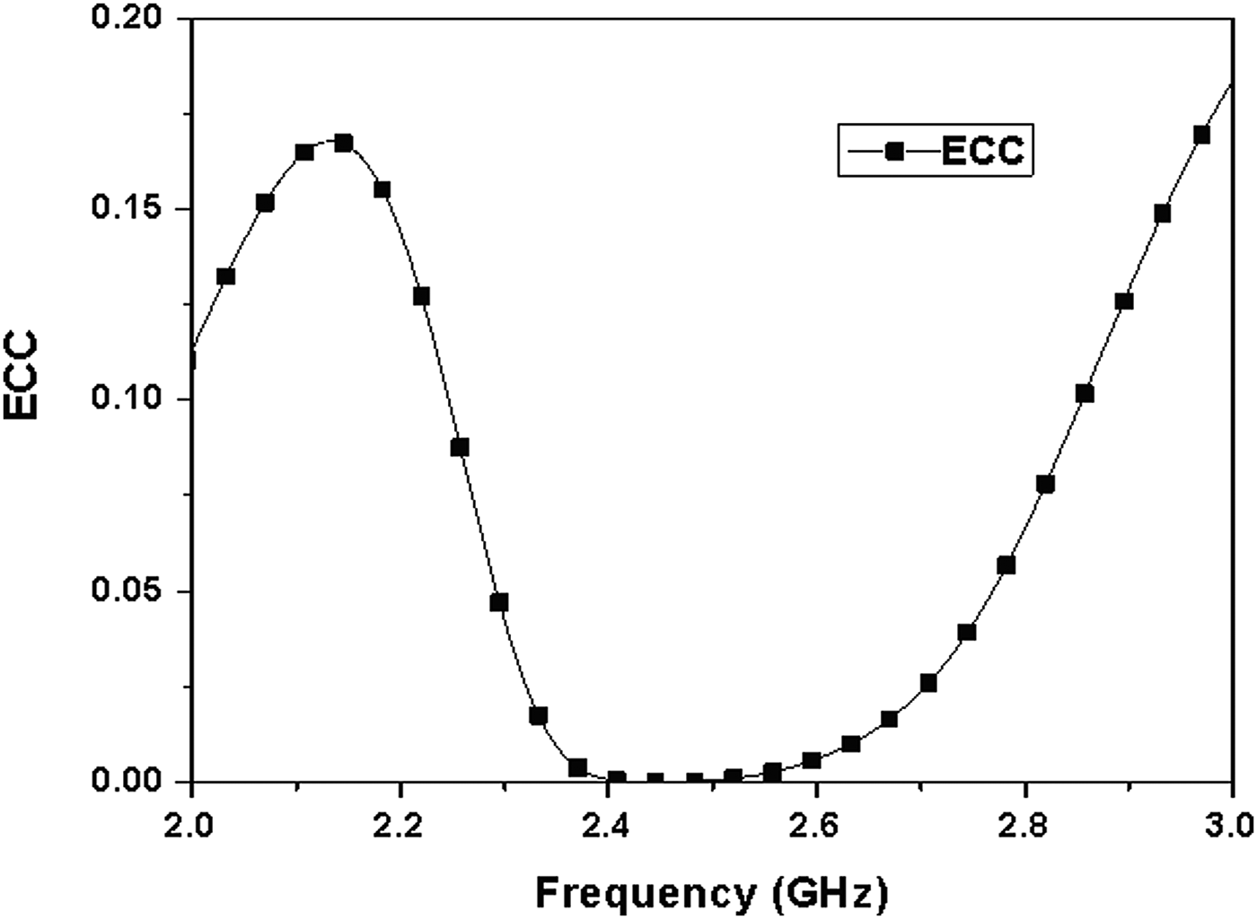
The proposed antenna has a radiation efficiency of 92% at 2.45 GHz. ECC of the proposed MIMO system is calculated with S parameters and plotted in Fig. 7. The calculated results show that the proposed antenna array has the envelope correlation efficiency less than 0.01 at the desired operation band, which is very suitable for MIMO application.
ECC of the proposed MIMO system.
IV. CONCLUSION
A compact MIMO antenna system with high isolation has been designed and analyzed. ACSPA is used as the basic element of structure, which can cover the operating band from 2.4 to 2.485 GHz. Two antennas are closely placed with a spacing of only 4 mm, and defected shorting wall is used to improve the isolation. This structure is easy to be integrated with planar circuits. An isolation of better than −20 dB and a maximum isolation of −43 dB are achieved for the proposed MIMO system. The measured radiation patterns and computed ECC are given. This antenna array has a good potential for MIMO application for its compact structure, high isolation, and low ECC.
ACKNOWLEDGEMENTS
This work is supported partly by the Program for New Century Excellent Talents in University of China, and partly by the National Natural Science Foundation of China under Contract nos. 61072017 and 61101066. Natural Science Basic Research Plan in Shaanxi Province of China (no. 2013JZ019), National Key Laboratory Foundation, and Fundamental Research Funds for the Central Universities (K5051202051, K50511020033, K50511020006, and K5051302030).
Xi-Wang Dai was born in Caoxian, Shandong, China. He received the B.S. and M.S. degrees in Electronic Engineering from Xidian University, Xi'an, Shannxi, China, in 2005 and 2008, respectively. From March 2008 to August 2011, he worked at Guangdong Huisu Corporation as a manager of Antenna Department. Now, he is pursuing the Ph.D. degree in electromagnetic fields and microwave technology at Xidian University. His current research interests involve metamaterials, omni-directional antenna, MIMO antenna, and low-profile antenna.
Long Li (M'06) was born in Guizhou, China. He received the B.E. and Ph.D. degrees in electromagnetic fields and microwave technology from Xidian University, Xi'an, China, in 1998 and 2005, respectively. He joined the School of Electronic Engineering, Xidian University, in 2005 and was promoted to Associate Professor in 2006. He was a Senior Research Associate in the Wireless Communications Research Center, City University of Hong Kong, in 2006. He received the Japan Society for Promotion of Science (JSPS) Postdoctoral Fellowship and visited Tohoku University, Sendai, Japan, as a JSPS Fellow from November 2006 to 2008. He is currently a Professor in the School of Electronic Engineering, Xidian University. His research interests include computational electromagnetics, electromagnetic compatibility, and novel artificial metamaterials.
Zhen-Ye Wang was born in Caoxian, Shandong, China. She received the Bachelor degree from Northeast Forestry University, Harbin, China, in 2006. She received the Master degree from Shaanxi Normal University, Xi'an, China, in 2011. From August 2011, she is working at Huisu Corporation as an antenna engineer. Her research interests include computational electromagnetics and antenna array.
Chang-Hong Liang graduated from North-West Telecommunication Engineering Institute, now Xidian University, Xi'an, China, in 1965. Since 1967, he has been with the Department of Electromagnetic Engineering, Xidian University, where he is now a Professor. From 1980 to 1982, he was a Visiting Scholar at Syracuse University, Syracuse, NY. His main interests include computational electromagnetics, computational microwave, network theory, electromagnetic scattering and inverse scattering, and electromagnetics soliton. In these areas, he has published ten books and over 200 journals and international conference papers.