I. INTRODUCTION
Nowadays, due to a growing concern for the air pollution produced by diesel/gasoline powered cars, there is a relevant interest in the development of electric vehicles (EVs). They are equipped with large batteries that must efficiently and rapidly be recharged. These batteries can be charged either from an external source of electricity, i.e., by a physical plugged connection, or by a wireless power transfer (WPT) technology. To increase comfort and electrical safety in the charging process, the WPT recharge, based on resonant inductive coupling, is currently under investigation by car manufacturers, electricity boards, and road transportation planners [Reference Covic and Boys1, Reference Shinohara2]. In particular, for automotive applications, there are still some problems to be addressed [Reference Kim, Park, Kim, Kim and Ahn3, Reference Kim4]. One of the main concerns is the compliance of the emitted magnetic field with the electromagnetic field's (EMF) safety standards and regulations [5–8]. The safety guidelines specify some limits in terms of reference levels (measurable fields in air without the presence of the exposed human body) and basic restrictions (electromagnetic quantities inside the human body) to protect the humans against short-term or acute effects. For the application under investigation, the main problem consists in the magnetic field levels produced by the WPT coil currents that must be below the reference levels. Indeed, the EMF safety guidelines provide basic restrictions, which are directly related to acute effects, but probably also the exceedance of the reference levels could cause big concerns in the public opinion, also because the precaution principle is not applied in the safety standards to protect the general public against possible long-term effects. Thus, it is relevant for car industries that their products comply with the reference levels to prevent any public alarm that could slow down the development and production of EVs.
The present study deals with the numerical characterization of the magnetic field inside and around an electric car equipped with a WPT system. The computed magnetic field levels are compared with the EMF safety limits to assess the compliance. Previous authors working in this field made considerable simplified assumptions (i.e. perfect electric conductive conditions for the car body) [Reference Laakso and Hirata9, Reference Shimamoto, Laakso and Hirata10], and therefore the evaluation of the magnetic field penetration through the metallic chassis was not considered. In this study, the field inside an EV is evaluated numerically by an accurate model of the car body made by three different materials: steel, aluminum, and carbon-fiber composite. Some numerical techniques are also revised to model accurately the magnetic field penetration through thin metallic shields.
II. MATHEMATICAL MODEL
A) Thin layer modeling in near field domain
The magnetic field produced by a WPT recharging system of EV batteries can be described in frequency domain by the eddy currents equations since the displacement currents are negligible at the relatively low-frequency range used for this kind of application (10–150 kHz). Using a traditional mesh approach in a finite element method (FEM) analysis, the car body must be finely discretized to accurately evaluate the field penetration inside the conductive domains. Normally, the finite element size h must be much lower than the penetration depth δ at the considered frequency (h ≪ δ). This very fine discretization leads to a great number of unknowns and, therefore, to large memory storage and computational time. At higher frequencies, when the penetration depth tends to be very small, the spatial discretization inside the conductive region is impracticable. Thus, in order to reduce the computational cost, conductive domains are sometimes roughly discretized by inexperienced researchers and the accuracy can be very bad. This problem can be overcome by using alternative methods based on the elimination of the conductive region from the computational domain and the introduction of equivalent boundary conditions on the new boundary surfaces created by the elimination. Adopting this procedure, there are several options for modeling metallic sheets. Here, the exact impedance network boundary conditions (INBCs) [Reference Feliziani, Maradei and Tribellini11–Reference Feliziani15] are compared with the approximate transition boundary conditions (TBCs) of COMSOL 3.5 [16]. The INBCs can be considered exact for high-conductivity materials as metals embedded in dielectric regions [Reference Feliziani, Maradei and Tribellini11].
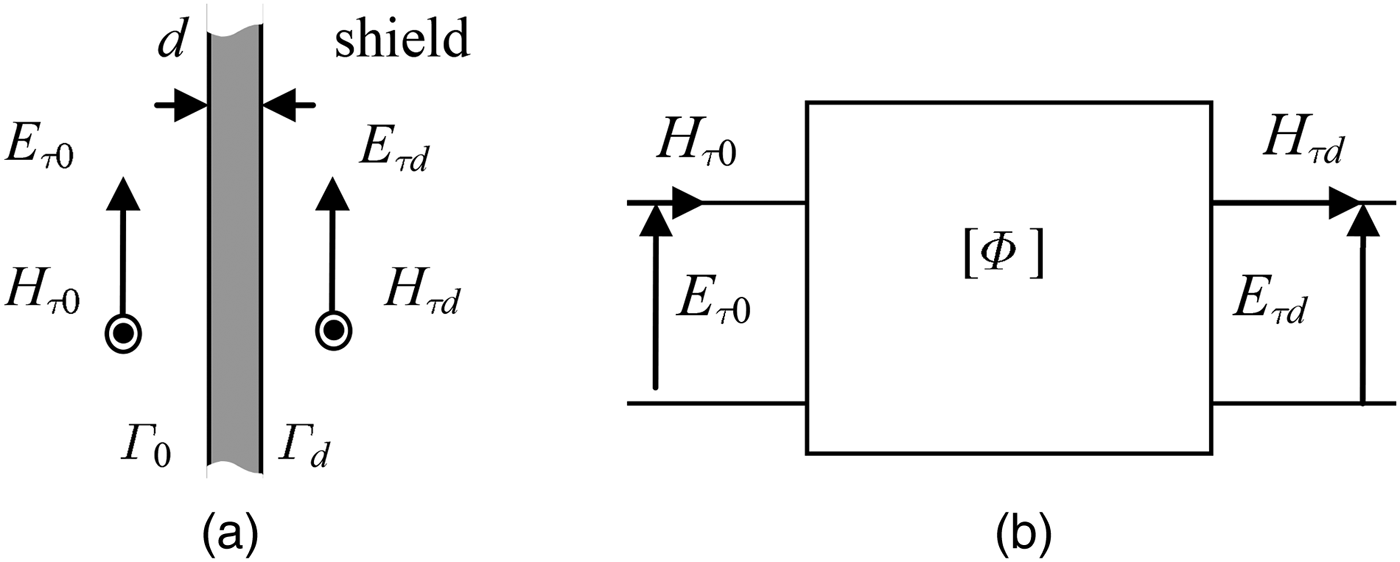
The field penetration inside a thin conductive metal panel, as the car platform, is governed by the plane wave equations [Reference Feliziani, Maradei and Tribellini11]. The propagation in a solid planar panel (see Fig. 1) of thickness d, permittivity ε, permeability μ, conductivity σ, is described by the transmission line equations:
 $$\left[ {\matrix{ {E_{\tau 0}} \cr {H_{\tau 0}} \cr}} \right] = \left[ \Phi \right]{\rm} \left[ {\matrix{ {E_{\tau d}} \cr {H_{\tau d}} \cr}} \right],$$
where E τ0, E τ d , H τ0, H τ d are the field components tangential to the two shield faces (Γ 0, Γ d ), and [Φ] is the panel chain matrix given by
 $$\left[ \Phi \right] = \left[ {\matrix{ {\cosh (\gamma d)} & {\eta \sinh (\gamma d)} \cr {\sinh (\gamma d)/\eta} & {\cosh (\gamma d)} \cr}} \right]{\rm} {\rm.} $$
Field penetration of a thin conductive panel: (a) configuration of a solid planar sheet and (b) equivalent two-port network.

In (2), η and γ are the intrinsic impedance and the propagation constant, respectively, given for good conductors by
 $$\eta \cong \sqrt {j\omega \mu /\sigma} {\rm,} $$
 $$\gamma \cong \sqrt {j\omega \mu \sigma} {\rm} {\rm.} $$
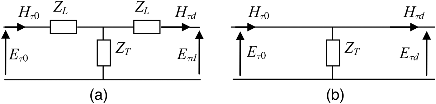
Equation (1) with [Φ] given by (2) is known as INBC and was successfully implemented in numerical differential methods [Reference Feliziani, Maradei and Tribellini11–Reference Feliziani15]. In one-dimensional (1D) domain, the INBC can exactly be modeled by a T-circuit, as shown in Fig. 2(a), composed of two identical longitudinal impedances Z L and a transversal impedance Z T given by:
 $$Z_L = \eta \displaystyle{{\cosh (\gamma d) - 1} \over {\sinh (\gamma d)}},$$
 $$Z_T = \displaystyle{\eta \over {\sinh (\gamma d)}}.$$
Equivalent two-port networks for a 1D domain: (a) INBC and (b) TBC.

When the argument of the hyperbolic functions in (2) is small, i.e. |γ d| ≪ 1, approximate expressions of hyperbolic functions can be used and the chain matrix [Φ] becomes:
 $$\left[ \Phi \right] \cong \left[ {\matrix{ 1 & {j\omega \mu d} \cr {\sigma d} & 1 \cr}} \right],$$
which is known as thin layer approximation. For many practical cases, (6) can be approximated by:
 $$\left[ \Phi \right]{\rm} \approx \left[ {\matrix{ 1 & 0 \cr {1/R_s} & 1 \cr}} \right]{\rm,} $$
where R s is the sheet resistance defined as:
 $$R_s = \displaystyle{1 \over {\sigma d}}.$$
The 1D equivalent circuit reduces to only the shunt impedance Z T = R s . Equation (1) with [Φ] given by (7) via (8) is modeled in commercial softwares as COMSOL 3.5, where it is known as TBC. As can be seen from the above derivation, TBC can be considered an approximation of the INBC.
Both INBC and TBC can be implemented in differential numerical methods, such as the FEM. From a computational viewpoint, the number of degrees of freedom on the internal boundary is doubled in both INBC and TBC to compute the tangential fields on sheet surface. However, in terms of implementation, the electromagnetic constraint includes only the field variables on both sheet surfaces in the TBC, while using the INBC, all the variables of the two finite elements adjacent to both sheet sides are included [Reference Buccella, Feliziani, Maradei and Manzi14]. It means that the TBC implementation is much easier than that of the INBC. Furthermore, the TBC implementation is available in commercial software tools [16] and, therefore, it is very convenient to be used, when possible. Thus, it is very relevant to evaluate the accuracy of the TBC for WPT automotive applications. Both INBC and TBC can predict the reflected and transmitted fields. Table 1 summarizes the main characteristics of INBC and TBC.
Main characteristics of INBC and TBC applied to a FEM code.

B) Method validation
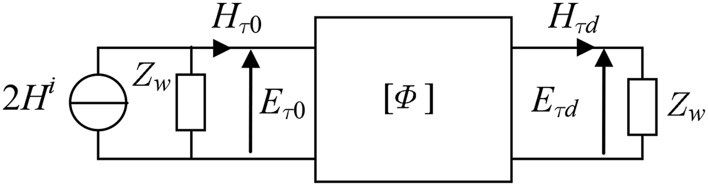
The different boundary conditions are validated in 1D domain by analyzing the equivalent circuit shown in Fig. 3. In the circuit, Hi is the unitary incident magnetic field and Z w is the near field wave impedance given for a low-frequency magnetic field point source by:
 $$Z_w \cong j\omega \mu _0 d_s, $$
where d s is the distance between the source and the observation point.
Equivalent circuit for coupled tangential fields on the sheet surfaces for a 1D domain.

A parametric investigation by circuit analysis is performed to compare INBC and TBC techniques, considering the following variables:
-
- different material (aluminum and steel);
-
- different thickness (d = 2 mm and d = 1.2 mm);
-
- variable distance from the source (d s = 1 cm and d s = 10 cm);
-
- variable frequency (f = 85 kHz and f = 150 kHz).
The results, reported in Tables 2–5, show that the magnetic field error in the TBC solution is higher for d s = 1 cm than for d s = 10 cm. For higher distance d s from the source, the TBC solution is a satisfactory approximation of the exact INBC solution. On the other side, the electric field error is higher than that exhibited by the magnetic field, but acceptable for this kind of application as the magnetic field is much more relevant. The TBC accuracy increases as the wave impedance Z w increases. Finally, it should be noted that (9) is valid for a point magnetic source (i.e. small loop), while for WPT coils, Z w can be very different due to the complexity of the source. Thus, a numerical investigation is proposed in the following.
Tangential fields (magnitude and phase in radians) calculated for an aluminum sheet of thickness d = 2 mm calculated assuming d s = 1 cm and d s = 10 cm, with INBC and TBC at f = 85 kHz.

Tangential fields (magnitude and phase in radians) calculated for an aluminum sheet of thickness d = 2 mm calculated assuming d s = 1 cm and d s = 10 cm, with INBC and TBC at f = 150 kHz.

Tangential fields (magnitude and phase in radians) calculated for a steel sheet of thickness d = 1.2 mm calculated assuming d s = 1 cm and d s = 10 cm, with INBC and TBC at f = 85 kHz.

Tangential fields (magnitude and phase in radians) calculated for a steel sheet of thickness d = 1.2 mm calculated assuming d s = 1 cm and d s = 10 cm with INBC and TBC at f = 150 kHz.

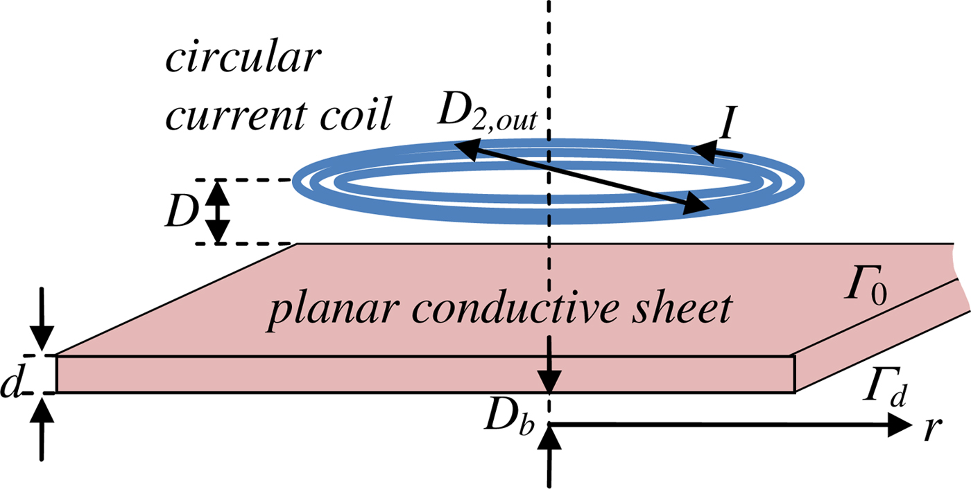
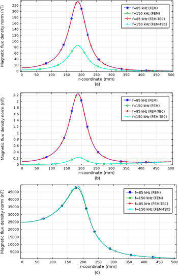
In order to test the accuracy of the TBC for WPT automotive applications, a simple 3D FEM analysis has been performed considering three materials: steel, aluminum, and carbon-fiber composite. This last material is multi-ply with different fiber orientation but it has been assumed to be isotropic and homogeneous [Reference Holloway, Sarto and Johansson17]. The numerical test configuration is given by a unitary time-harmonic current flowing into a circular coil that excites a planar sheet (steel: σ = 1 × 10⁷ S/m, d = 1.2 mm; aluminum alloy: σ = 3 × 10⁷ S/m, d = 2 mm; composite: σ = 100 S/m, d = 2 mm) modeled by standard FEM or by using the FEM with TBC. In the first case, the sheet is fully discretized by finite elements, while in the second case, the sheet is eliminated and replaced by TBC to couple the two sheet surfaces. The source is a planar circular coil with N 2 = 8 turns and D 2,out = 400 mm outer diameter having a distance D = 25 mm between the sheet and the coils, as shown in Fig. 4. Two frequencies (85 and 150 kHz) are analyzed and the magnetic field is calculated along the radial axis r at a distance D b = 10 mm behind the sheet. The results depicted in Fig. 5 show the accuracy of the TBC approximation for this frequency range and for the considered materials. As you can see, the TBC is a very suitable technique to model the magnetic field inside an EV in the frequency range of the WPT application. Finally, it should be noted that the values of the panel thickness and conductivity are selected as low as possible to obtain the worst case scenario.
Configuration of a coil current above a metallic plate.

Magnetic flux density calculated along r-axis (see Fig. 4) by fully discretized FEM and by FEM with TBC for steel (a), aluminum (b), and composite (c) sheets excited by a unitary coil current.

III. APPLICATION
A) System configuration
At the present time, several standards for WPT application in EVs have been established [18]. The most relevant characteristics are the transfer power and the operational frequency. For a medium size car, the transfer power is set to 7.7 kW and the operational frequency is set to 85 kHz. For the future development of standard, an increasing of the operational frequency will be considered to improve system performances.
In this work, two WPT systems with operational frequencies of f = 85 kHz and f = 150 kHz have been considered. The parameters of the circuits are optimized to transfer efficiently to load a power of P L = 7.7 kW with output voltage V 2 = 200 V [Reference Campi, Cruciani, De Santis, Palandrani, Hirata and Feliziani19]. For simplicity, the load is modeled as a simple power resistor, while the source is modeled as an ideal sinusoidal voltage generator [Reference Cruciani, Campi, Maradei and Feliziani20].
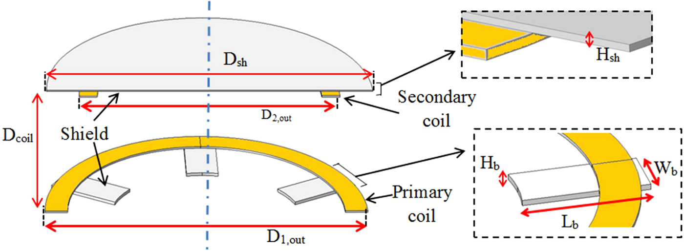
The WPT is composed of two planar circular coils, and the distance between the stacked primary and secondary coils is set to D coil = 20 cm as shown in Fig. 6. The configuration of the coils in terms of number of turns and outer diameter is given by:
-
• Primary coil: N 1 = 10, D 1,out = 500 mm.
-
• Secondary coil: N 2 = 8, D 2,out = 400 mm.
Configuration of the WPT coil system (primary coil on the road and secondary on the car platform).

The coils are realized using Litz wire to reduce a.c. losses. The wire is composed of 1050 strands of 38 AWG copper wires equivalent to a geometrical diameter of about 4.5 mm, able to avoid the skin effect at the considered frequencies. Ferrites are introduced in the WPT coil configuration to shield the magnetic field and to improve the electrical performances [Reference Feliziani21]. In proximity of the primary coil, n b = 6 ferrite bars of dimensions l b = 9.3 cm, w b = 5.8 cm, h b = 0.4 cm are radially arranged with respect to the center of each coil, while a cylindrical disk of ferrite with diameter D sh = 50 cm and thickness H sh = 2 mm has been placed over the secondary coil at distance D m = 8 mm from the car platform filled by a plastic support. The ferrite has relative magnetic permeability μ r = 2400 and negligible conductivity. The car platform is considered as a metal plate parallel to the secondary coil. The metal plate has a thickness d = 2 mm and conductivity σ = 3·107 S/m.
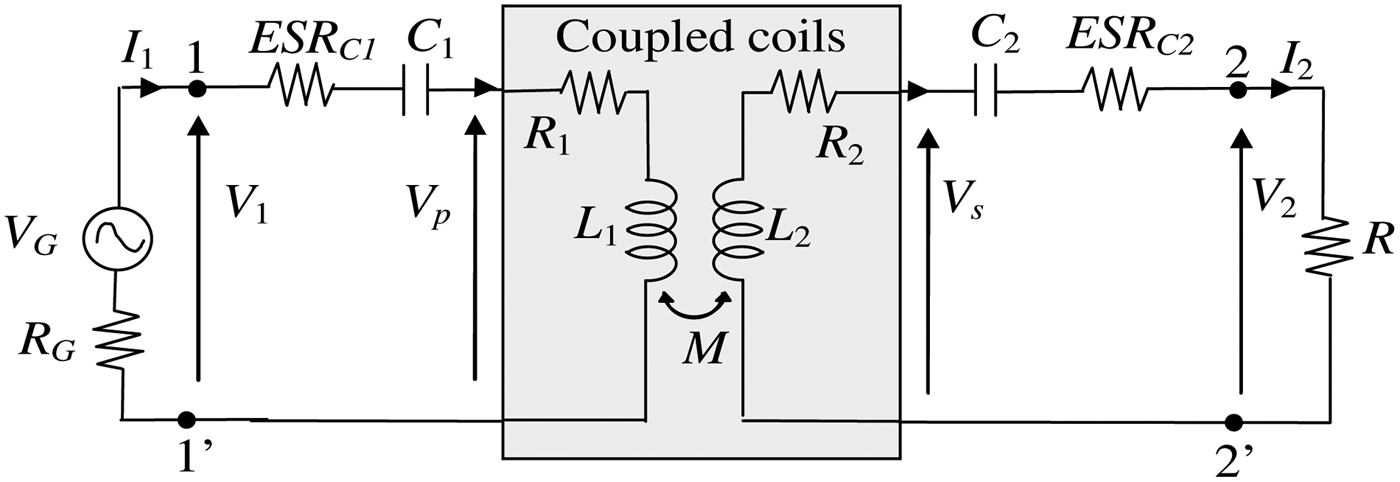
The WPT system is modeled by the equivalent circuit shown in Fig. 7. First, a FEM simulation is carried out to extract numerically the self and mutual inductances of the coils: L 1, L 2, and M [Reference Campi, Cruciani, De Santis, Palandrani, Hirata and Feliziani19]. Due to the geometrical complexity, the a.c. resistances of the Litz wire coils are obtained from datasheets and have values R 1 = 80 mΩ and R 2 = 55 mΩ for both considered frequencies. In all test cases, a series–series (SS) compensation topology is adopted for the WPT system. In the simulations, the capacitors losses of the compensation network are considered introducing an equivalent series resistance (ESR) (i.e. ESR C1 = ESR C2 = 20 mΩ). Several circuit simulations have been performed to predict the electrical performance of the system in terms of efficiency and coils currents, and the results are successively used to calculate the magnetic field emission [Reference Cruciani, Maradei and Feliziani22].
WPT equivalent circuit with SS compensation topology.

The lumped parameters, compensation capacitors, efficiency, and coils currents of the systems are evaluated for the two considered frequencies. First, the coils are assumed to be in air, while in the second simulation, the presence of the car body is considered. The metal plate negatively alters the coupling between the coils reducing the efficiency, and consequently increasing the currents and the emitted magnetic field. This negative effect of the metal sheet is only partially mitigated by the presence of the ferrite [Reference Cruciani and Feliziani23–Reference Campi, Cruciani, Maradei and Feliziani26]. The obtained numerical results are reported in Table 6 for coils in air and in Table 7 for the case with the presence of the metallic plate. The efficiency in the two considered cases is quite similar. It should be noted that for the considered compensation topology, the currents I 1 and I 2 are in quadrature. This aspect is very important for the characterization and the mitigation of the magnetic field. In all simulations, the temperature of the components is set to T c = 25 °C; however, small changes in temperature do not significantly alter the obtained results in terms of electrical performances and magnetic field.
WPT lumped inductances, compensation capacitors, r.m.s. currents and efficiency with coils in air.

WPT lumped inductances, compensation capacitors, r.m.s. currents and efficiency with coils under the metallic car platform.

B) EV configuration
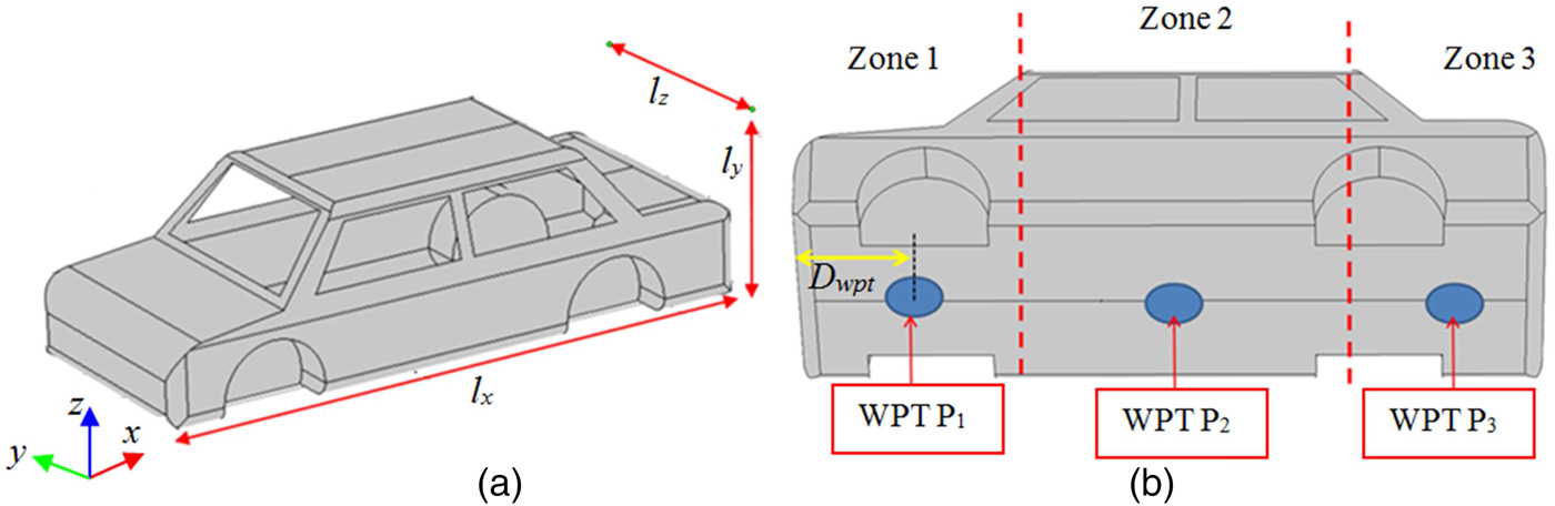
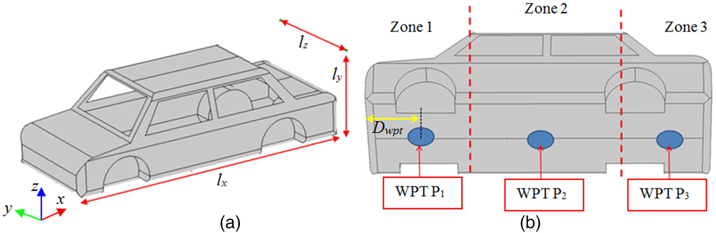
To predict the magnetic field distribution inside and outside the vehicle, a 3D model suitable for FEM analysis has been realized. The car outer dimensions are: l x = 4.3 m, l y = 1.7 m, and l z = 1.2 m (without wheels). The distance between anterior and posterior wheel axes is 2.6 m. The distance of the car platform from the ground (when the wheels are in place) is set to 20 cm. The whole vehicle body is modeled in COMSOL by homogeneous sheet panels as shown in Fig. 8. The thickness of the panel d and its material conductivity σ is assumed to be different for the three test cases to reproduce carbon-fiber composite, aluminum, and iron chassis cars. In the simulations, the test cases are carried out with the following characteristics:
-
(1) Composite panels (d = 2 mm, σ = 100 S/m).
-
(2) Steel panels (d = 1.2 mm, σ = 1 × 10⁷ S/m).
-
(3) Aluminum alloy panels (d = 2 mm, σ = 3 × 10⁷ S/m).
A 3D model of the car in COMSOL (a). Three different positions for the WPT coil system on the bottom of the bodywork of the car (b).
C) Calculated magnetic field levels
The magnetic field distribution has been calculated for two frequencies and three different materials. The WPT receiving coil is assumed to be located in the car underbody in three different positions, as shown in Fig. 7(b). In the first position the coil center P 1 is placed at distance D wpt = 1 m from the front of the vehicle; in the second position P 2 is at distance D wpt = 2.3 m; and in the last position P 3 is at distance D wpt = 3.7 m. The excitation currents are different for composite and conductive material chassis. In the first, the currents are assumed to be equal to the case of coils in air reported in Table 6, while for the conductive material chassis, the currents are considered equal to those reported in Table 7.
The maximum value of the r.m.s. magnetic field B max inside the vehicle has been calculated by a FEM analysis in three different zones (front, body, and rear) of the car, and the obtained results are reported in Table 8 at f = 85 kHz and in Table 9 at f = 150 kHz, respectively.
Maximum r.m.s. magnetic flux density B max (T) at 85 kHz inside the car.

Maximum r.m.s. magnetic flux density B max (T) at 150 kHz inside the car.

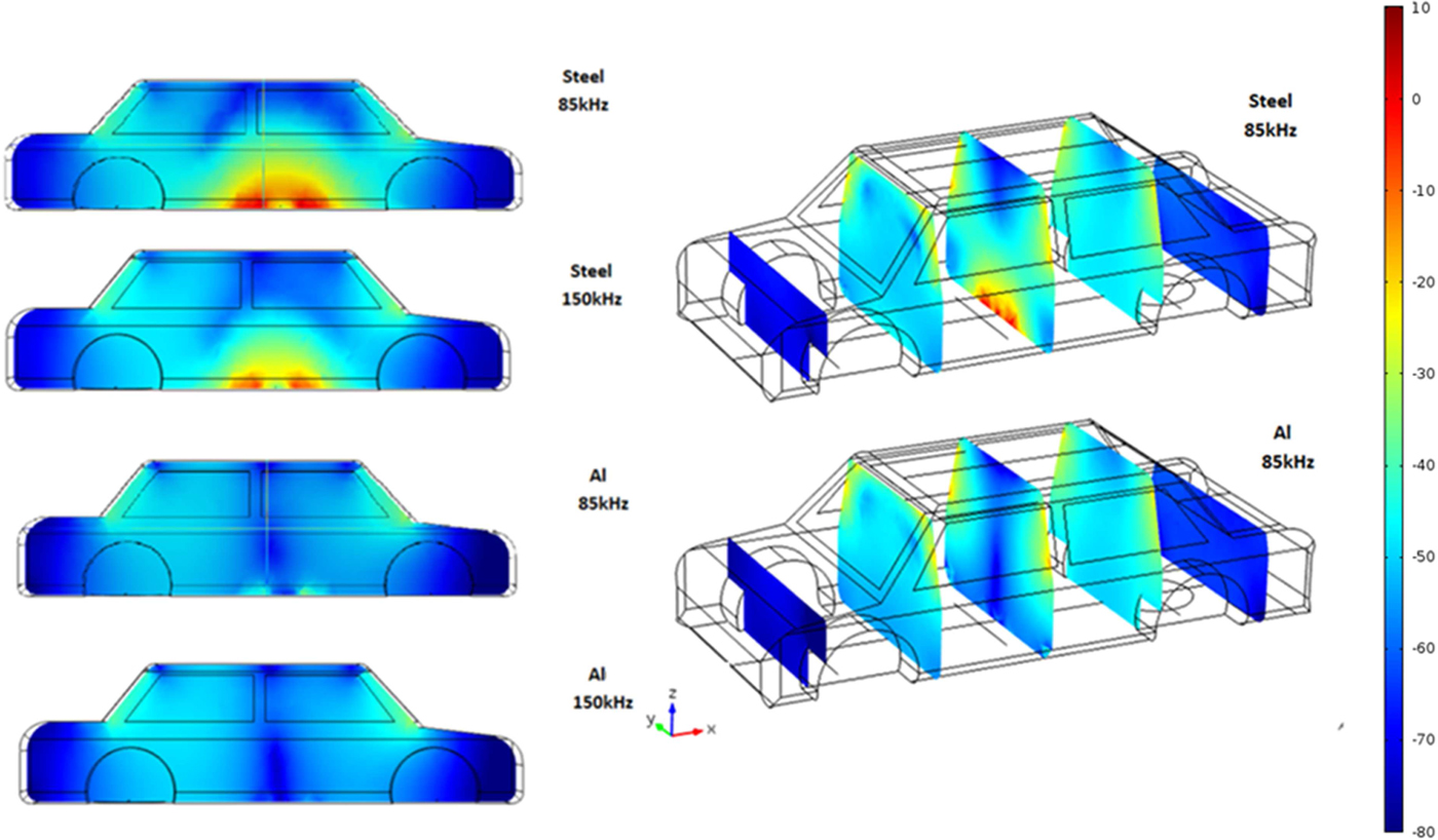
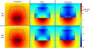
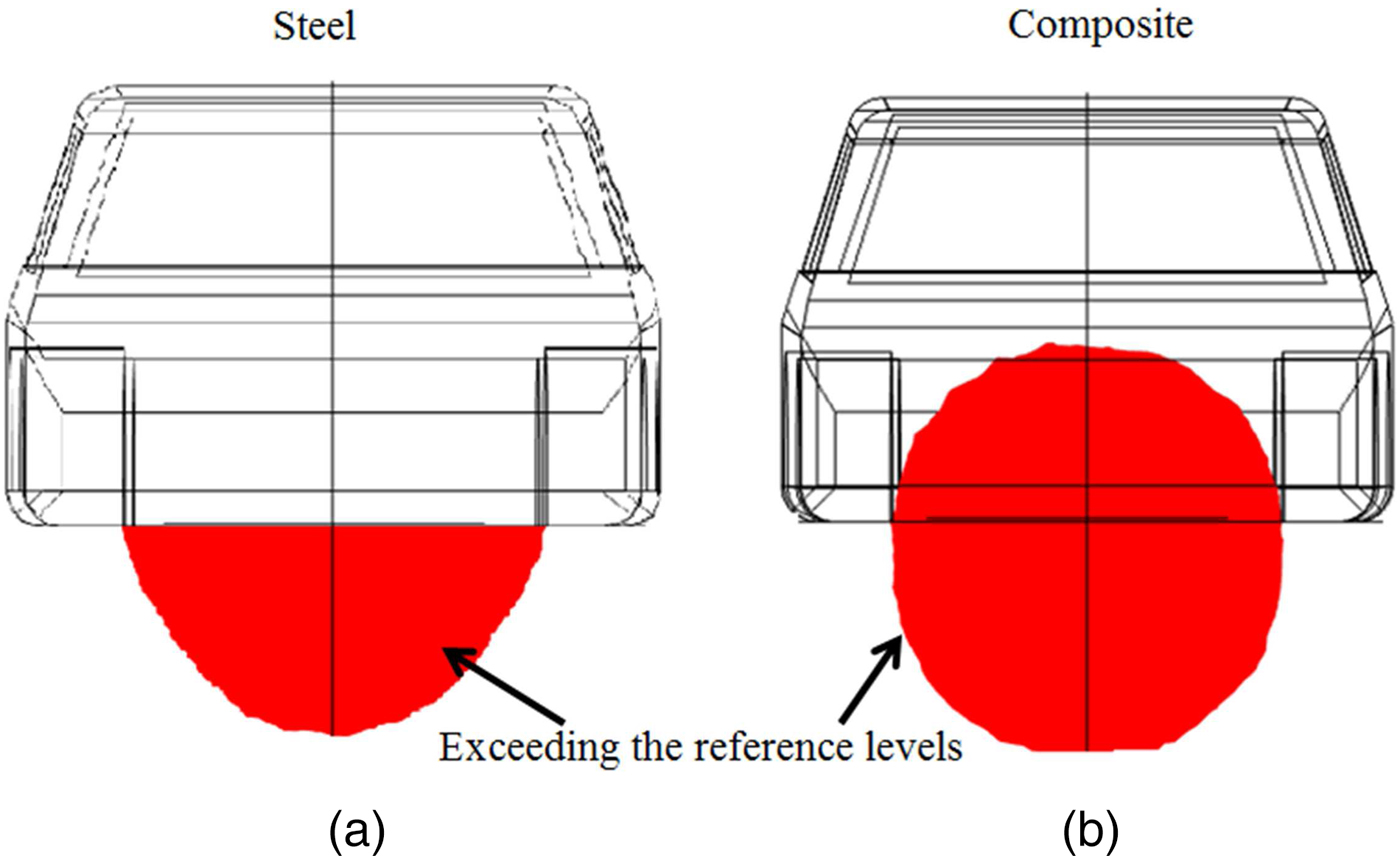
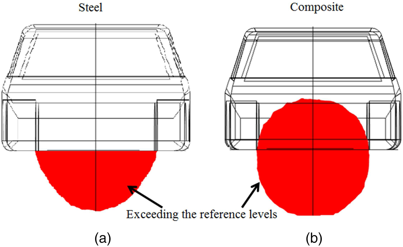
The magnetic field distribution inside the car is shown in Fig. 9 for different frequencies and conductive materials. The B-maps inside and outside the vehicle are reported in Fig. 10 for the three materials and the two frequencies, considering the WPT coil in position P 2. The cut plane is located at the center of the coils. The reference levels for both the considered frequencies is B RL = 27 µT (=28.63 dBµT) [5]. It is easy to note that for steel or aluminum chassis, the obtained values of magnetic field are far below the reference level. In particular for the aluminum frame, the maximum values are obtained near the apertures (car windows) rather than on the car floor. Much higher values are obtained for the composite structure, which is almost transparent for the magnetic field at the considered frequencies. In this case, the reference levels for both the considered frequencies are exceeded and a dosimetric analysis is needed to verify the compliance with the basic restrictions. The dosimetric analysis is not the focus of this work, and therefore it is not presented in this paper. It should be noted that in all cases, the field outside the car is lower than the reference levels with the exception of the zone under the car bottom. The zone where the reference levels is exceeded is shown as red areas in Fig. 11 for the most critical cases, in particular for composite and steel chassis at the frequency f = 85 kHz.
Magnetic flux density distribution in dBµT inside the EV.

Magnetic flux density distribution in dBµT inside and outside the EV.

Areas in which the magnetic field exceeds the reference level (B > 27 µT) at f = 85 kHz: steel frame (a) and composite frame (b).
IV. CONCLUSION
First, the TBC has been validated for its application in a numerical code to predict the magnetic field levels in an EV equipped with a 7.7 kW WPT system working at 85 and 150 kHz. A deep numerical investigation has demonstrated that the magnetic field levels are compliant with the EMF safety limits for an EV with metallic (iron or aluminum) chassis, at least for the considered configurations of WPT and car body. No any excess of the ICNIRP reference levels has been found inside the car, but only outside the cabin under the frame. On the contrary, the use of fiber composite for car body will produce the exceedance of the ICNIRP reference levels in the area where the legs of the passengers are located. Thus, a future investigation with dosimetric analysis will be necessary to evaluate the compliance, if any, with the ICNIRP basic restrictions.
 Tommaso Campi received the Laurea degree in telecommunication engineering from the University of L'Aquila, Italy, in 2014. He is currently working toward the Ph.D. degree in electrical engineering at the University of L'Aquila. His research interests include wireless power transfer and electromagnetic compatibility. He was the recipient of the Best Poster Presentation at the IEEE CEFC 2014, Annecy, France.
 Silvano Cruciani received the Laurea degree in information and automation engineering in 2010, and the Ph.D. degree in electrical engineering in 2015, both from the University of L'Aquila, L'Aquila, Italy. He is currently a post-doctoral researcher at the University of L'Aquila. His main research interests include numerical methods, electromagnetic wave propagation in complex media and wireless power transfer.
 Valerio De Santis received the Laurea degree (with honours) in telecommunication engineering and the Ph.D. degree in electrical and computer engineering, both from the University of L'Aquila, L'Aquila, Italy, in 2006 and 2010. He joined the Foundation for Research on Information Technologies in Society, IT’IS Foundation, Switzerland, from 2011 to 2013, holding the position of Project Leader and he was an Assistant Professor at the Nagoya Institute of Technology, Nagoya, Japan, from January to March 2015. He is currently a Fellow Researcher at the University of L'Aquila, L'Aquila, Italy. His current research interests include biological effects of electromagnetic fields, electromagnetic compatibility, and numerical methods and techniques. He is a senior member of IEEE and Secretary of IEEE-ICES-TC95-SC6 Commission. Dr. De Santis received the Second Best Student Paper Award at the Bioelectromagnetics Society (BEMS) Annual Meeting, Cancun, Mexico, 2006, the Best Student Paper Award at the IEEE International Symposium on EMC, Honolulu, HI, USA, in 2007, and the Leo L. Beranek Travel Grant at the IEEE International Symposium on EMC, Detroit, MI, USA, in 2008.
 Francesca Maradei received the Laurea degree in electrical engineering (cum laude) from Sapienza University of Rome in 1992, the Diplome d'Etudes Approfondies (DEA) in electrical engineering from the INPG, Laboratoire d'Electrotechnique de Grenoble, France, in 1993, and the Ph.D. degree in Electrical Engineering from the Sapienza University of Rome, Italy, in 1997. She joined the Department of Electrical Engineering at the Sapienza University in 1996 where she is currently professor. She has authored more than 150 technical papers in the field of computational electromagnetics and EMC. She received the 2015 Laurence Cumming Award for outstanding service to the IEEE EMC society over the last ten years including a term as President, two terms as a member of the Board of Directors, service as chapter coordinator, and contributing to the global outreach and overall success of the EMC Society. She received also the James Melcher Price Paper Award with the paper “Analysis of upset and failures due to ESD by the FDTD-INBCs method”, IEEE Trans. Industry Applications, vol. 38, no. 4, Jul./Aug. 2002, pp. 1009–1017; the Oral Presentation Best Paper Award at the International Symposium on Electromagnetic Compatibility - EMC ROMA 1994, Rome, Italy, and the Poster Presentation Best Paper Award at the EMC EUROPE 2000, Bruges, Belgium. Prof. Maradei was President (2010–11) of the IEEE Electromagnetic Compatibility Society. She was an Associate Editor of the IEEE Transactions on Electromagnetic Compatibility from 1999 to 2000. She is a member of the EMC Europe International Steering Committee, and since 1998 she is a member of the Editorial Board of IEEE Conference on Electromagnetic Field Computation (CEFC) and of COMPUMAG Conference.
 Mauro Feliziani received the degree in electrical engineering from the University of Rome La Sapienza, Rome, Italy, in 1983. From 1987 to 1994 he was with the University of Rome “La Sapienza” as a Researcher (1987–1990), Assistant Professor (1990–1992) and Associate Professor (1992–1994). In 1994 he joined the Unversity of L'Aquila, Italy, as Full Professor of Electrical Engineering. He is the author or coauthor of more than 150 papers published in the fields of electromagnetic compatibility (EMC) and in electromagnetic field numerical computation. His current research interests include RFID, ultra-wideband, wireless power transfer, wireless communications and bioelectromagnetics. Prof. Feliziani was the recipient of the Best Paper Award of the IEEE Transactions on Industry Applications in 1995, the Electrostatics Process Committee and the EMC Europe Symposium, in 2000. He was also co-author of: Best Student Paper at the IEEE International Symposium on EMC, Honolulu, USA, 2007; Second Best Student Paper at the BEMS Annual Meeting, Cancun, Mexico, 2006; Best Poster Presentation at the IEEE CEFC 2014, Annecy, France. From 1995 to 2000, he was an Associate Editor of the IEEE Transactions on Electromagnetic Compatibility. In March 2003, he was the Guest Editor of a special issue of the IEEE Transactions on Magnetics. In 2008, he was the Guest Editor of a Special Section of COMPEL. In 1994 he was co-founder of EMC Europe Symposium. He was the General Chairman of the EMC Europe Symposium, Sorrento, Italy, in 2002, and of the EMC Europe Workshop, Rome, in 2005. He was the Technical Program Committee Chair of EMC Europe 2012, Rome, Italy. He was the Chair of the International Steering Committee of the EMC Europe Symposium 2012–2015.