

Abnormalities of the mitral valve constitute a rarely seen group of congenital abnormalities. In his study, Banerjee noted that the incidence of mitral anomalies accounted for 0.36% of the cases referred for echocardiography in a paediatric cardiology practice, although the survey did not include abnormalities such as mitral valvar prolapse and straddling mitral valves.Reference Banerjee, Kohl and Silverman1 In this manuscript, and based on my own experience with these lesions, I will show the echocardiographic features of congenital mitral stenosis, supravalvar mitral rings, clefts in the mitral valve, double orifice, and accessory mitral valve, and their relationship with pathological specimens, including the lesions of mitral valve prolapse and straddling mitral valves. In the paediatric age range, these lesions are found rarely, their surgical treatment remains difficult, and they have high associated morbidity and mortality. The presentation of these lesions varies widely, presenting either with obstruction to left-sided flow, regurgitation, or both.
Excellent reviews dealing with normal and abnormal valves and the techniques to investigate them have already been published.Reference Banerjee, Kohl and Silverman1–Reference Biaggi, Greutmann and Crean9 Detailed descriptions of the techniques and methods to evaluate both the normal and abnormal mitral valves are beyond the scope of this manuscript. The purpose of this presentation is to demonstrate the major echocardiographic features of these lesions and to correlate them with other morphological techniques such as pathological specimens and intra-operative images to better understand the echocardiograms.
Echocardiographic methods
In this study, a full complement of echocardiographic modalities was used, the predominant tools being two-dimensional echocardiography complemented by both pulsed-wave and continuous-wave Doppler interrogation and Doppler colour-flow techniques. All aspects of imaging valve morphology, from the supravalvar to the valvar components, to the support structure and papillary muscles that support the valve, were evaluated. Now that the value of three-dimensional echocardiography is more widely accepted, the standard approach is to use this technique wherever possible. The various two- and three-dimensional approaches require a full complement of views, even extending to the use of trans-oesophageal echocardiography as part of monitoring surgical repair. For three-dimensional echocardiography, a full complement of techniques is used, including live three-dimensional and full-volume acquisition as well as three-dimensional zoom modes to render the best image in the shortest amount of time. These techniques have been complemented by the modalities of pulse-wave and continuous-wave Doppler ultrasound to assess transmittal flow signals and peak velocities of flow. The addition of Doppler colour flow techniques has proved invaluable for differentiating the complex multi-level sites of obstruction that may occur with the various lesions, and this technique may also define the site of origin and aetiology of mitral regurgitation.
Patient demography
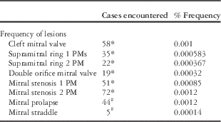
Over a 14-year period, spanning my work at the University of California, San Francisco, and Stanford University, 36,600 individual patients were evaluated. I added the original data from Banerjee’s study for the lesions surveyed in that study.Reference Banerjee, Kohl and Silverman1 The population base for that study was 13,400, of whom 24 patients had mitral stenosis with one papillary muscle, 24 patients had mitral stenosis with two papillary muscles, 10 patients had isolated clefts in the mitral valve, and seven patients had double orifice mitral valve. The total number of new admissions and the period in which they were studied were added to the 36,600 new patients from our database. The total number of patients for those lesions is based on 60,000 new admissions to the echocardiographic laboratory over 21 years, and includes frequency calculations for supravalvar rings, double orifice, cleft mitral valves, and mitral stenosis. As the patients with mitral prolapse and straddling valves were not included in this study, their frequency was computed from our 14-year database of 36,600 new admissions. The frequency of each of these disorders is given in Table 1.
The table shows the frequency of the congenital lesions of the mitral valve encountered in this series of patients.
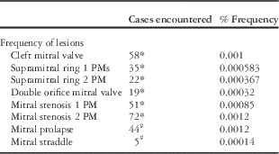
PM=papillary muscle
*Estimated frequency from 60,000 patients
#Estimated frequency of 36,600 patients
The first group (as indicated by the asterisk) is from the current series, also incorporates the population from Banerjee,Reference Banerjee, Kohl and Silverman1 and includes 60,000 patients over 21 years.Reference Séguéla, Houyel and Acar5 The last two conditions were only from my current database of 36,600 patients over 14 years
Lesions
When reviewing mitral valvar anomalies, it is not surprising to find that the components of valve pathology vary widely. For example, predominantly stenotic valves may have a cleft and a supravalvar ring, whereas double orifice valves may have only one valve with a cleft. Defining all of the various components by echocardiography remains a challenge, and thus for the purposes of presentation each will be discussed separately.
Supravalvar mitral ring
We studied 67 patients in this series, including the 10 patients reported in the Banerjee series.Reference Banerjee, Kohl and Silverman1 Supravalvar mitral ring rarely occurs as an isolated lesion, being more frequently associated with mitral stenosis or with other forms of heart disease. Banerjee’s original series presented 21 cases, of which 17 (81%) were associated with mitral stenosis with one papillary muscle, the so-called Shone syndrome, whereas four (19%) were found to have mitral stenosis with two papillary muscles. In the combined series that we subsequently studied, we found 35 cases associated with mitral stenosis and one papillary muscle and 22 with two papillary muscles (Table 1). There were no patients with a supravalvar ring without other associated lesions.
Pathologically, the ring can be identified above the plane of the valve or on the atrial surface of the valve itself (Fig 1). A full complement of two-dimensional views was required to assess the valve, including views that provide an en-face view, such as the parasternal short-axis or subcostal short-axis view, as well as views that provide a cross-section of the lower surface of the left atrium and the valve funnel, such as the apical and four-chamber view, the subcostal four-chamber view, and the parasternal long-axis views (Fig 2).
Top: this pathology specimen is cut in conventional manner and viewed from the posterior aspect, and shows a supravalvar mitral ring (black arrows). The rim can be seen in the left atrial surface (LA) above the mitral valve (MV) and left ventricle (LV). Bottom: this is an intra-operative example of a supravalvar mitral ring (arrows) from the left atrial (LA) aspect. The anterior (AML) and posterior (PML) leaflets can be seen through the ring.

These are consecutive beats taken from a trans-oesophageal echocardiogram in long-axis orientation. The supravalvar ring (arrows) can be seen in the funnel of the mitral valve. The bottom frame shows well-marked proximal isovelocity surface area acceleration at the site of the ring. The signal is aliased at the point where it turns from turquoise to yellow. A=anterior; AO=aorta; I=inferior; LA=left atrium; LV=left ventricle; P=posterior; S=superior.
In our earlier series, we found that this ring occurred in both types of mitral stenosis, but more frequently in patients with mitral stenosis with one papillary muscle. We found that supravalvar mitral ring occurs more commonly in mitral stenosis with one papillary muscle than two papillary muscles (81% versus 19%; Table 1).
The presence of a supravalvar ring should be suspected in any lesion associated with congenital mitral stenosis. The ring is often present in the funnel of the valve on its atrial surface, rather than being supravalvar in nature. In some instances, the ring may be subtle and seen only as a small ridge on the inlet of the mitral valve, whereas in others it is much more prominent. The use of three-dimensional techniques provides a greater insight into the extent and position of the ring and its relation to the valve (Fig 3). Although Doppler ultrasound can predict a pressure drop across a valve, it is often difficult to define which component of the lesion is causing more significant obstruction. The use of Doppler colour flow imaging is valuable because it can define the proximal isovelocity surface area at the point where the ring becomes obstructive (Fig 2).
This figure represents a three-dimensional live trans-oesophageal echocardiogram from a patient with a supravalvar mitral ring (arrows). The funnel of the MV is seen. LV=left ventricle; MV=mitral valve; RV=right ventricle. This frame is published with permission from Dr Pei-Ni Jone and Dr Adel Younoszai from the University of Colorado.
Mitral valve clefts
Clefts in the mitral valve not associated with atrioventricular septal defects are now more commonly found than they were before the echocardiographic era, because, in the past, mitral clefts were only recognised if there was mitral regurgitation, or if the patients with these clefts were referred for surgery, or when this lesion was part of an associated cardiac disorder. We have had experience with a variety of these lesions.Reference Banerjee, Kohl and Silverman1, Reference Kohl and Silverman6–Reference Punn and Silverman8 Clefts may be defined by two- and three-dimensional echocardiography. The cleft in the mitral valve is associated with several forms of heart diseases, including ventricular septal defects, double-outlet right ventricle, transposition of the great arteries, tricuspid atresia, and double-chambered right ventricle.Reference Banerjee, Kohl and Silverman1, Reference Kohl and Silverman6–Reference Punn and Silverman8 Although clefts occur predominantly on the anterior leaflet, there are reports of clefts occurring on the posterior leaflet as well.Reference Biaggi, Greutmann and Crean9, Reference Seguela, Brosset and Acar10
Our current series consists of 58 cases of cleft mitral valve, including the 10 patients we reported previously (Table 1).Reference Banerjee, Kohl and Silverman1 The normal anterior mitral valve leaflet occupies one-third of the circumference of the mitral annulus, and the posterior leaflet occupies two-thirds of the circumference. The same relationship occurs with an isolated cleft in the mitral valve, but it is different from the atrioventricular septal defect where the mural leaflet of the valve is substantially smaller. Kohl and SilvermanReference Kohl and Silverman6 investigated both the position of the cleft and that of the papillary muscles in the left ventricle (Fig 4). The position of the cleft, as opposed to its usual position in atrioventricular septal defects, was found to vary greatly.Reference Kohl and Silverman6 It is accepted that the papillary muscles are situated in such a way that they support the valvar commissures of the mitral valve, and therefore their position subtends the arch of both leaflets. We found that, in the atrioventricular valve with a commissure or cleft – as it is more regularly called – the papillary muscle rotation changes the position of both papillary muscles in a counter-clockwise direction, whereas the papillary muscle position is more conventional in isolated mitral clefts. The mural leaflet of the mitral valve is much larger than the mural leaflet of the valve in atrioventricular septal defects (Fig 4).
Top frame: This frame shows a diagrammatic representation of the position of the anterolateral and posteromedial papillary muscles in the normal mitral valve and the arc between them. The junction of the posterior right and left ventricle is marked at 0°. The position of the papillary muscles was recorded from the bases of the papillary muscles as degrees of clockwise rotation from this origin. Middle frame: This frame shows the position of the papillary muscle in the situation of cleft mitral valve and also where it would be in atrioventricular septal defect. The medial papillary muscle is shown in black and the lateral leaflet in grey.Bottom frame: This frame shows the position of the mitral cleft in 10 children with isolated cleft mitral valves (Dark lines). The long bold line indicates the mean axis of 51 degrees. The short dotted lines indicate the cleft in nine children with atrioventricular septal defects. The mean axis in these nine patients was 36 degrees, indicated by a short bold line (Abbreviations remain the same) Abbreviations: AVSD=atrioventricular septal defect; CL-MV=cleft mitral valve; RV=right ventricle; LV=left ventricle. Published with permission from the American Journal of Cardiology from reference.Reference Kohl and Silverman6
With a ventricular septal defect, the cord attaches to the crest of the septum or may be traced to a papillary muscle or anchor within the right ventricle (Fig 5). Although very occasionally clefts are not attached to the ventricular septum by chordae tendiniae, there is almost always an attachment, seen in both long-axis and short-axis views. Although not well seen from the atrial surface of the valve, the attachment is much better defined from the ventricular view seen by two- or three-dimensional echocardiography (Fig 5).
The two frames are from a specimen with tricuspid atresia and a cleft on the anterior leaflet of the MV. The top frame shows a cleft mitral valve from the upper surface of the MV. The cleft and the cordal attachment of the valve extend to the margin of the VSD. This frame is reproduced courtesy of Profesor Robert Anderson. The bottom frame shows the left ventricle opened in clamshell fashion and demonstrates the tricuspid nature of the valve. The A leaflet is cleft and the chordae extend to the crest of the ventricular septal defect. The ML is large and in normal position. A=anterior; AO=aorta; MV=mitral valve; ML=mural leaflet; VS=ventricular septum; VSD=ventricular septal defect; S=septum.
In addition to the cleft, the cordal attachment to the crest of the septum is clearly seen by both two-dimensional and three-dimensional echocardiography in the parasternal short-axis or other en-face views. The Doppler colour flow signal usually originates at the site of the cleft in the valve (Figs 6 and 7).
A two-dimensional P SAX view (top) and a corresponding three-dimensional echocardiographic view (bottom) in the same patient are shown. This patient had an isolated cleft in the mitral valve. The top frame shows the two components of the cleft in the anterior leaflet of the mitral valve (arrows). The CT are attached to the crest of the septum as shown in Figure 4 (bottom). The PML occupies its normal position. The bottom frame is a live three-dimensional view showing the anterior leaflet with a cleft and attachment of the tendinous cords to the underlying left ventricular septal surface. CT=chordae tendiniae; PML=posterior mitral valve leaflet; P SAX=parasternal short axis; RV=right ventricle.
These P SAX views are from consecutive views of the mitral valve in a patient showing a cleft mitral valve (top). Mitral regurgitation is demonstrated by Doppler colour flow mapping (bottom). The cleft (CL) in the valve is shown in the top frame with attachment of the chordae tendiniae to the left ventricular surface of the septum (arrow). The Doppler colour frame is taken in late systole, as can be seen on electrocardiogram, and demonstrates the jet passing through the region where the cleft is opposing the posterior mitral leaflet. CL=cleft; P SAX=parasternal short-axis; RV=right ventricle.
Cordal attachments can also be recognised from the apical views, from the cardiac apical location and from the parasternal long-axis views (Figs 5 and 8). When there is a ventricular septal defect, the cord attaches to the crest of the septum, or may be traced to or through the ventricular septal defect to a papillary muscle or anchor within the right ventricle.
This P LAX demonstrates the chordal attachment of the cleft anterior mitral leaflet to the ventricular septum (arrow). AO=aorta; CL=cleft; LA=left atrium; LV=left ventricle; P LAX=parasternal long-axis view; RV=right ventricle.
Clefts with mild degrees or no mitral regurgitation occur more commonly but present clinically only when mitral regurgitation is present or when associated with other mitral valvar pathology or other structural congenital heart disease. Mitral regurgitation from the cleft varied from none to mild to severe.
Double orifice mitral valve
In his series of congenital anomalies of the mitral valve, Banerjee found a double-orifice mitral valve, which was detected only in seven of 65 patients (11%).Reference Banerjee, Kohl and Silverman1 When added to our more recent experience, the total number of patients with this condition was 19 (Table 1). Of the additional 12 patients, two had associated clefts with cordal attachment to the clefts of the septum from one or other orifice, and two were caused by obstruction of the left ventricular outflow by the medial orifice.
Double orifice may be divided pathologically into double orifice with reduplication of the valve annulus, double orifice with an annular origin of a mitral orifice, or membranous fusion of the valve by a connecting tongue (Fig 9). The lesion may be isolated, but it was often found with associated defects, varying from something as simple as a ventricular septal defect to as complex as an association with common arterial trunk, or with univentricular atrioventricular connection, and may be of varying presentation.Reference Bano-Rodrigo, Van Praagh and Trowitzsch11–Reference Bano-Rodrigo, Van Praagh, Trowitzsch and Van Praagh16 The echocardiographic approach to these lesions is to define the valve in cross-sectional and longitudinal views by cross-sectional echo and to provide an en-face view of the valve by three-dimensional echocardiography (Figs 10–13). The valvar orifices were of equal size, but more commonly the orifices vary, with one valve being larger, termed the dominant orifice, and the other being smaller, termed the secondary orifice (Fig 13). Some accessory orifices were sometimes difficult to define echocardiographically because the examiner observed the lesion towards the position of the free edge of the main leaflet, whereas the lesion actually lay near the annulus of the valve (Fig 9, middle frame).
This figure demonstrates the various types of pathological variation in double orifice MV pathology. The top frame shows a double orifice with reduplication of the annuli of the valve, which are labelled MV1 and MV2. The LAA and TV are labelled for orientation. This figure is courtesy of Professor Robert Anderson. In the middle panel is the type of double orifice with one mitral orifice (MV2) at the annulus of the valve adjacent to the LA. A tendinous cord from this attachment can be seen adjacent to the label. The main orifice of the valve is evident on the ventricular aspect (MV1) of the left ventricle. The bottom frame shows a double orifice MV with only a membranous connection dividing the orifice. This specimen is also viewed from the posterior aspect. The LA is seen above the valve. This figure is courtesy of Professor Robert Anderson. MV=mitral valve; LAA=left atrial appendage; TV=tricuspid valve; LA=left atrium; LV=left ventricle.
This figure was taken from the parasternal short-axis view (P SAX) in a patient with a double orifice mitral valve providing an en face view of the valvar orifices of the mitral valve. The median mitral orifice (MV1) is slightly larger than the lateral orifice (MV2), which is also cleft (CL). The right ventricle (RV) is seen anteriorly.
The top frame was taken from the subcostal sagittal view in diastole and shows near equal size of the two mitral orifices (MVO 1 and MVO 2). The right ventricle (RV) is seen anteriorly. The bottom frame was taken at the same point in the cardiac cycle and shows the low velocity Doppler colour flow signals though both orifices.
This apical four-chamber view was taken from a patient with an atrial septal defect. The left frame demonstrates the valve in the black and white image and shows two orifices of equal size – MV1 medially and MV2 laterally. The area between the valves has a low signal, an indication of the membranous nature of this type of morphology (compare with Figure 9 bottom). The right frame shows the corresponding Doppler colour flow signal with the flow in diastole being directed through the two orifices. The medial orifice has a slightly higher velocity signal. DAO=descending aorta; LA=left atrium; LV=left ventricle; MV=mitral valve; RA=right atrium.
This en face view of the mitral orifices demonstrates a comparison between the techniques of two-dimensional echocardiography (top) and three-dimensional echocardiography (bottom). Both two orifices are imaged, demonstrating the relative sizes of both orifices. MV1 (medially) is large and MV2 (laterally) is small. It appears that the two techniques display the pathology equivalently. LV=left ventricle; MV=mitral valve; P SAX=parasternal short-axis view; RV=right ventricle.
In some of our patients, in addition to stenosis of one of the orifices there was an additional cleft in the valve, which arose either laterally or medially to the orifice. The normal mitral valve has no septal attachment but the accessory valve most frequently has this cordal attachment to the medial or lateral orifices (Fig 10).
Viewing the valve from long-axis views allowed for a different perspective, providing the opportunity to assess the nature of the medial orifice’s attachment to the ventricular septum and to assess the magnitude of flow through the valve. Apical and parasternal long-axis views, therefore, were useful for assessing the degree of mitral obstruction to left ventricular outflow from Doppler colour flow images (Fig 12).
In some pathological specimens, the medial orifice of the valve may be small and may seem to obstruct the outlet of the ventricle (Fig 14). The lesion may have mild obstructive features or may cause significant obstruction. Surgical removal was accomplished by removing this obstruction through the aortic valve (Fig 15). The echocardiographic display of the accessory orifice, whether or not it caused an obstruction, was observed from a variety of views and correlated well with the pathological findings. Display of this lesion was best defined by views of the left ventricular outflow tract – namely, the parasternal and apical long-axis views (Figs 16 and 17). The apical view also provided the best alignment for Doppler ultrasound to define the severity of the obstruction. The accessory valve was seen not only from subcostal views of the left ventricular outflow tract but also from the parasternal short-axis views, where the lesion was sometimes seen entering the funnel of the opened aortic valve.
This specimen shows an ACC MV orifice as part of a double orifice mitral valve obstructing the left ventricular outflow tract. The obstructive orifice sits in the left ventricular outflow tract proximal to the AO and aortic valve. The other part of the mitral valve orifices lies on the distal portion of the valve. Note also that, in this specimen, there is a cleft in the mitral valve with cordal attachment (arrows) to the crest of the VSD. ACC MV=accessory mitral valve; AO=aorta; PM=papillary muscle; VSD=ventricular septal defect.
This image is from a surgical procedure taken from a patient with a double orifice mitral valve with obstruction of the left ventricular outflow tract. The patient is on bypass and the cranial aspect is at the top of the image. The aorta has been opened and transected. The ascending aorta (AO) is held with forceps and the accessory tissue (ACC MV) has been pulled through the aortic valve with a suture before its excision.
This is an apical five-chamber view (top frame) taken just after aortic valve closure. The accessory MV orifice is seen as a small circle (arrow) within the left ventricular outflow tract. The bottom frame is taken in the P LAX in systole. The aortic valve leaflets (small arrows) are in the open position. The ballooning ACC MV orifice is attached to the larger MV and the ventricular septum across theLVO tract. AO=aorta; A AO=ascending aorta; LA=left atrium; LV=left ventricle; LVO=left ventricular outflow; MV=mitral valve; P LAX=parasternal long-axis view; RA=right atrium; RV=right ventricle; RVO=right ventricular outflow.
This apical five-chamber view shows a black and white image in the top panel and the corresponding Doppler colour flow image in the bottom panel taken in systole. In the top panel, the accessory mitral orifice (access MV) is tethered to the ventricular septum by tendinous cords. The orifice obstructs flow with a well-marked aliasing of the colour signal observed in the bottom frame at the site of the obstructing accessory valve tissue. AO V=aortic valve; LA=left atrium; LV=left ventricle; MV=mitral valve; RV=right ventricle.
Mitral valvar stenosis
Many ultrasound diagnostic refinements have been made since the early studies of Collins-Nakai et al, Ruckman et al, and Moore et al for the assessment of mitral stenosis.Reference Collins-Nakai, Rosenthal and Castaneda17–Reference Moore, Adatia and Spevak19 The prognosis for these patients remains guarded. If the left ventricle is very small, it may not practically be considered mitral stenosis but rather a part of hypoplastic left heart syndrome. Patients with this lesion who undergo surgery have substantial morbidity and mortality. Using the data from the Banerjee studyReference Banerjee, Kohl and Silverman1 with the series from my current database, there were a total of 123 patients with mitral stenosis. A total of 51 patients had mitral stenosis with one papillary muscle, a frequency of 0.00085%, and 72 patients had mitral stenosis and two papillary muscles, including the patients from the study by Banerjee, a frequency of 0.0012% (Table 1).
Congenital mitral stenosis, with two papillary muscles
Echocardiography of the mitral valve showed a limited opening of the valve leaflets in the long axis and thickened valve leaflets with restrictive excursion (Fig 18). The leaflets were found to be dysplastic in 58% of patients. Images were obtained from many different planes and displayed with varying success, and hence a multi-modal approach including two-dimensional and three-dimensional echocardiography was necessary to define the best view from which to display the leaflets (Figs 19 and 20). It is important to define the papillary muscles in the short-axis or subcostal sagittal views in order to define whether there are two papillary muscles and whether the leaflets are attached to both. The papillary muscle connection was obtained with sweeps by two-dimensional or three-dimensional echocardiography (Fig 19, bottom). The apical or subcostal views can also display the distorted excursion of the valve in real time, the decrease in the mitral orifice, and the size of the jet and proximal flow acceleration with colour flow (Figs 18 and 20). A supravalvar mitral ring was less frequently encountered than in the single papillary muscle situation seen in Shone’s complex (Fig 21; Table 1).
This figure is a composite of the black and white image (top) and the Doppler colour flow image (bottom) in the P LAX view showing the thickened edges of the stenotic mitral valve (arrows) lying between the LA and LV. In the top frame, the mitral leaflets were frozen at their peak of opening and show restricted opening and thickening of the edges of the valvar leaflets. The tendinous cords of the leaflet are also thickened and the anterior leaflet cord is evident. The LA is markedly enlarged. In the bottom frame, taken at the same time in the cardiac cycle, the consequence of mitral stenosis is evident with a well-marked proximal isovelocity area in yellow, just proximal to the red flow signal, as a consequence of the stenosis. There is also a narrow jet of blood passing through the mitral valve into the left ventricle. AO=aorta; LA=left atrium; LV=left ventricle; P LAX=parasternal long axis; RV=right ventricle.
This figure shows short axis “en face” views of the mitral valve in the same patient with mitral stenosis associated with two papillary muscles. The top frame shows the two-dimensional view and the bottom frame the three-dimensional view. In the top frame, the MV is thickened and indicated by arrows. The shape of the valve suggests the presence of the papillary muscle at the junction of the two leaflets. The bottom three-dimensional view shows the thickened mitral leaflets and the origin of the papillary muscle (arrows). MV=mitral valve; P SAX=parasternal short axis; RV=right ventricle.
This apical four-chamber view is of the same patient shown in Figure 18. The top frame, taken at peak opening, shows the thickened leaflet tips with poor excursion and a stenotic orifice. The LA is markedly enlarged. The bottom frame, taken at the same point in the cardiac cycle as the top frame, shows the narrow stenotic jet passing through the valve and the aliased proximal acceleration in yellow in the LA as the blood accelerates towards the orifice. LA=left atrium; LV=left ventricle; RA=right atrium; RV=right ventricle.
This example of mitral stenosis with two papillary muscles (arrows) and a supravalvar mitral ring (ring) was obtained from the subcostal four-chamber view. The ring lies within the atrial funnel of the stenotic mitral valve. LA=left atrium; LV=left ventricle; RA=right atrium; RV=right ventricle.
As opposed to the situation in adults where the diastolic period is relatively longer, the classical features of mitral stenosis are not reproduced in children (Fig 22). Peak “e” wave and pressure half-times and estimated mitral valvar areas were poorly defined by Doppler ultrasound.Reference Banerjee, Kohl and Silverman1 There are several reasons for the disparity. Frequently, an associated atrial communication exists because the lesion, when discovered at birth, has been developing during most of the pregnancy and the foramen is frequently incompetent with this pathology. In addition, the diastolic period of mitral filling is substantially shorter in these infants because of faster foetal heart rates, and the pressure decay is too short for pressure half-time decay to be appreciated. The “e” and “a” periods are often fused and, as the atrial contraction is more important in the young patient, the most frequently observed signal is an elevated “a” wave peak on the Doppler tracing. Lastly, the immature myocardium is less compliant than it is in adults. As the stress of this lesion has been present throughout foetal life, the ventricle is less compliant than it is in older patients and the pattern of mitral stenosis in children is different. With associated distal left ventricular outflow tract pathology, the left ventricle may be thickened, as is often the case, and the hypertrophy and endocardial thickening produces diastolic dysfunction of the ventricle that further complicates the character of the trans-mitral flow signals. The peak velocities were increased and, because of the importance of the atrial contraction in ventricular filling in small children, the peak “a” waves were often higher than the “e” waves (Fig 22). Doppler colour flow provided valuable information about jet direction and velocity, as well as the presence of mitral regurgitation. The vena contracta provided another estimate of the degree of the mitral valve area (Figs 18 and 20).
This pulsed Doppler colour flow signal was obtained from a child with mitral stenosis and shows the characteristic features of the pulsed Doppler signal across the mitral valve. The heart rate in this child is 115 beats/minute. The “e” and “a” waves representing early diastolic filling and atrial contraction, respectively, are fused so that there is no period for the e wave to decline before the a wave because of the faster heart rate. The ‘a’ wave has a velocity of 2.2 m/s >16 mmHg pressure drop.
A rare anomaly in mitral stenosis is the so-called mitral hammocking or arcade.Reference Collins-Nakai, Rosenthal and Castaneda17–Reference Edwards and Layman20 We encountered only three cases in which we could define this lesion by echocardiography. Pathologically, this form of mitral stenosis involves an obliteration of the tensor apparatus of the mitral valve. The intercordal spaces are absent, with continuity between the papillary muscle and the free edges of the leaflets (Fig 23). Focal endocardial thickening is considered to be part of this lesion; however, some purist pathologists exclude an arcade in the presence of severe diffuse endocardial fibroelastosis, as found in diminutive left ventricles that might be considered part of the spectrum of hypoplastic left-heart syndrome. This lesion leads not only to poor mobility of the leaflets but, as is the case with most forms of mitral stenosis with two papillary muscles, also to poor leaflet coaptation, and also shows echocardiographic evidence of mitral regurgitation. Although the pathology is clear, it has been difficult to define the absence of clear tendinous cords prospectively through echocardiography, especially in the presence of a thickened mitral valve. Characteristically, a continuum from valvar tissue to papillary muscles was seen by using a combination of views by which papillary muscles and mitral valvar tissue could best be defined, from the parasternal long-axis and apical views (Fig 24).
This pathologic specimen was opened from the posterior aspect of the LV and displays the AML valve. The leaflet is connected to the PM in the LV and there are no tendinous cords evident as the valve is attached directly to the PM. AML=anterior mitral leaflet; LA=left atrium; LV=left ventricle; PM=papillary muscles.
These two frames are from a patient with a mitral arcade. The top frame is taken from the apical four-chamber view. The thickened stenotic MV merges directly with the PM. The bottom frame shows the same patient from a parasternal long-axis view, again showing the merging of the MV leaflet directly to the PM. LA=left atrium; LV=left ventricle; MV=mitral valve; P LAX=parasternal long axis; PM=papillary muscle; RV=right ventricle.
Congenital mitral stenosis, with one papillary muscle, Shone’s complex
The paper written by Shone, of which Dr Jesse Edwards was first author, brought attention to the complex of a mitral valve with a single papillary muscle – the so-called Shone’s complex.Reference Shone, Sellers, Anderson, Adams, Lillehei and Edwards21 In this condition, the authors noted the following features.A parachute mitral valve, supravalvar mitral ring, subaortic stenosis, and coarctation of the aorta. These lesions remain rare in pathology collections (Fig 25). In only two of the original cases of Shone et al were all four conditions present; the other six had at least two of these features. In some of the cases, the entities, although present, seemed not to have been responsible for producing significant haemodynamic effects. As the scope of this section is to discuss the mitral valve, I will confine my comments to the mitral valve, papillary muscle, and supravalvar association. In Banerjee’s study, the number of patients with single papillary muscle mitral stenosis was the same as those with mitral stenosis with two papillary muscles – that is, 37% of the original case cohort.Reference Banerjee, Kohl and Silverman1 Among them, 10 were complete Shone’s complexes and 24 were incomplete, having a single papillary muscle and parachute mitral valve; however, in my current series, there were fewer cases of mitral stenosis with one papillary muscle (51 cases) than of mitral stenosis with two papillary muscles (72 cases) (Table 1). Echocardiographic cross-sectional views across the plane of the valve from the annulus defined the position of the valvar pathology and the position of the papillary muscle. These were either short-axis parasternal views or corresponding views from the subcostal sagittal plane (Figs 26 and 27). The apical views were also helpful for noting the papillary muscle attachment, the supravalvar mitral ring, and the papillary muscle attachment (Fig 28). Slight anterior angulation into the subaortic area enabled identification of the subaortic membrane frequently found in this syndrome.
This pathological specimen, opened in clamshell manner, shows a patient with Shone’s complex and a parachute mitral valve, previously diagnosed by echocardiography. The patient has a StJude® prosthetic valve in the aortic position (AO V) with substantial fibrous callus accumulated under the prosthetic valve. The parachute mitral valve (PMV) is seen to attach to a single papillary muscle (SPM). There are numerous false tendons (FT), which had to be cut in order to display the valve. The left ventricular wall (LVW) is labelled and is hypertrophic.
This PSAX taken in one cardiac cycle shows the solitary single medial papillary muscle (top frame) and the parachute small MVO in the bottom frame as the heart twists and contracts during the cardiac cycle. LV=left ventricle; MVO=mitral valve orifice; MPM=medial papillary muscle; P SAX=parasternal short-axis view; RV=right ventricle.
This subcostal sagittal view taken in one cardiac cycle shows the solitary single medial papillary muscle in the top frame and, as the heart twists and contracts, the parachute small MV in the bottom frame. LV=left ventricle; MV=mitral valve; RV=right ventricle; SPM=single papillary muscle.
In this apical four-chamber view in a patient with Shone’s complex, the mitral valve chordae tendiniae are seen to connect to the solitary left ventricular PM. A supravalvar mitral ring (ring) is noted in the mitral funnel. LA=left atrium; LV=left ventricle; PM=papillary muscle; RA=right atrium; RV=right ventricle.
The issue of the supravalvar ring might incline one to believe that mitral stenosis is more likely to be associated with the lesion described by Shone. In our current database of 57 patients, a supravalvar ring was associated with a single papillary muscle in 62% and with two papillary muscles in 38% of our patients. This frequency does not permit one to assume the papillary muscle status based only on the presence of a supravalvar ring.
Mitral prolapse
This lesion is not encountered as frequently in younger children, unless associated with syndromes such as Marfan’s syndrome or other connective tissue disorders such as mucopolysaccharidosis. In our database, 44 patients had mitral prolapse, including patients with Marfan’s syndrome, cleft mitral valves, atrial septal defects, and Hurler’s syndrome. Pathologically, leaflet billowing of one or more commissural scallops of either valve leaflet or redundancy of the leaflets was observed, and associated cordal rupture was noted (Fig 29). Infective endocarditis, which is a complication of this condition, was also identified echocardiographically or pathologically.
This is a pathological example of mitral valve prolapse involving the PML of the valve. There is no prolapse of the AML valve. The prolapse, in this instance, involves a medial commissural scallop of the posterior (or mural) leaflet of the mitral valve. The chordae tendiniae supporting this leaflet of the valve are elongated, participating in the prolapse of the valve. AML=anterior mitral leaflet; LA=left atrium; PM=papillary muscle; PML=posterior mitral leaflet. This figure is provided courtesy of Professor Robert Anderson.
As seen with echocardiography, mitral leaflets were often thickened and rolled, and the tendinous cords were more prominent. The echocardiographic view that best displayed the mitral prolapse was the long-axis or four-chamber view, from which the mitral valve and its annular attachments were observed (Figs 30 and 31). Various parts of the leaflet may exhibit prolapse at different times during systole; therefore, the entire cardiac cycle needs to be assessed for timing, which is frequently late but may be holosystolic in nature. Although billowing of one or more parts of the valve can be identified in different ways, it was only with real-time echocardiography such as two- or three-dimensional echocardiography that the functional nature of valvar prolapse could be evaluated. Following diminution of ductal or ventricular septal defect shunting, either surgically or as part of the natural history of these disorders, mitral valvar redundancy due to stretching of the support structure of the valvar leaflets could be observed. The excursion of the leaflets beyond the annulus of the valve indicated prolapse, which was easy to recognise and frequently more positive than with M-mode echocardiography.
This series is from a patient with mitral valve prolapse and non-Marfan’s syndrome, but with abnormal facies, and was taken in the P LAX. The top frame taken in diastole shows the thickened rolled abnormal AML with a relatively normal PML. The bottom frame is taken from the same cardiac cycle in systole. The AL prolapses into the left atrium and the CT are prominent. AL=anterior leaflet; AML=anterior mitral leaflet; AO=aorta; CT=chordae tendiniae; LV=left ventricle; P LAX=parasternal long-axis view; PML=posterior mitral leaflet; RA=right atrium; RV=right ventricle.
This is a systolic frame taken in the apical four-chamber view in systole and demonstrates prolapse of both mitral leaflets (large arrows) into the LA. The small arrows indicate the level of the mitral annulus. LA=left atrium; LV=left ventricle; RA=right atrium; RV=right ventricle.
The association of regurgitation directed through the prolapsed leaflets depended on the degree of the prolapse as well as on those parts of the leaflets that were not coapting appropriately. It was also possible to identify ruptured chordae tendiniae in cross-sectional echocardiography from both surface and trans-oesophageal modalities (Figs 32 and 33).
This image is from a surgical procedure performed on a teenage patient with a ruptured mitral cord due to Marfan’s syndrome. The forceps are holding the ruptured mitral cord (arrow) and elevating the mitral leaflet (ML). On the right are the two removed mitral leaflets. The top leaflet shows the ruptured cord from the anterior leaflet.
This is the TEE L Ax from the patient in Figure 31. The anterior ML is untethered because of the ruptured cord, and in this frame it can be seen floating in the left atrium. Arrows indicate the position of the mitral ANN. ANN=annulus; LV=left ventricle; ML=mitral leaflet; TEE L Ax=trans-oesophageal long-axis echocardiogram.
Mitral valve straddle
This is also a rare condition already alluded to in association with cleft valves. Cleft valves often straddle a ventricular septal defect and insert into a papillary muscle, much in the same way as the common atrioventricular valve straddles the defect in atrioventricular septal defects. We found five patients with straddling of a proper mitral valve across a ventricular communication (Table 1).
The lesion is easy to observe pathologically (Fig 34). As the tendinous cords are thin, and are often moving throughout the cardiac cycle, modalities that require synthesis of a series of images from multiple beats, such as magnetic resonance and three-dimensional echocardiography, may miss this tissue. Two-dimensional echocardiography, with its rapid real-time representation in high fidelity, is best suited to recognise this lesion. Imaging of the straddling mitral valve was achieved though a variety of imaging planes as the leaflet and chords cross the septum. The parasternal views perpendicular to the septum, or the four-chamber view from the apex or subcostal transducer position, can all define the straddle at one time or another (Figs 35 and 36). The lesion occurred in a variety of ventricular septal defects or in more complicated pathology including cono-truncal defects and transposition.
This pathological frame is viewed from the left atrium (LA) and shows the mitral valve in the annulus and the valve straddling the ventricular septum (S) below. A mitral cord can be seen crossing the ventricular septal defect. The right ventricle (RV) can barely be seen through the atrial defect.
This frame was taken in the subcostal sagittal cut and shows the mitral orifice (MVO) with the anterior mitral valve (arrows) straddling across the ventricular septal defect and inserting into a papillary muscle (PM) in the right ventricle (RV).
This apical four-chamber view shows the anterior leaflet of the mitral valve straddling the VS and crossing the defect before inserting into its right side. LA=left atrium; LV=left ventricle; RV=right ventricle; VS=ventricular septum.
It must be noted that the straddle may be complete or incomplete depending on what proportion of the valve and its support is actually inserted into the inappropriate ventricle.
Conclusion
Echocardiography has developed greatly in its ability to define anatomical and functional abnormalities of the mitral valve. The real-time capabilities of echocardiography – both two- and three-dimensional techniques – provide an advance in assessing valve disease in young children. Unfortunately, the trans-oesophageal three-dimensional technique is somewhat hampered by transducer design, which is too large to be placed in children weighing <20 kg.
One of the most important findings in congenital mitral valvar lesions has been the recognition that congenital mitral valvar lesions may occur in combination. Our study showed that congenital mitral stenosis with two papillary muscles may have similar lesions to those described in Shone’s syndrome with supravalvar rings, subaortic and valvar stenosis, as well as coarctation of the aorta. Therefore, the recognition of a supravalvar ring in association with a mitral valve disorder does not indicate that the valve is a parachute valve. Conversely, the presence of aortic coarctation and subaortic stenosis does not imply that the mitral stenosis is of the parachute variety, and therefore balloon and surgical options may be more helpful.Reference Moore, Adatia and Spevak19
The analysis of these lesions in combination with pathological and surgical images provides a valuable study and learning opportunity for all who deal with them.
Acknowledgements
None.
Financial Support
This research received no specific grant from any funding agency, commercial or not-for-profit sectors.
Conflicts of Interest
None.
Ethical Standards
The authors assert that all procedures contributing to this study comply with the ethical standards of the relevant national guidelines on human experimentation and with the Helsinki Declaration of 1975, as revised in 2008.