
I. INTRODUCTION
Recent approaches in material design focused on architectural and topological aspects rather than chemical and microstructural aspects to control the mechanical and physical properties of materials. Reference Javid, Wang, Shanian and Bertoldi1–Reference Overvelde, Weaver, Hoberman and Bertoldi11 Metallic foams and lattice structures are unique in that their topology and relative density (defined as the density of the structure relative to the density of the base material) can be controlled to manipulate and tailor their properties. They can be fabricated using several industrial scale manufacturing methods that are proved to be economically feasible and offer cost-effective production. Reference Ashby, Evans, Fleck, Hutchinson, Wadley and Gibson12 Because of their topological features, they offer unique architecture-related functional characteristics, such as high stiffness to weight ratio, heat dissipation capabilities, and enhanced mechanical energy absorption, among others. As a result, they witnessed successful utilization in different engineering disciplines, including biomedical implants, Reference Heinl, Müller, Körner, Singer and Müller13,Reference Pattanayak, Fukuda, Matsushita, Takemoto, Fujibayashi, Sasaki, Nishida, Nakamura and Kokubo14 scaffolds for tissue engineering, Reference Freyman, Yannas and Gibson15 filters, Reference Jain and Pradeep16 electrodes, Reference Montillet, Comiti and Legrand17 catalysts, Reference Giani, Groppi and Tronconi18 heat exchangers, Reference Boomsma, Poulikakos and Zwick19–Reference Haack, Butcher, Kim and Lu21 and lightweight structures. Reference Schaedler, Jacobsen, Torrents, Sorensen, Lian, Greer, Valdevit and Carter7,Reference Zheng, Lee, Weisgraber, Shusteff, DeOtte, Duoss, Kuntz, Biener, Ge and Jackson22
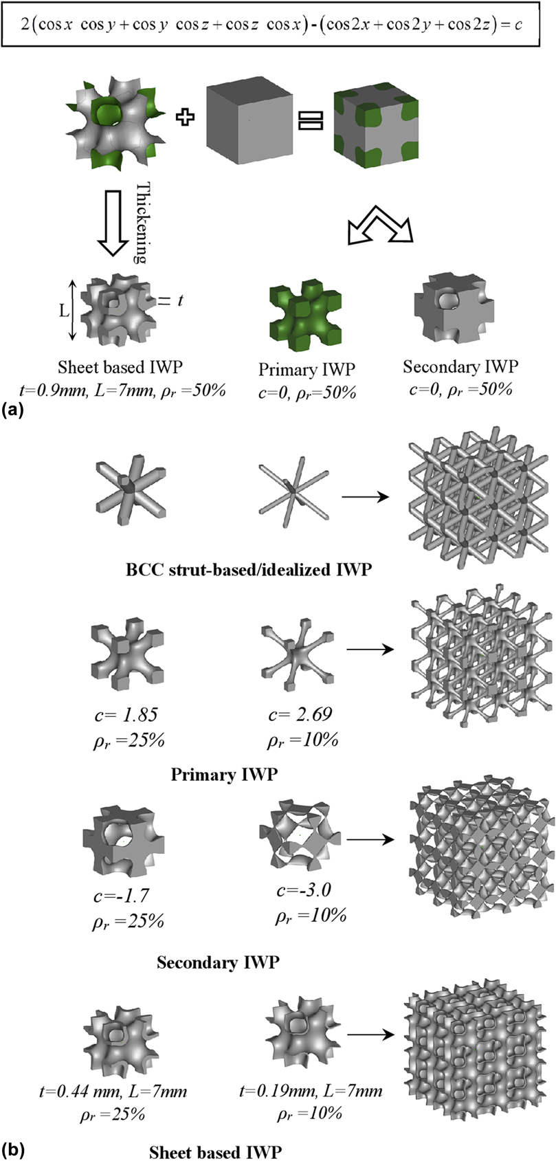
In general, metallic foams are stochastic and irregular in nature due to their fabrication techniques. In fact, these fabrication techniques are limited in their ability to fully control the internal morphology of the metallic foam, causing low repeatability of the morphology and, hence, uncertainties in the mechanical and physical properties. Despite the fact that they proved to be very reliable and mechanically robust in a large range of industrial and commercial applications, Reference Ashby, Evans, Fleck, Hutchinson, Wadley and Gibson12 the stochasticity results in overdesign driven mainly by high safety factor considerations. The high safety factor in design is considered to account for process-related defects and flaws resulting from the limited control over the topology. Reference Rashed, Ashraf, Mines and Hazell23 On the other hand, lattices are periodic cellular structures with well-defined internal architecture, making them more preferable than metallic stochastic foams in most cases. Examples of periodic lattice structures include prismatic structures such as honeycombs, and hollow or solid strut-based lattices such as the simple body centered cubic (BCC) structure shown in Fig. 1.
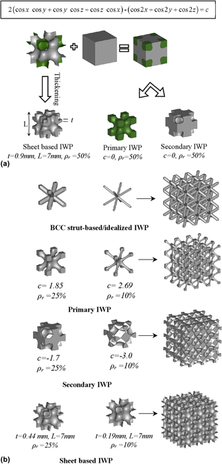
Designing periodic cellular structures. (a) Methods of creating periodic structures derived from the IWP minimal surface. The level set approximation equation is shown at the top. The constant c controls the relative density ρr of the corresponding skeletal-based cellular structure. In the case of sheet-based structure, the relative density is controlled by the assigned thickness t at a constant size L. (b) Low and high relative densities of the IWP-based structures.

The most used fabrication techniques for producing periodic lattice structures is the additive manufacturing (AM) technique, which ensures high levels of structural controllability, reproducibility, and design freedom. AM refers to the process of fabricating parts layer by layer, adding materials only where it is needed leading to considerable reduction in material usage as well as generated waste. For metallic lattice structures, selective laser sintering (SLS), selective laser melting (SLM), and selective electron beam melting are some of the commonly used AM techniques in which metallic powder is selectively melted or sintered using an energy source (laser or electron beam) to form a 3D structure. In these techniques, several metallic powders can be used to create architected lattice structures including aluminum, Reference Liu, Kamm, García-Moreno, Banhart and Pasini24,Reference Yan, Hao, Hussein, Bubb, Young and Raymont25 titanium, Reference Yan, Hao, Hussein and Young26 and steel alloys. Reference Yan, Hao, Hussein, Young and Raymont27,Reference Alsalla, Hao and Smith28
By employing AM, the topology-property relationship of architected materials has been a matter of rigorous research in the last decade. Starting with simple strut-based geometries Reference Brenne, Niendorf and Maier29,Reference Sing, Yeong, Wiria and Tay30 like the BCC structure, to more complex sheet-based, mathematically defined topologies. Reference Al-Ketan, Al-Rub and Rowshan10,Reference Al-Ketan, Soliman, AlQubaisi and Abu Al-Rub31–Reference Yoo35 For example, Brenne et al. Reference Brenne, Niendorf and Maier29 investigated the impact of microstructure and local strains on the monotonic and cyclic behavior of additively manufactured titanium-based BCC lattice structures under uniaxial and bending loading. They used digital image correlation to characterize local strains and observed structural weaknesses at low degrees of deformation and at an early stage of lifetime. Feng et al. Reference Feng, Tang, Liu, Liu and Setchi36 investigated the mechanical properties of BCC and modified BCC lattice structures made of titanium using the SLM technique and verified their results using a proposed analytical model. In a more specific and application-oriented study, extensive work has been done to identify the best topology that mimics the nature of human bone and provides a viable environment to recuperate and regenerate damaged tissue cells. Reference Wang, Xu, Zhou, Xu, Leary, Choong, Qian, Brandt and Xie37,Reference Giannitelli, Accoto, Trombetta and Rainer38 As such, several strut-based lattice structures with high levels of complexity have been vastly investigated. Reference Heinl, Müller, Körner, Singer and Müller13,Reference Ahmadi, Yavari, Wauthle, Pouran, Schrooten, Weinans and Zadpoor39–Reference Mullen, Stamp, Brooks, Jones and Sutcliffe43
To maximize the benefits of architecture and topology in tailoring the mechanical and physical properties of lattice materials, focus shifted toward structures with mathematically defined architectures. For example, triply periodic minimal surfaces (TPMSs) were used to create architected lattice structures for a wide range of applications. Reference Babaee, Viard, Wang, Fang and Bertoldi2,Reference Al-Ketan, Al-Rub and Rowshan10,Reference Al-Ketan, Soliman, AlQubaisi and Abu Al-Rub31–Reference Yoo35,Reference Ha, Vaia, Lynn, Costantino, Shin, Smith, Matsudaira and Thomas44–Reference Al-Ketan, Assad and Abu Al-Rub52 TPMSs are complex 3D topologies that locally minimize the surface area for a given boundary. These surfaces split the space into two or more interlocked domains, where each domain is a single connected and infinite component with no enfolded voids. TPMS-based structures can be created either by thickening the minimal surface to create sheet-based lattice structures or by solidifying the volumes enclosed by the minimal surfaces to create skeletal-based lattice structures. Reference Al-Ketan, Assad and Abu Al-Rub52
Although TPMSs have been discovered for more than a hundred years, their fabrication was challenging due to their topological complexity. Recent advances in AM techniques helped mitigating these challenges. Unlike strut-based lattice materials, TPMS-based lattice materials are known to have smoother transition at the connection points of several struts within the structure, which may result in less stress concentration and hence enhanced load-bearing capabilities. Several TPMS skeletal-based lattice structures have been studied for their printability and mechanical properties using a variety of metals. Reference Yan, Hao, Hussein, Bubb, Young and Raymont25–Reference Alsalla, Hao and Smith28 For example, the relationship between deformation mechanism and mechanical properties of additively manufactured TPMS skeletal-based lattice structures, namely, the IWP and Schoen's F-RD (FRD) were investigated, Reference Kadkhodapour, Montazerian, Darabi, Zargarian and Schmauder53 and the results showed that the stretching-dominated mode of deformation can be observed when the global orientation of struts was in line with the loading direction. In recent studies, the quasi-static and dynamic mechanical properties, and energy absorption of metallic TPMS sheet-based lattices were investigated. Reference Bobbert, Lietaert, Eftekhari, Pouran, Ahmadi, Weinans and Zadpoor32,Reference Han, Lee and Kang54,Reference Maskery, Aboulkhair, Aremu, Tuck and Ashcroft55 For quasi-static mechanical properties, the TPMS sheet-based porous biomaterials made of titanium alloy were tested for a range of relative densities between 23 and 47%. The results showed a favorable but rare combination of relatively low elastic properties in the range of those observed for trabecular bone and high yield strengths exceeding those reported for cortical bone. It was also found that permeability values measured for the developed biomaterials were in the range of those reported for trabecular bone. Reference Bobbert, Lietaert, Eftekhari, Pouran, Ahmadi, Weinans and Zadpoor32 Energy absorption investigations showed that the TPMS sheet-based gyroid structure made of aluminum alloy exhibited desirable specific energy absorption values. In fact, TPMS sheet-based structures are recently witnessing increased interest not only for their mechanical properties but also for other topology-related properties. Reference Abueidda, Dalaq, Abu Al-Rub and Younes50,Reference Abueidda, Dalaq, Al-Rub and Jasiuk51,Reference Elliott, Gray, McClay, Nassief, Nunnelley, Vogt, Ekong, Kardel, Khoshkhoo and Proaño56–Reference Sreedhar, Thomas, Al-Ketan, Rowshan, Hernandez, Abu Al-Rub and Arafat58 For example, in wastewater treatment and desalination applications, the high surface area to volume ratio, smooth-curved nature of TPMS structures, and enhanced turbulence made them a potential candidate for next generation moving bed bioreactors and feed spacers. Reference Elliott, Gray, McClay, Nassief, Nunnelley, Vogt, Ekong, Kardel, Khoshkhoo and Proaño56,Reference Sreedhar, Thomas, Al-Ketan, Rowshan, Hernandez, Abu Al-Rub and Arafat58 Also, in heat exchangers, the maze-like nature and interpenetrating volumes separated by a thin shell made these topologies desirable candidates for heat transfer applications. Reference Femmer, Kuehne and Wessling57 Thermal and electrical conductivities of TPMS-based structures were also investigated for interpenetrating phase composites. Reference Abueidda, Dalaq, Abu Al-Rub and Younes50
In this work, we investigate the architecture-property relationship associated with the possible configurations of using a TPMS to create periodic lattice structures. For this purpose, we use the IWP minimal surface Reference Cvijović and Klinowski59 to create skeletal-based and sheet-based lattice structures (see Fig. 1). The morphology of the IWP is defined using level set approximation equations. Reference Michielsen and Kole60 We used computer-aided design software to create the lattices and conducted finite element (FE) analyses to highlight the dependency of the mechanical properties on the exhibited architecture of the investigated lattice structures under ideal conditions. To obtain real experimental insights of the role of architecture on tuning the mechanical properties of the investigated lattice structures, we used the SLS technique to fabricate testing samples. A scanning electron microscope (SEM) was used to characterize the fabricated topologies and assess the quality of the 3D printing process. Finally, samples were tested mechanically and their compressive mechanical properties were deduced and discussed within the framework of cellular materials.
II. EXPERIMENTAL AND NUMERICAL METHODS
The IWP surface is a surface that splits the surrounding space into two domains with similar volumes and dissimilar topologies; these two domains are referred to as Primary IWP and Secondary IWP as shown in Fig. 1(a). To create skeletal-based IWP lattices, one of the two volumes is solidified and the second volume is considered as void or air. The relative density of each structure can be controlled by the constant c in the level set approximation equation as shown in Fig. 1(a). For the sheet-based IWP structure, the minimal surface is assigned a thickness that controls its volume and ultimately its relative density. In fact, the BCC strut-based structure resembles an idealized version of the more complex Primary IWP skeletal-based structure shown in Fig. 1(b). Both structures can be described as solid members running through the diagonals of a cube and intersecting in the middle point. In what follows, the term BCC strut-based structure and idealized IWP will be used interchangeably.
FE simulations were carried out to investigate the effect of architecture on uniaxial elastic modulus and yield stress of lattices for ideal cases where process-induced imperfections are avoided, and the material is assumed to be isotropic. For that purpose, CAD files were generated and imported into the FE software, Abaqus. An elastic–perfectly plastic constitutive material model was considered with the Young’s modulus of 180 GPa and a Poisson’s ratio of 0.3. The yield stress was set to 1000 MPa. These values are consistent with the material properties of the base powder used to fabricate the experimental samples. Simulations were conducted by applying mixed boundary conditions on single unit cells Reference Li61 with the displacement-controlled loading mode. In fact, it was previously concluded that mixed boundary conditions can be used to obtain the effective properties of lattice materials. Reference Abueidda, Dalaq, Abu Al-Rub and Younes50,Reference Dalaq, Abueidda, Abu Al-Rub and Jasiuk62 This approach is well described by Jiang et al. Reference Wang, Feng and Jasiuk63 and used by Khaderi et al. Reference Khaderi, Deshpande and Fleck64 to investigate the plastic yield properties of the gyroid truss-based lattice. Tetrahedral mesh was generated, and the mesh was refined until stresses converged, with a final average mesh size of approximately 100,000 elements.
For the purpose of mechanical testing, the considered lattice structures were fabricated using gas atomized maraging steel fine powder. This class of steel is an ultrahigh strength steel material commonly used for many tooling applications such as tools for injection molding, die casting of light metal alloys, and also for high performance industrial and engineering parts. The chemical composition of the maraging steel powder can be found in Table I.
Chemical composition of maraging steel.

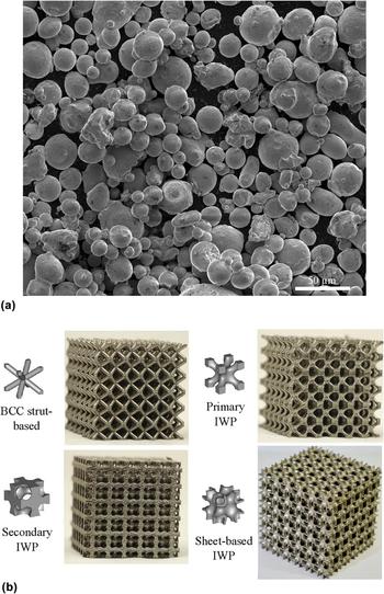
Figure 2(a) shows the SEM image of the maraging alloy powder. The powder used has a nearly spherical shape with smooth surfaces. The powder particle size is in the range of 5–50 µm. The Young’s modulus, yield strength, and ultimate strength of sintered powder are 180 GPa ± 20 GPa, 1000 MPa ± 100 MPa, and 1100 MPa ± 100 MPa, respectively, as reported in the data sheets of the powder supplier. The SLS system EOSINT M280 machine supplied by EOS GmbH, Munich, Germany, was used to fabricate the designed samples. In SLS, every new layer is first scanned by a contour laser track followed by a hatching laser track. An alternating hatching pattern strategy was adapted such that the direction of hatching was continuously rotated between successive layers. Samples consisted of a 6 × 6 × 6 unit cell of 7 mm in size patterned in 3D space. Each cubic sample has a side length of 42 mm. Printed samples are shown in Fig. 2(b).
AM–SLS technique was used to fabricate the lattice structures. (a) SEM image showing the size and shape distribution of the maraging steel powder used in the SLS process. (b) 3D-printed IWP-based lattices.

After fabrication, the SEM was used to assess the quality of printing. Then, the samples were tested in compression using the Instron and MTS testing machines under displacement-controlled compression with a compressive strain rate of 0.001/s. The samples were tested in a direction perpendicular to the printing direction, and the load was measured with 100 kN (Instron, Norwood, Massachusetts) and 300 kN (MTS Systems Corporation, Eden Prairie, Minnesota) load cells. Specimens were positioned in the center of the loading frame to ensure uniform loading and eliminate moments induced by specimens’ misalignments. The test was stopped when the recorded force reached 98 kN (Instron, Norwood, Massachusetts) or 285 kN (MTS Systems Corporation, Eden Prairie, Minnesota) or if densification is reached. It is worth mentioning that several samples were tested using both testing machines and the results were very similar.
III. RESULTS AND DISCUSSION
A. Numerical simulations
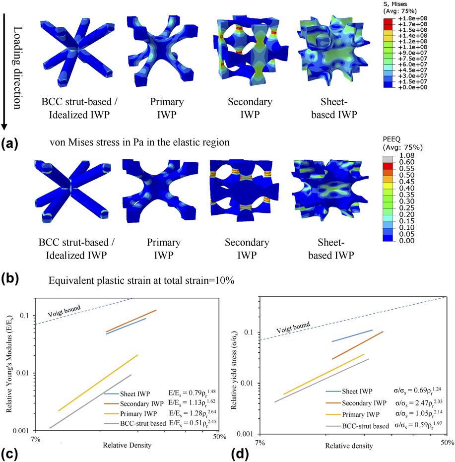
We simulated the uniaxial elastic–plastic response of the different lattice structures at different relative densities. For example, the von Mises stress distributions for the investigated lattices are shown in Fig. 3(a) for 15% relative density. As expected, idealized IWP shows more stress concentration as compared to Primary IWP at the connecting nodes. The smooth transition in the strut members of the Primary IWP causes reduction in stress concentration resulting in enhancement in the load-bearing capabilities of the structure. Secondary IWP shows the highest stress values. This is attributed to the fact that struts are aligned parallel to the loading direction. It can be noted that each strut of the Secondary IWP is oriented by 90° with respect to its neighbor and struts are connected via narrow nodes. The diameter of these narrow nodes increases as the relative density increases. These narrow nodes experience large stress concentration when their corresponding struts are aligned parallel to the loading direction as observed in Fig. 3(a). The sheet-based IWP shows the highest stress distribution among the investigated lattices. This is attributed to the fact that this structure is free of connecting nodes or sharp edges. Therefore, the sheet-IWP shows the best stress transferring capabilities. These contours show locations where damage may initiate.
Numerical simulations conducted for the different investigated lattice structures. (a) von Mises stress in the elastic region, (b) equivalent plastic strain at total strain = 10%, (c) numerically obtained relative Young’s modulus as a function of the relative density, and (d) numerically obtained relative yield stress as a function of the relative density.

Figures 3(c) and 3(d) show, respectively, the computed effective (macroscopic) Young’s modulus and initial yield stress, normalized by the corresponding base material’s modulus E
S and yield strength σS, as a function of the relative density ρr. The results are fitted with power scaling laws
 $E{\rm{/}}{E_{\rm{S}}} = A\rho _{\rm{r}}^n$
and
 $\sigma {\rm{/}}{\sigma _{\rm{S}}} = B\rho _{\rm{r}}^m$
, where A and B are geometric-dependent parameters, which are controlled here by the preferred loading direction. Values of A = B = 1 and n = m = 1 correspond to the Voigt bound that represents the maximum theoretical effective stiffness or strength for any cellular structure. As anticipated, the Primary IWP lattice structure has a higher stiffness compared to the BCC strut-based, but comparable power-law exponents indicate that both have almost similar deformation modes. However, the sheet-based IWP and Secondary IWP have stiffness values that are significantly higher than those of the Primary IWP and BCC strut-based lattices, and they have comparable power-law exponents, indicating an almost similar deformation mechanism. Both Secondary and Primary IWPs have the highest and comparable geometric parameters A, indicating that both are loaded more closely to their corresponding preferred loading directions as compared to both BCC strut-based and sheet-based IWPs. Ideally, it can be seen that the stiffness of the Secondary IWP is slightly higher than that of the sheet-based IWP, especially at higher relative densities. On the other hand, the sheet-based IWP shows the highest yield stress values, followed by the Secondary IWP, the Primary IWP, and finally the BCC strut-based structure. The secondary IWP, Primary IWP, and BCC strut-based cellular structures have comparable power-law exponents, indicating almost a similar yielding (or failure) deformation mechanism. The Secondary IWP has the largest geometric parameter B since it is loaded in the strongest direction, whereas BCC strut has the lowest B. All these computational results show the dominant effect of the cellular architecture on stiffness and strength. The effect of cell cubic symmetry has been investigated for sheet-based IWP assuming linear elastic behavior by Abueidda et al.
Reference Abueidda, Abu Al-Rub, Dalaq, Lee, Khan and Jasiuk47
in which the independent elastic constants (uniaxial, shear, and bulk moduli) have been estimated and elastic anisotropy has been assessed. However, in this work, our focus was only on the uniaxial behavior and as such the uniaxial elastic and yield stress have been estimated to explain some of the experimental results. Moreover, the authors are currently working on fully investigating the anisotropic elastic and yield behavior of these lattices along the lines of the work in Lee et al.
Reference Lee, Khan and Abu Al-Rub65
It is worth mentioning that bifurcation can occur anytime and the onset of nonlinearity can be triggered by buckling rather than yielding. Bifurcation can be investigated through carrying out simulations on fully detailed lattices or representative volume elements,
Reference Vigliotti, Deshpande and Pasini66
or using a single unit cell following the approach and boundary conditions proposed by Valdevit et al.
Reference Valdevit, Godfrey, Schaedler, Jacobsen and Carter67
to determine the local buckling of the lattices. The approach proposed by Valdevit et al.
Reference Valdevit, Godfrey, Schaedler, Jacobsen and Carter67
has been followed by Abueidda et al.
Reference Abueidda, Bakir, Al-Rub, Bergström, Sobh and Jasiuk49
to address the issue of bifurcation in 3D-printed polymeric lattices with sheet-based TPMS topologies and concluded that lattices with thinner walls (relative densities below 2.5%) are governed by buckling, while those associated with thicker walls (relative densities higher than 2.5%) are governed by plastic yielding.
B. Microstructural characterization
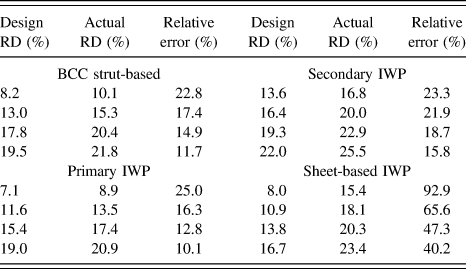
For the purpose of mechanical testing, samples were fabricated using the EOSINT M280 SLS 3D printer (EOS GmbH, Munich, Germany). The as-built samples were air weighted, and the actual relative density was calculated. Designed and actual relative densities as well as the relative error are reported in Table II. Samples showed the deviation between the design and the actual printed relative density; this deviation decreases with increasing designed relative density. Sheet-based IWP samples showed the highest deviation from the design, considerably larger than the other lattice structures. This can be stringently related to the surface area of the unit cell. In fact, the surface area of the sheet-based IWP is much higher than that of the skeletal-based IWP and the BCC strut-based structures. As the surface area of the part increases, the contact area between the powder bed and the hot-sintered layer increases. The hot-sintered layer causes partial fusion of the loose powder laying below it, and the partially fused powder bonds to the sintered layer adding more weight to the final sample. This added weight contributes to the total weight of the sample, which affects the actual measured relative density. Also, the melt pool size of the contour track can be larger than the laser spot size, resulting in oversizing in the sintered part. Although the scan vectors of the contour track are usually shifted inward to compensate for this possible deviation, Reference Van Bael, Kerckhofs, Moesen, Pyka, Schrooten and Kruth68 it is still not enough to obtain the required precision.
Designed versus actual relative densities of the cellular structures.

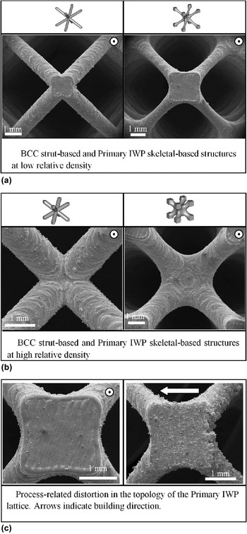
In Fig. 4, SEM images for BCC strut-based and Primary IWP structures are shown at low and high relative densities. It can be observed that the intersection between struts has a smoother transition in the case of Primary IWP as compared to the BCC strut-based lattice structure. Also, Fig. 4(c) shows process-related distortion in the topology of the Primary IWP lattice. Since the powder bed supports the structure during its layer-by-layer build-up, we see more traces of the molten powder at the downward facing surfaces than on the upward facing surfaces along the printing direction. It can be observed that the amount of the powder that bonds to lattice’s downward facing surfaces increases with decreasing the angle between the sintered layer and the horizontal direction. Horizontal surfaces are laying completely over the powder bed causing the highest interaction with the powder as can be observed in Fig. 4(c). Process-related imperfections are inevitable when fabricating lattices using AM techniques. Reference Bagheri, Melancon, Liu, Johnston and Pasini69 Several recent studies investigated the origin of these imperfections and how they relate to the overall mechanical properties of the fabricated samples. For example, Liu et al. Reference Liu, Kamm, García-Moreno, Banhart and Pasini24 used X-ray computed tomography to capture process-induced defects and studied their effect on the overall mechanical properties of 3D-printed metallic octet and rhombicuboctahedron lattice structures. Their results showed that geometric imperfections can cause failure mode transitions not visible in defect-free lattices. The effect of building orientation and heat treatments on the microstructure and mechanical properties of 3D-printed Ti6Al4V lattice structures were investigated by Wauthle et al. Reference Wauthle, Vrancken, Beynaerts, Jorissen, Schrooten, Kruth and Van Humbeeck70 Their results show a significant decrease in mechanical strength for samples that are built diagonally. Fogagnolo et al. Reference Sallica-Leva, Jardini and Fogagnolo71 studied the effect of laser energy inputs on the microstructure and the mechanical properties of Ti6Al4V 3D-printed lattices. Their results showed that the use of high-energy input parameters resulted in better mechanical properties. In general, material and geometric imperfections observed in the as-built lattices strongly influence their elastic response and failure mechanism.
SEM images of BCC strut-based and Primary IWP skeletal-based structures at (a) low and (b) high relative densities. (c) shows the distortion in the topology as a function of the building direction.

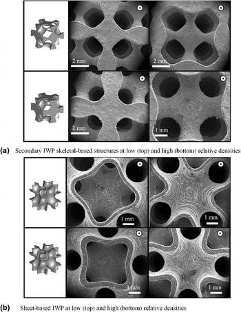
Figure 5 shows the SEM images of the Secondary IWP structure and sheet-based IWP at high and low relative densities. It should be noted that employing the IWP minimal surface to create skeletal-based structures is limited by connectivity of the structure at a certain relative density. For example, the relative density of the Secondary IWP is limited to a minimum design value of 13%, and below this relative density, the unit cell loses its structural integrity. This also applies to the Primary IWP, which is limited to a 7% minimum theoretical relative density. On the other hand, the relative density of the sheet-based IWP is controlled by the assigned thickness, and therefore, the achievable relative density is only limited by the fabrication capabilities of the SLS system. The minimum achievable thickness is controlled by the laser power, pool melt size, and particle size. For the system used in this work, the minimal achievable thickness ranges between 200 and 250 µm.
SEM images showing 3D printed structures at high and low relative densities for (a) Secondary IWP skeletal-based structures and (b) sheet-based IWP. Arrows indicate the building direction.

C. Mechanical testing
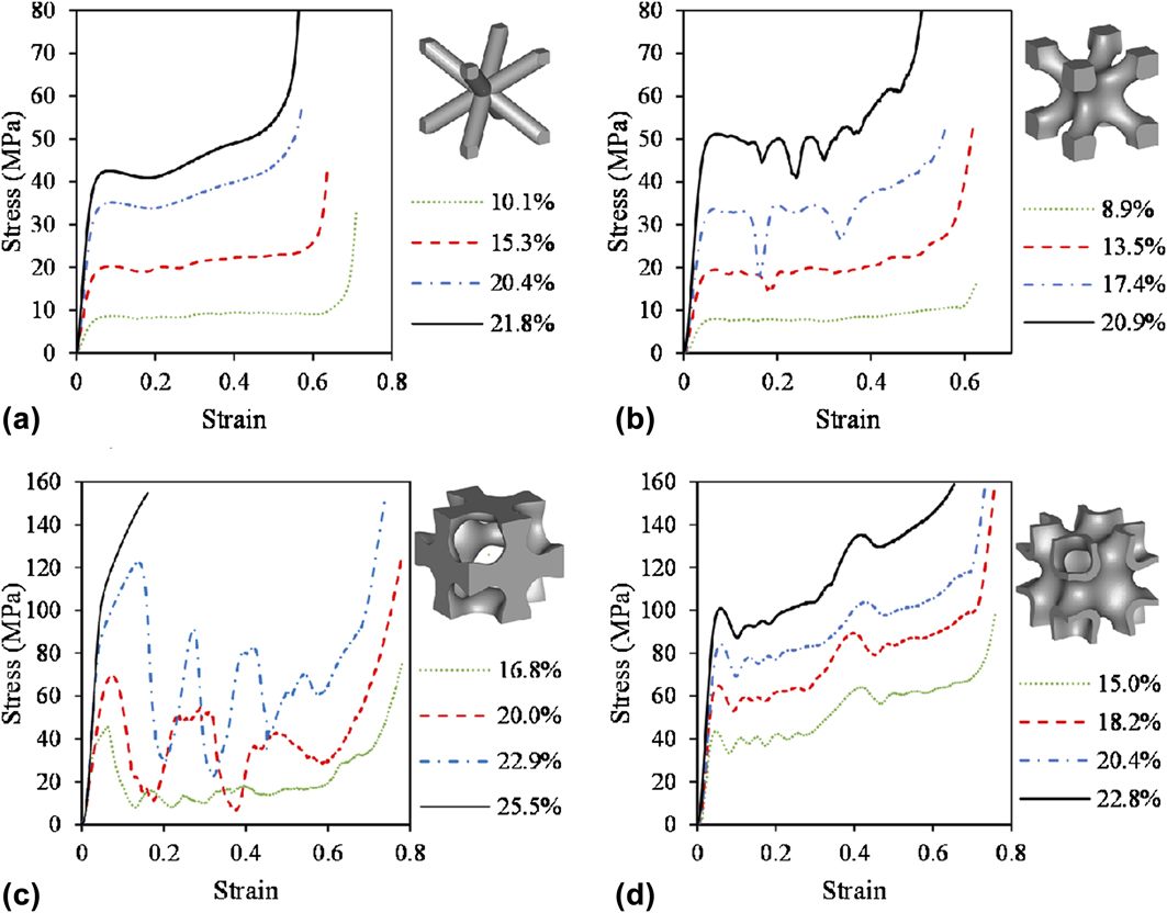
The fabricated samples were tested in compression perpendicular to the printing direction, and stress–strain responses were extracted and presented in Fig. 6. For each cell topology, we present the stress–strain responses for the different relative densities in the same figure; therefore, four stress–strain diagrams are shown for each architecture, respectively. In general, the overall mechanical properties increase with increasing the relative density for each cell topology. A slight nonlinearity was observed at the very early stages of the stress–strain curve due to possible misalignment of the sample and testing plates. However, this nonlinearity did not affect the overall mechanical properties, and repeating the test showed very high repeatability in the stress–strain response. Each stress–strain curve shows four distinct regions: first, the stress increases linearly as a function of strain indicating the elastic regime where the slope of the linear curve represents the Young’s modulus. The second region starts when the stress–strain curve departs from the linear response and enters the nonlinear regime; stress keeps increasing until it hits the highest value denoting the maximum or peak stress. After the peak stress is reached, samples start to show evidence of deformation reflected as a softening behavior in the stress–strain curve. The third region is the plateau stress regime where deformation keeps evolving until the failure of all the cells in the structure. The shape of the plateau stress is different for different cell topologies. The idealized IWP (i.e., BCC strut-based) exhibits a nearly constant plateau trend where the stress remains constant with increasing strain, especially at low relative densities. The slope of the plateau region shows a slight increase with increasing the relative density of the structure. A similar trend can be observed in the plateau stress exhibited by the Primary IWP; however, small fluctuations are observed in the curves, especially at high relative densities indicating failure incidents. These fluctuations are more severe in the case of the Secondary IWP where a dramatic drop in the stress–strain response is witnessed after the peak stress is reached. This behavior is more pronounced at higher relative densities. At a relative density of 25.5%, the stress–strain curve reached the maximum capacity of the load cell before proceeding to the plateau stress region and tests were stopped. The stress–strain response of the sheet-based IWP showed less fluctuation in the plateau region; however, the slope of the plateau stress was increasing as a function of the applied strain showing a linear hardening response. After the plateau region, samples start densifying and stress–strain curves start to rise intensely, denoting the densification stage.
Compressive stress–strain responses of the IWP-based cellular structures. (a) Idealized IWP (BCC strut-based), (b) Primary IWP, (c) Secondary IWP, and (d) sheet-based IWP.

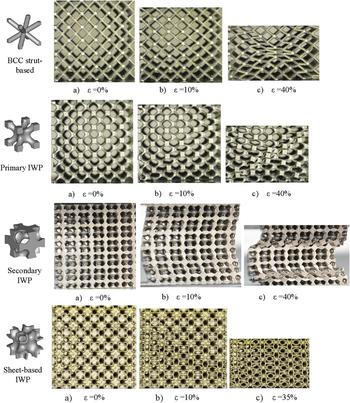
The nature of deformation of the investigated IWP-based structures varies depending on the cell topology. In Fig. 7, we present deformation patterns captured during testing at different strain levels. It is worth mentioning here that the relative density at which these deformation patterns are captured varies from one cell topology to the other. However, for the same cell topology, the observed deformation mechanism was the same for all the considered relative densities. Hence, this deformation mechanism is independent of the relative density and is highly dependent on the cell topology. In general, three main deformation mechanisms can be observed: (i) the formation of shear bands right after the peak stress. This deformation mechanism is observed in the idealized IWP and Primary IWP. After the formation of the first shear band, layers start to fail diagonally following this shear band, and in some cases, a double-shear band can be observed. In the idealized IWP and Primary IWP, the load-bearing strut members are inclined 45° relative to the loading direction and are subjected to bending loads. Also, the nonzero friction between the specimen and the loading platens results in hindering the lateral expansion of the sample; hence, lateral compressive stresses are expected to build up. As such, the loaded strut members are expected to bend and rotate around their nodes, leading to shear mode failure. It must be noted that the formation of shear bands in lattice structures is commonly observed even for lattices having higher geometrical complexity than the BCC and Primary IWP. Reference Bobbert, Lietaert, Eftekhari, Pouran, Ahmadi, Weinans and Zadpoor32,Reference Feng, Tang, Liu, Liu and Setchi36,Reference Kadkhodapour, Montazerian, Darabi, Zargarian and Schmauder53,Reference Wauthle, Vrancken, Beynaerts, Jorissen, Schrooten, Kruth and Van Humbeeck70,Reference Qiu, Yue, Adkins, Ward, Hassanin, Lee, Withers and Attallah72 It is usually attributed to the presence and distribution of defects as well as the constituent’s material and testing conditions. (ii) The second observed deformation mechanism is the buckling of the structure as can be observed in the case of the Secondary IWP, which is followed by the collapse of unit cells at connection points between struts. The overall buckling of the structure is related to the fact that some strut members are aligned axially and parallel to the loading direction. Upon further loading, the overall buckling of the structure changes the alignment of the struts with respect to the loading direction. This structural reconfiguration results in subjecting struts to eccentric loading. As a result, deformation starts to take place at weak strut intersections where nodes are subjected to the highest strain localization as shown in the numerical simulations [Figs. 3(a) and 3(b)], leading to complete failure at these connection sites. Finally, (iii) the deformation of the sheet-based IWP where the structure deforms collectively such that every layer deforms in the same way its neighbors are deforming. Although it can be observed that at 10% strain some unit cells are more distorted than others, the structure tends to fail collectively upon further loading. This collective deformation can be attributed to the distribution of equivalent plastic strain observed in Fig. 3(b).
Deformation of the IWP-based cellular structures at different strains under compression.

In general, the mechanical properties of macroscopic cellular metals are a function of the relative density, the solid constituent, and the unit cell architecture. When subjected to a macroscopic loading, the structure follows a stretching- or bending-deformation mode.
Reference Deshpande, Ashby and Fleck73
In a stretching-dominated deformation mode, the stiffness of cellular structures scales linearly as a function of the relative density and is higher than that of a bending-dominated deformation mode that scales quadratically with the relative density. On the other hand, the toughness of a bending-dominated deformation is generally larger than that in the case of stretching-dominated deformation mode.
Reference Deshpande, Ashby and Fleck73
For strut-based lattice structures, the Maxwell criterion
Reference Maxwell74
can be used to judge whether the structure will follow a bending-dominated or stretching-dominated mode of deformation. A lattice may be considered to be a pin-jointed truss consisting of a number of interacting struts s and nodes j, and the Maxwell criterion can be defined as Z = s − 3j + 6 for 3D lattices. For Z < 0, a bending-dominated mode is favored, and for Z ≥ 0, a stretching-dominated mode is favored.
Reference Mazur, Leary, Sun, Vcelka, Shidid and Brandt75
For sheet-based lattices, the Gibson–Ashby model
Reference Gibson and Ashby76
can be used to determine the mode of deformation. Although TPMS sheet-based lattice structures have an interconnected network of voids, they might still be simplified and approximated as closed cell foams. The Gibson–Ashby model developed for the relative elasticity of closed cell foams is described as
 ${E_{{\rm{cellular}}}} = {\beta _1}{\varphi ^2}\rho _{\rm{r}}^2 + {\beta '_1}\left( {1 - \varphi } \right){\rho _{\rm{r}}}$
, where E
cellular is the Young’s modulus of the cellular structure, β1 and
 ${\beta '_1}$
are constants, and φ is a nondimensional parameter that describes the ratio of solid materials contained in the cell edges to the total solid material contained in both the cell edges and the cell faces. This nondimensional parameter can be described as φ = t
2/(t
2 + bL), where L is the unit cell length, t is the thickness of the edge (strut), and b is the thickness of the sheet. These length parameters are shown in Fig. 8(a), where a representation of the open cell and closed cell foams is provided.
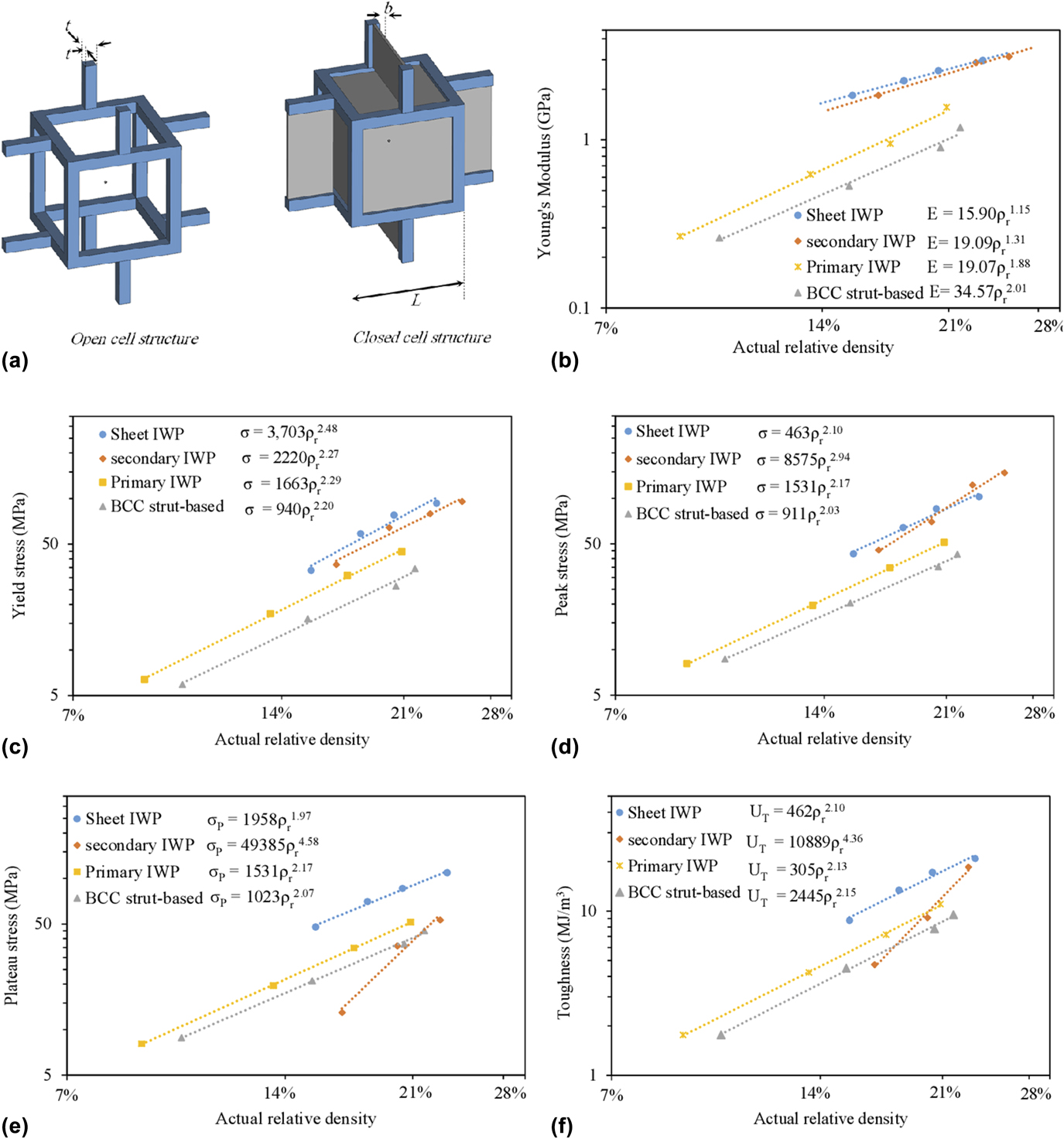
Compressive mechanical properties as a function of the actual relative density for the tested IWP-based cellular structures. (a) Gibson–Ashby representation of open cell and closed cell foams, (b) Young’s modulus, (c) yield stress, (d) peak stress, (e) plateau stress, and (f) toughness.
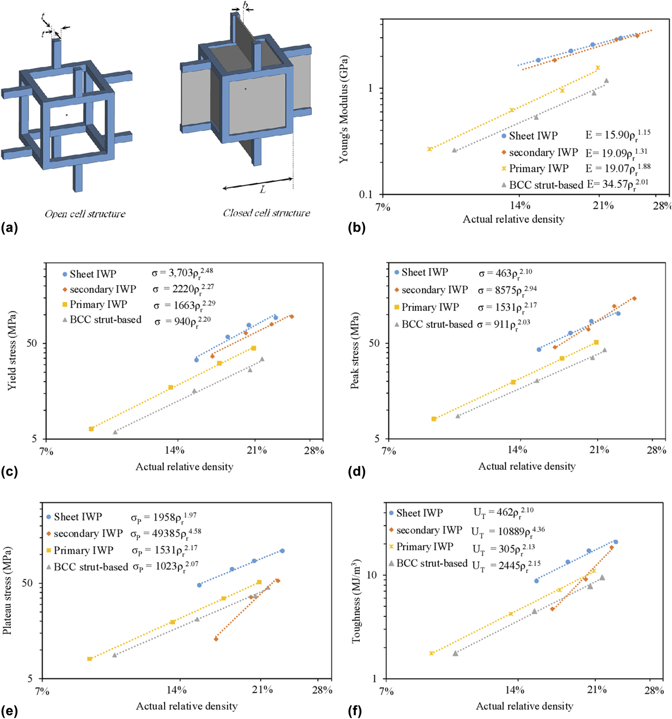
To quantify and compare the mechanical behavior of the different topologies, the mechanical properties (i.e., Young’s modulus, yield stress, peak stress, plateau stress, and toughness) were extracted from the stress–strain responses and plotted against the relative density in log–log scale graphs in Fig. 8(b) through Fig. 8(e). Maximum stress (peak stress) is determined from the first peak in the stress–strain curve. Plateau stress is calculated as the average stress for the values of strain between 20 and 40%, and toughness is measured as the area under the stress–stain curve up to a 25% strain. The data point for the different cell topologies in Fig. 8 was fitted using a power law in the form of
 ${\phi _{{\rm{cellular}}}} = \alpha \rho _{\rm{r}}^n$
, where ϕcellular is the mechanical property of the cellular structure, ρr is the relative density, and α and n are the fitting constants. The fitted parameters are presented in the same figure. From the fitted values of Young’s modulus and yield strength, it can be noticed that the idealized IWP and Primary IWP show comparable n values, both exhibiting a bending-dominated behavior with n values close to 2, which qualitatively agrees with the numerical results. In fact, according to the Maxwell criterion, both structures have 8 struts and 9 joints, which result in a Z value of −13, which favors a bending-dominated mode of deformation. The Primary IWP shows higher mechanical properties than the idealized IWP, and this can be strictly related to the modified topology that minimized the stress concentration effect and increased the load-bearing capabilities as anticipated before. On the other hand, both the Secondary IWP and the sheet-based IWP show higher stiffness values than the Primary and idealized IWPs and exhibit a near stretching-dominated behavior with n values close to 1. In fact, the sheet-based IWP has partially filled walls that contribute to cell stiffening, and if it is approximated as a closed cell foam, then the Gibson–Ashby model can be applied to give insights about its favored mode of deformation. In this case, we can assume that the sheet thickness and strut thickness are equal (i.e., b ≈ t) and since L ≫ b, L ≫ t, φ → 0 and the Gibson–Ashby model reduces to
 ${E_{{\rm{cellular}}}} = {\beta '_1}{\rho _{\rm{r}}}$
where a linear relation between the Young’s modulus and the relative density can be deduced. In fact, Vigliotti et al.
Reference Vigliotti and Pasini77
investigated the effect of adding walls to strut-based cellular structures and concluded that the in-plane forces of the walls effectively contribute to the stiffness and yield strength of the lattice. Furthermore, their study showed that open cell topologies that are bending-dominated will behave as stretching-dominated if walls are added. While the Gibson–Ashby model is simplified and more general, numerical simulations gave a more specific representation. At this point, one can note the difference in the values of the fitted parameters for the simulated and tested samples. For example, the values of the n exponent obtained numerically indicate a mixed mode of deformation rather than a stretching-mode for the sheet-based IWP and Secondary IWP. In fact, this difference is related to several factors, for example, process-induced anisotropy in the tested samples. In the performed numerical simulations, we assumed a fully isotropic, defect-free material. However, the printing process and complexity of the structure can introduce several defects that can locally alter the mechanical properties of the base material. Also, printing parameters (i.e., laser power, scanning vectors, layer thickness, and scanning speed) have a large impact on the local microstructure and properties of the constituent material as already extensively discussed in previous studies.
Reference Liu, Kamm, García-Moreno, Banhart and Pasini24,Reference Brenne, Niendorf and Maier29,Reference Feng, Tang, Liu, Liu and Setchi36,Reference Arabnejad, Johnston, Pura, Singh, Tanzer and Pasini41,Reference Qiu, Yue, Adkins, Ward, Hassanin, Lee, Withers and Attallah72,Reference Mazur, Leary, Sun, Vcelka, Shidid and Brandt75,Reference Kadkhodapour, Montazerian, Darabi, Anaraki, Ahmadi, Zadpoor and Schmauder78,Reference Kempen, Yasa, Thijs, Kruth and Van Humbeeck79
Another factor that contributes to the discrepancy between numerical simulations and experimental results is the assumption that the contact between the loading platens and tested sample is a frictionless contact. In this study, numerical simulations were performed to address the ideal behavior of the different lattices rather than capturing the experimental behavior.
Figure 8(c) shows the yield stress as a function of the relative density of the tested samples. The sheet-based IWP lattice exhibits the highest values of yield stress followed by the secondary IWP. According to the experimental n exponent values, upon yielding and reaching the peak stress, both the sheet-based and Secondary IWPs switch to a bending-dominated deformation behavior driven by local sheet bending in the case of sheet-based IWP and global buckling of the whole structure in the case of Secondary IWP (see Fig. 7). This is in agreement with the numerical results in Fig. 3(d) for the Secondary IWP but not for the sheet-based IWP, which numerically shows a stretching-dominated behavior upon yielding. As emphasized earlier, the discrepancy between the experimental and numerical yielding results for the sheet-based IWP could be attributed to defects during fabrication, which mainly affects the yielding and failure mechanisms. The Primary IWP exhibited higher yield stress values as compared with the BCC strut-based lattice. In the case of plateau stress and toughness, the Secondary IWP exhibits the poorest behavior at low relative densities but enhances with increasing the relative densities to reach values comparable to the other topologies. This is attributed to the fact that the nodes connecting strut members get smaller and weaker at low relative densities, which reduces the load-bearing capabilities significantly and consequently leads to deformation dominated by progressing global and local buckling and catastrophic failure. Overall, the sheet-based IWP structure showed the best mechanical properties among the tested samples.
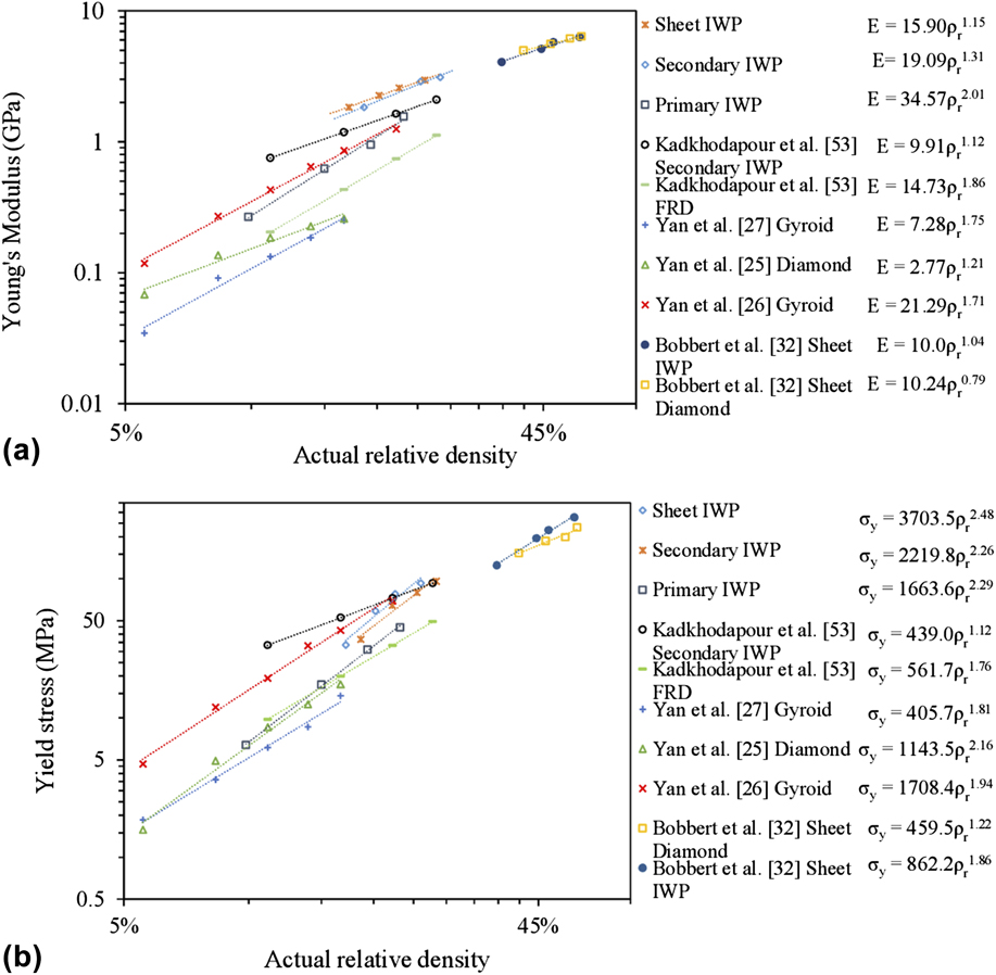
To compare the mechanical behavior of the investigated structures with other TPMS-based lattices, we plotted the Young’s modulus and yield stress as a function of relative density for several TPMS-based structures studied in the literature as shown in Figs. 9(a) and 9(b), respectively. Yan et al. investigated the mechanical properties of skeletal-gyroid and skeletal-diamond TPMS-based structures made of several base materials, namely, aluminum alloy, Reference Yan, Hao, Hussein, Bubb, Young and Raymont25 titanium alloy, Reference Yan, Hao, Hussein and Young26 and 316L stainless steel. Reference Yan, Hao, Hussein, Young and Raymont27 Kadkhodapour et al. Reference Kadkhodapour, Montazerian, Darabi, Zargarian and Schmauder53 investigated the mechanical behavior of Secondary IWP and FRD lattice structures made of titanium alloy, and Bobbert et al. Reference Bobbert, Lietaert, Eftekhari, Pouran, Ahmadi, Weinans and Zadpoor32 studied the mechanical properties of sheet-based TPMS IWP and diamond lattices made of titanium alloy. Overall, sheet-based cellular structures exhibit higher Young’s modulus as compared to other skeletal- and strut-based lattices. In general, these sheet-based structures show a stretching-dominated behavior in terms of stiffness. It is worth noticing that the n scaling exponent for the stiffness and yield stress of the sheet-based IWP investigated in this study and that in the work of Bobbert et al. Reference Bobbert, Lietaert, Eftekhari, Pouran, Ahmadi, Weinans and Zadpoor32 are slightly different but qualitatively in agreement where both show a stretching-dominated stiffening behavior and bending-dominated yielding behavior. This slight discrepancy can be attributed to the change in the range of investigated relative densities, base materials, printing parameters, and testing environment as well. In fact, Bobbert et al. Reference Bobbert, Lietaert, Eftekhari, Pouran, Ahmadi, Weinans and Zadpoor32 reported that a change in the n value can be observed if samples were tested with or without using lubricant between testing plates and the samples. The n scaling stiffness exponents for the Secondary IWP from this study and that by Kadkhodapour et al. Reference Kadkhodapour, Montazerian, Darabi, Zargarian and Schmauder53 are slightly different and show a stretching-dominated stiffening behavior, where the stiffness is higher in this study than that by Kadkhodapour et al. Reference Kadkhodapour, Montazerian, Darabi, Zargarian and Schmauder53 within the same range of relative densities. On the other hand, the n scaling yield stress exponents from this study and that by Kadkhodapour et al. Reference Kadkhodapour, Montazerian, Darabi, Zargarian and Schmauder53 are very different showing that the Secondary IWP continues to exhibit a stretching-dominated yielding behavior in the work of Kadkhodapour et al. Reference Kadkhodapour, Montazerian, Darabi, Zargarian and Schmauder53 and a switch to a bending-dominated behavior in the current study. Again, this difference in yield behavior can be attributed to variation in fabrication parameters and difference in the constituent’s material properties. Yan et al. investigated the behavior of the skeletal-gyroid lattice structure made of titanium Reference Yan, Hao, Hussein and Young26 and AlSi10 Mg alloy Reference Yan, Hao, Hussein, Bubb, Young and Raymont25 ; their results show comparable n exponents. While this comparison shows the superiority of the sheet-based structures over other strut-based lattices, a more robust comparison can be made by fixing the printing parameter, the base material, and the range of the relative densities studied.
Property chart showing the Young’s modulus and yield stress of the investigated IWP-based lattice structures with other TPMS-based lattices. (a) Young’s modulus and (b) yield stress.

This study presents the experimental evidence of the robustness and suitability of the sheet-based IWP structure for different applications where strong and lightweight materials with exceptional absorption capabilities are required.
IV. CONCLUSIONS
In summary, we designed and fabricated lattice structures with complex topologies based on the TPMS IWP for the purpose of investigating their topology-property relationship. The samples were fabricated using the SLS technique, and maraging steel was used as the base material. Printing quality was assessed using SEM. The fabricated samples were tested in compression, and their mechanical properties have been deduced from the corresponding compressive stress–strain responses. Experimental results showed that both the Secondary IWP and the sheet-based IWP cellular structures exhibited a near stretching-dominated stiffness deformation behavior, while the idealized IWP and Primary IWP showed a bending-dominated behavior, which is in agreement with FE results. This work presents the possible strategies that can be used to create TPMS IWP-based architected lattice structures, and highlights the role of employing such structures in controlling the mechanical properties of lattice materials. The highly complex sheet-based IWP showed stiffness and strength values that can reach more than twice the values obtained for strut-based and skeletal-based lattice structures, showing higher structural efficiency.
ACKNOWLEDGMENTS
The first and third authors acknowledge the financial support provided by Masdar Institute. The experimental parts were printed using Core Technology Platform resources at NYU Abu Dhabi. We thank Khulood Alawadi for assistance with 3D printing. The authors would also like to thank Alia Abu Ali for helping in designing the BCC lattice structures and Dr. Kamran Khan from Khalifa University of Science, Technology and Research for helping in testing the samples.