Introduction
The earliest leaky-wave antenna (LWA) was a slotted rectangular waveguide structure, manufactured in the 1940s [Reference Jackson, Baccarelli, Burghignoli, Fuscaldo, Galli and Lovat1]. So far, LWAs have experienced considerable development and made some breakthrough progress [Reference Nishida2–Reference Oliner, Jackson and Volakis5]. LWAs evolved from the original rectangular waveguide to the planar transmission line [Reference Luxey and Laheurte6–Reference Xu, Hong, Tang, Kuai and Wu8], and more new forms of LWAs have appeared in recent years due to the emergence of metamaterials [Reference Caloz, Itoh and Rennings9–Reference Tadesse, Acharya and Sahu11]. LWAs have been favored by researchers because of their features such as frequency sweep, low profile, high gain, and simple feeding network. With the rapid progress of communication technology, microwave electronic circuits are developing toward miniaturization and high integration, which presents a new challenge to LWAs.
Substrate-integrated waveguide (SIW) technology was first proposed by Wu et al. in 2001 and widely used in millimeter-wave-integrated circuits, thanks to its properties such as low profile, low loss, and easy integration [Reference Deslandes and Wu12–Reference Bozzi, Georgiadis and Wu15]. Subsequently, a significant number of research studies have been carried out on SIW-based LWAs [Reference Junfeng, Wei, Hongjun, Zhenqi and Ke16–Reference Karmokar, Chen, Thalakotuna, Qin, Bird and Guo26]. Forward scanning of the beam is achieved by etching transverse slots on the upper surface of the full-mode SIW [Reference Liu, Jackson and Long17–Reference Xu, Guan, Zhang, You and Yong20]. However, the full-mode SIWs may be limited in some applications due to their considerable structural size. As a consequence, LWAs based on half-mode SIWs (HMSIWs) with one-half transverse dimensions of full-mode SIW have also been extensively studied [Reference Junfeng, Wei, Hongjun, Zhenqi and Ke16, Reference Guan, You, Zhang, Yang, Liu and Yong27–Reference Rezaee and Memarian32]. Nevertheless, the semi-open structure introduced by the equivalent magnetic wall in the HMSIW greatly increases the risk of mutual coupling of the transmitted energy and reduces the electromagnetic compatibility of the communication system.
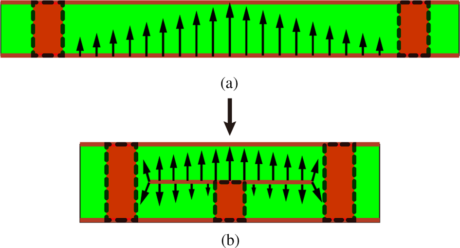
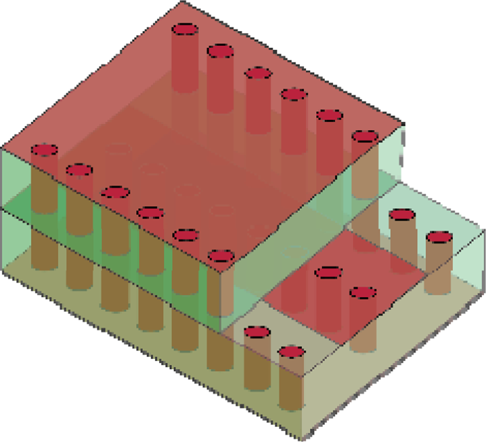
By meandering the electromagnetic field distribution within a closed structure, the folded substrate-integrated waveguide (FSIW) can also achieve size miniaturization. Figure 1 illustrates the cross-sectional geometries and fundamental mode E-field distributions of SIW and FSIW. The transverse dimension of FSIW is reduced by 50% compared to the full-mode SIW. Although FSIW research has been established and is widely used in microwave components [Reference Grigoropoulos, Sanz-Izquierdo and Young33–Reference Geng, Che and Deng35], to the authors' knowledge, there is no literature reporting on the study of LWAs based on FSIW. Therefore, the FSIW gives a new solution to realize a compact, highly integrated LWAs. In order to further elaborate the difference between FSIW and SIW, a three-dimensional structure schematic of T-type FSIW is given in Fig. 2. In the FSIW design development, the thickness of its dielectric layer does not affect the transmission performance; therefore, the dual dielectric layer structure does not affect the miniaturization in the vertical direction.
Cross-sectional geometries of SIW (a) and FSIW (b), and E-field distributions of the corresponding fundamental mode.

Three-dimensional structure schematic of T-type FSIW.

Based on T-type FSIW, a novel LWA with wide scanning angle and low cross-polarization is investigated in this paper. The slow-wave effect is introduced to the FSIW transmission line by etching transverse slots on the top surface of the FSIW. By regulating the length of the transverse slot periodically, the −1st order harmonics are excited and radiated, resulting in the formation of the LWA. The proposed LWA achieves a continuous scan from −42° backward to +68° forward, suppressing the open stopband (OSB) effect. The most outstanding work of this paper is the application of the FSIW to the design of the LWA. To the best of the authors' knowledge, this is the first study to propose the design of LWA based on FSIW, which provides novel ideas and solutions.
This paper is organized as follows. The configuration and analysis of the LWA are first presented in Section “Design and analysis of LWA,” followed by the experimental validation and discussion in Section “Experimental validation and discussion.” The conclusion is finally given in Section “Conclusion.”
Design and analysis of LWA
LWA configuration
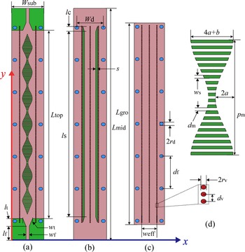
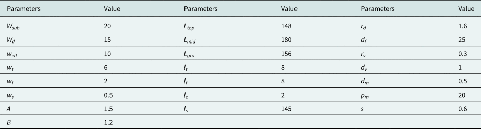
The geometrical structures of the proposed FSIW-based LWA are illustrated in Fig. 3. The main body of the LWA is based on a T-shaped FSIW, and the corresponding feed structure is of the gradient type. The T-shaped FSIW can be considered to fold down the outer quarter of the full-mode SIW and form a two-layer construction. The substrate used in the proposed LWA is Rogers 5880 (ɛr = 2.2 and tan δ = 0.0009). The thickness and the width of the single-layer structure are h = 0.508 mm and Ws = 20 mm, respectively. Periodically separated metalized vias with radius rv = 0.3 mm and spacing d 2 = 1 mm, connecting three metal layers to form equivalent electrical walls. The transverse slots with sinusoidal period changes are etched on the top metal layer, which can effectively accomplish the change of the mode from the propagating wave to the leaking wave. The length of the longest slot is 4a + b, and the length of the shortest slot is b. The spacing between adjacent slots remains constant at d 1. It needs to be noted that the perforations on the outside of the vias are mainly used for fixing the two dielectric layers and are not a factor in the antenna performance. It is replaced with hot pressing techniques to make the two layers of the structure fit together tightly in the engineering applications. All the dimensions mentioned in Fig. 3 are listed in Table 1. Full-wave simulator HFSS is used for optimizations of all the dimensions to achieve an enhanced beam scanning range with a low cross-polarization level.
Geometries of the proposed LWA. (a) Top layer. (b) Middle layer. (c) Ground layer. (d) Structure details.

Parameters of the proposed LWA (in mm)

Operation mechanism
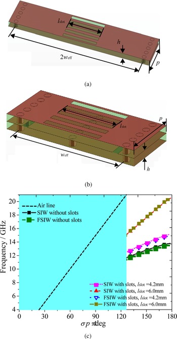
Foremost, the dispersion characteristics of the full-mode SIW and FSIW structures are analyzed. As shown in Figs 4(a) and 4(b), uniform slots etched on top of the SIW unit and T-type FSIW with period p = 5 mm. Except for the length of the slots, the other parameters mentioned in Fig. 4 are consistent with those in Table 1. Figure 4(c) illustrates the variation of the dispersion curve with the length of the slot. Figure 4(c) indicates that the dispersion characteristics of the FSIW are identical to those of the SIW with the same slotted structure, which also indicates that the FSIW still retains similar electromagnetic characteristics to the full-mode SIW despite the halving of the size. It can be seen that the lower cutoff frequencies of SIW and FSIW are about the same, and are not related to the length of the slots. Besides, the dispersion curves become flattered as the length of the slots increases, indicating that longer slots correspond to a more pronounced slow-wave feature.
Geometries of (a) SIW unit and (b) T-type FSIW unit, and the corresponding (c) dispersion curves with varied parameters (p = 5 mm).

Consistent slots change the phase constant in the FSIW corresponding to the conduction wave, but do not convert the slow-wave to a fast-wave and form radiation. To achieve the radiating wave, sinusoidal period modulation is introduced in this paper by excitation of the −1st order harmonic, which is a fast wave.
Without loss of generality, the pointing angle (θ) of the maximum beam of the LWA can be calculated from equation (1):

According to Floquet theory, the introduction of modulation excites an infinite space harmonics whose phase constant βn (n = 0, ±1, ±2 …) can be expressed as below:

where pm is the sinusoidal profile period and β 0 is the propagation phase constant of the fundamental mode. For the dispersion of the unit of FSIW in Fig. 4(c), it is assumed that it satisfies equation (3):

where g(ω) is the function of phase shift for the unit shown in Fig. 4(b).
Normally, the −1st space harmonic is excited and radiated with the periodic modulation. Therefore, the θ(ω) is expressed as

In the design of an LWA, the scanning beam at the broadside is very difficult to achieve because of the OSB. At the same time, the pointing angle (θ) = 0 and the phase constant β(ω) = 0. For the LWA proposed in this paper, the length of the slot slit is periodically varying, and the average length 2a + b is adopted to study the dispersion characteristics. Thus, according to equation (4) and the dimensions of the LWA shown in Fig. 3, the frequency corresponding to scanning at the broadside is achieved. Take lslot = 2a + b = 4.2 mm, p = 5 mm, and pm = 20 mm to obtain that when f = 10.1 GHz, the scanning beam of the antenna points to zero.
Experimental validation and discussion
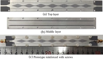
To validate the design, a prototype of the proposed antenna is fabricated and measured, as shown in Fig. 5. Figures 5(a) and 5(b) show the top and middle layers of the proposed LWA accordingly. Figure 5(c) shows the overall structure of the LWA, in which the two layers are tightly fitted together by two rows of screws. The N5230C vector network analyzer is used to measure the S-parameters, and the radiation patterns are measured in the anechoic chamber. It should be noted that both ports of the LWA are connected to signal ports in the S-parameter measurement, and one port of the antenna is connected to a 50-Ω matching load and the other port is connected to a signal source in the radiation pattern measurement.
Fabricated prototype of the proposed LWA. (a) Top layer. (b) Middle layer. (c) Prototype reinforced with screws.

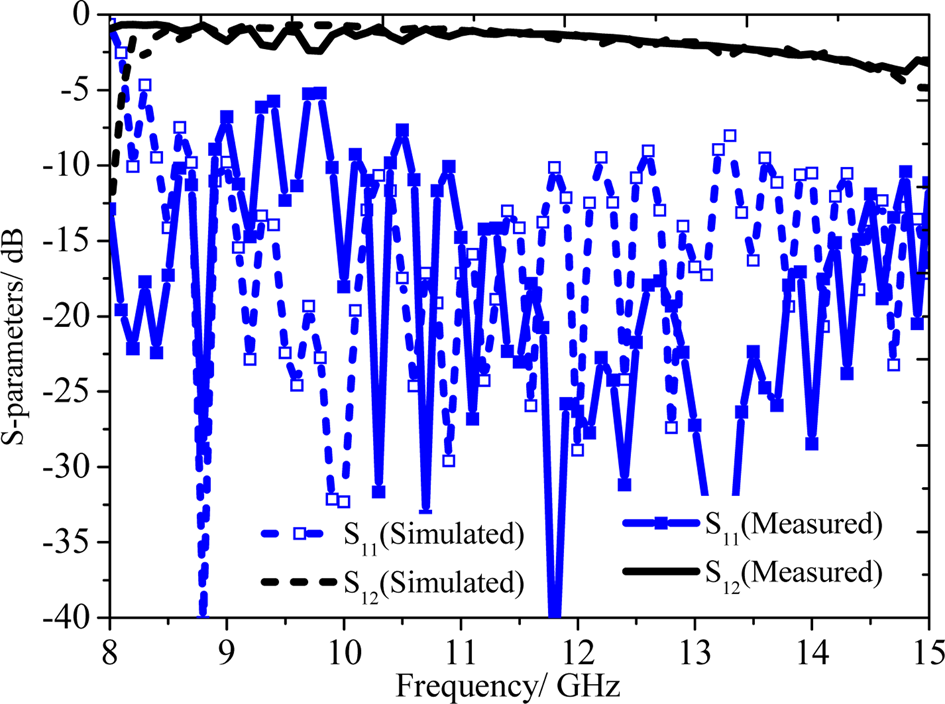
Figure 6 illustrates the comparison of S-parameters between measurements and simulations. There are discrepancies between the measured and simulated results of the S-parameters due to media loss, the measuring environment, and the mismatch between the fabricated prototype and the simulated model built in HFSS full-wave software. In the range from 8.3 to 11 GHz, the S 11 of the proposed LWA is greater than −10 dB, which indicates that the radiation efficiency is low.
Measured and simulated S-parameters of the proposed LWA.

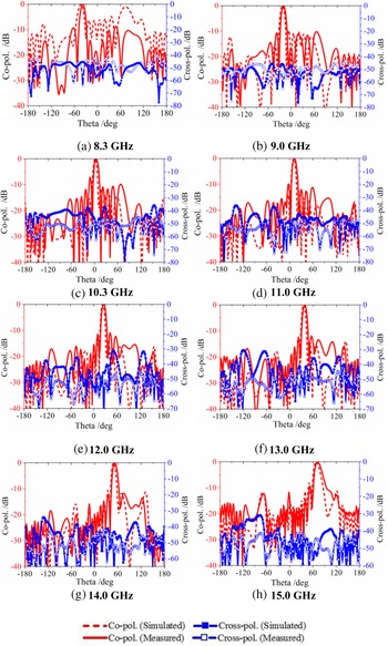
The measured and simulated normalized radiation patterns at 8.3, 9.0, 10.3, 11.0, 12.0, 13.0, 14.0, and 15.0 GHz are shown in Fig. 7, which illustrates beam direction with frequency on the yz-plane, as well as the features of co-polarization, cross-polarization, and side lobe. As the frequency increases, the LWA beam scans continuously from −42° backward to +68° forward, covering 110°. According to the radiation principle of LWA, the angle of beam scanning is closely related to the corresponding phase coefficient variation, and the magnitude of the phase coefficient depends on the modulation. Therefore, the length of the slot has a direct effect on the scanning range. As shown in Fig. 7(c), the antenna beam is radiated at the broadside direction and has a good performance, which indicates that the antenna mitigates the open-stopband well. Because of the homogeneous transverse slot, the LWA has good polarization isolation such that the values of cross-polarization are at a low level in the operating frequency range, and are less than −30 dB. As can be seen in Fig. 7, the radiation patterns at 8.3 and 15 GHz reveal a significant grating lobe. The reason for this phenomenon is that the phase coefficient and radiation coefficient of the LWA in the lower and higher frequency bands are dramatically undulating changes. According to the radiation principle of LWA, the radiation coefficient changes in the lower and higher frequency bands, which will cause the energy to be unevenly radiated along the transmission structure, thus forming a more significant grating lobe.
Measured and simulated far-field radiation patterns of the proposed LWA. (a) 8.3 GHz, (b) 9.0 GHz, (c) 10.3 GHz, (d) 11.0 GHz, (e) 12.0 GHz, (f) 13.0 GHz, (g) 14.0 GHz, and (h) 15.0 GHz.

According to equation (4), the momentum of the first space harmonic at 10.1 GHz is zero, which corresponds to the broadside radiation. In the simulated radiation patterns, the broadside radiation occurs at 10.3 GHz, respectively, which is in good agreement with the theoretical results.
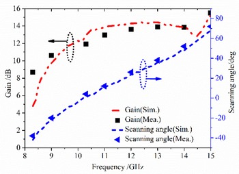
Figure 8 illustrates the realized gain and beam direction of the proposed LWA. A good agreement is observed between the results. Simulated and measured results show that the antenna achieves a wide scan range from backward end to forward. The constant gain is an important advantage of the proposed LWA over the conventional LWAs with dropping gain at the broadside radiation. At 15.0 GHz, the simulated model achieves a maximum realized gain of 15.1 dB.
Simulated and measured beam direction angles and gain of the proposed LWA.

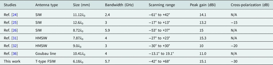
The proposed LWA based on T-type FSIW has good performance in scanning range, low cross-polarization, and radiation gain. To better demonstrate these characteristics, Table 2 compares the performances of the proposed LWA with other representative studies in the literature [Reference Liu, Gu, Zhu, Rong and Qian31–Reference Tang, Zhang, Hu, Zhuang, Kandwal, Zhang and Chen36]. In Table 2, λ 0 represents the wavelength in free space when the beams scan at broadside direction. The antenna proposed in this paper has a scanning range of backward −42° to forward +68°, covering 110° continuously. It is necessary to note that the cross-polarization characteristics have received little attention in the design of LWAs as shown in Table 2. The proposed LWA has a low cross-polarization mainly because of the geometric characteristics of the radiation structure. According to the radiation principle of waveguide structures, electromagnetic waves formed by purely transverse slot have a much lower cross-polarization. At the same time, the proposed LWA offers advantages in terms of radiation gain and structural size.
Comparative study of proposed LWA with other studies

Conclusion
A wide scanning angle LWA based on T-type FSIW has been proposed in this paper. A novel slow-wave transmission line based on FSIW was designed and analyzed. By etching sinusoidally modulated transverse slots on the top surface of FSIW, high harmonics are excited and radiated. The proposed LWA exhibits a wide scanning range, from −42° in the backward direction to +68° in the forward direction. Compared with other studies, the proposed LWA offers advantages in terms of cross-polarization, radiation gain, and structural size. The drawback of this solution is that it increases the complexity of LWA design. Designs that could have been done with just one layer of dielectric now need to be done on two layers.
Data
The data that support the findings of this study are available from the corresponding author upon a reasonable request.
 Shixiao Xiao was born in Fujian, China. He earned bachelor's and master's from Changsha University of Science and Technology, Changsha, China in 2003 and 2006, respectively. His research interests include mathematics applications and computer communication.
 Lianwu Yang was born in Hunan, China. He earned bachelor's and master's from Changsha University of Science and Technology, Changsha, China, in 2003 and 2006, respectively. His research interests include mathematics applications and computer communication.