1 Introduction
Moving contact lines are common in nature and our daily life, e.g. the motion of rain drops on window glass, coffee rings left by evaporation of coffee drops, wetting on lotus leaves, etc. The moving contact line (MCL) problem also has many applications in industrial processes, like painting, coating and oil recovery, etc. Therefore, the problem has been studied extensively; see recent review papers by Pismen (Reference Pismen2002), Blake (Reference Blake2006), Bonn et al. (Reference Bonn, Eggers, Indekeu, Meunier and Rolley2009), Snoeijer & Andreotti (Reference Snoeijer and Andreotti2013) and the references therein.
Moving contact line is a challenging problem in fluid dynamics. The standard two-phase Navier–Stokes equations with a no-slip boundary condition will lead to a non-physical, non-integrable stress (Huh Reference Huh and Scriven1971; Dussan Reference Dussan1979). This is the so-called contact line paradox. There are many efforts to solve this paradox. A natural way is to relax the no-slip boundary condition. Instead, one could use the Navier slip boundary condition (Huh Reference Huh and Scriven1971; Cox Reference Cox1986; Zhou & Sheng Reference Zhou and Sheng1990; Haley & Miksis Reference Haley and Miksis1991; Spelt Reference Spelt2005; Ren & E Reference Ren and E2007). In some applications, an effective slip condition can be induced by numerical methods (Renardy, Renardy & Li Reference Renardy, Renardy and Li2001; Marmottant & Villermaux Reference Marmottant and Villermaux2004). The other approaches to cure the paradox include: assuming a precursor thin film and a disjoint pressure (Schwartz & Eley Reference Schwartz and Eley1998; Pismen & Pomeau Reference Pismen and Pomeau2000; Eggers Reference Eggers2005); deriving a new thermodynamics for surfaces (Shikhmurzaev Reference Shikhmurzaev1993); treating the moving contact line as a thermally activated process (Blake Reference Blake2006; Seveno et al. Reference Seveno, Vaillant, Rioboo, Adao, Conti and De Coninck2009; Blake & De Coninck Reference Blake and De Coninck2011), using a diffuse-interface model for moving contact lines (Gurtin, Polignone & Vinals Reference Gurtin, Polignone and Vinals1996; Seppecher Reference Seppecher1996; Jacqmin Reference Jacqmin2000; Qian, Wang & Sheng Reference Qian, Wang and Sheng2003; Yue & Feng Reference Yue and Feng2011a ), etc.
The diffuse-interface approach for moving contact lines has become popular in recent years (Anderson, McFadden & Wheeler Reference Anderson, McFadden and Wheeler1998; Qian, Wang & Sheng Reference Qian, Wang and Sheng2004; Ding & Spelt Reference Ding and Spelt2007; Carlson, Do-Quang & Amberg Reference Carlson, Do-Quang and Amberg2009; Ren & E Reference Ren and E2011; Sibley et al. Reference Sibley, Nold, Savva and Kalliadasis2013b ; Sui, Ding & Spelt Reference Sui, Ding and Spelt2014; Shen, Yang & Yu Reference Shen, Yang and Yu2015; Fakhari & Bolster Reference Fakhari and Bolster2017). In this approach, the interface is a thin diffuse layer between different fluids represented by a phase-field function. Intermolecular diffusion, caused by the non-equilibrium of the chemical potential, occurs in the thin layer. The chemical diffusion can cause the motion of the contact line, even without using a slip boundary condition on the solid boundary (Chen, Jasnow & Viñals Reference Chen, Jasnow and Viñals2000; Jacqmin Reference Jacqmin2000; Briant, Wagner & Yeomans Reference Briant, Wagner and Yeomans2004; Yue & Feng Reference Yue and Feng2011b ; Sibley et al. Reference Sibley, Nold, Savva and Kalliadasis2013c ). On the other hand, it is possible to combine the diffuse-interface model with a slip boundary condition. Qian et al. (Reference Qian, Wang and Sheng2003) proposed a phase-field model with a generalized Navier slip boundary condition (GNBC). The model takes account of the effect of the uncompensated Young’s stress, which is important to understand the difference between the dynamic contact angle and the Young’s angle on a molecular scale (Qian et al. Reference Qian, Wang and Sheng2003; Ren & E Reference Ren and E2007). Theoretically, the model can be derived from the Onsager variational principle (Qian, Wang & Sheng Reference Qian, Wang and Sheng2006). Numerical simulations using this model fit remarkably well with the molecular dynamics simulations (Qian et al. Reference Qian, Wang and Sheng2003) and physical experiments (Guo et al. Reference Guo, Gao, Xiong, Wang, Wang, Sheng and Tong2013). The model has also been used in problems with chemically patterned boundaries (Wang, Qian & Sheng Reference Wang, Qian and Sheng2008), dynamic wetting problems (Carlson et al. Reference Carlson, Do-Quang and Amberg2009; Yamamoto et al. Reference Yamamoto, Tokieda, Wakimoto, Ito and Katoh2014), etc. Several numerical methods for the model have been developed (Bao et al. Reference Bao, Shi, Sun and Wang2012; Gao & Wang Reference Gao and Wang2012, Reference Gao and Wang2014; Shen et al. Reference Shen, Yang and Yu2015; Aland & Chen Reference Aland and Chen2016).
Phase-field models are convenient for numerical calculations (Yue et al. Reference Yue, Feng, Liu and Shen2004; Teigen et al. Reference Teigen, Song, Lowengrub and Voigt2011; Sui et al. Reference Sui, Ding and Spelt2014). One does not need to track the interface explicitly as in using a sharp-interface model. The phase-field function, which is usually described by a Cahn–Hilliard (Cahn & Hilliard Reference Cahn and Hilliard1958) equation or an Allen–Cahn equation (Allen & Cahn Reference Allen and Cahn1979), can capture the interface implicitly and automatically. This makes computations and analysis for the phase-field model much easier than other approaches. However, there are also some restrictions to using a diffuse-interface model in real simulations. A key issue is that the thickness of the diffuse interface cannot be chosen as small as the physical size (Khatavkar, Anderson & Meijer Reference Khatavkar, Anderson and Meijer2006), due to the restriction of the computational resources. One often chooses a much larger (than physical values) interface thickness parameter (or a dimensionless Cahn number) in simulations. However, only when a phase-field model approximates a sharp-interface limit correctly can the numerical simulations by this model with relatively large Cahn number be trusted and comparable to experiments. Therefore, it is very important to study the sharp-interface limit of a phase-field model (Caginalp & Chen Reference Caginalp and Chen1998; Chen, Wang & Xu Reference Chen, Wang and Xu2014).
The sharp-interface limits of diffuse-interface models for two-phase flow without moving contact lines have been studied extensively, both theoretically and numerically (Lowengrub & Truskinovsky Reference Lowengrub and Truskinovsky1998; Jacqmin Reference Jacqmin1999; Khatavkar et al.
Reference Khatavkar, Anderson and Meijer2006; Huang, Shu & Chew Reference Huang, Shu and Chew2009; Magaletti et al.
Reference Magaletti, Picano, Chinappi, Marino and Casciola2013; Sibley, Nold & Kalliadasis Reference Sibley, Nold and Kalliadasis2013a
). In comparison, there are far fewer studies for the sharp-interface limits of the phase-field models for moving contact lines (Yue, Zhou & Feng Reference Yue, Zhou and Feng2010; Kusumaatmaja, Hemingway & Fielding Reference Kusumaatmaja, Hemingway and Fielding2016). Important progress has been made by Yue et al. (Reference Yue, Zhou and Feng2010). They studied the sharp-interface limit of a phase-field model with a no-slip boundary condition and found a surprising result that only when the mobility parameter (denoted
 $\mathsf{L}_{\mathsf{d}}$
) is of order
 $O(1)$
does the phase-field model have a sharp-interface limit as the Cahn number (denoted as
 $\unicode[STIX]{x1D700}$
) goes to zero. Notice that the usual choice of the mobility parameter is of order
 $O(\unicode[STIX]{x1D700}^{a})$
,
 $1\leqslant a\leqslant 3$
for problems without moving contact lines (Magaletti et al.
Reference Magaletti, Picano, Chinappi, Marino and Casciola2013). For the phase-field model with the generalized Navier slip boundary condition, the only study of its sharp-interface limit is by Wang & Wang (Reference Wang and Wang2007). They also assumed the mobility parameter is of order
 $O(1)$
. Their asymptotic analysis shows that the sharp-interface limit of the model is a Hele-Shaw flow coupled with a standard Navier slip boundary condition. So far, the sharp-interface limit of a phase-field model for a moving contact line problem under the standard choice for the mobility parameter, e.g.
 $\mathsf{L}_{\mathsf{d}}=O(\unicode[STIX]{x1D700})$
or
 $\mathsf{L}_{\mathsf{d}}=O(\unicode[STIX]{x1D700}^{2})$
, is unclear. This is the motivation of our study.
We study the sharp-interface limit of the phase-field model for binary fluids with the GNBC by asymptotic analysis and numerical simulations. In asymptotic analysis, we assume that the mobility number
 $\mathsf{L}_{\mathsf{d}}$
is of order
 $O(\unicode[STIX]{x1D700}^{a}),a=1,2$
and consider several typical scalings of phenomenological boundary relaxation parameter
 $\mathsf{V}_{\mathsf{s}}$
in the GNBC model. We show that the sharp-interface limit of the bulk equation is a standard two-phase Navier–Stokes equation in both cases of
 $\mathsf{L}_{\mathsf{d}}=O(\unicode[STIX]{x1D700})$
and
 $\mathsf{L}_{\mathsf{d}}=O(\unicode[STIX]{x1D700}^{2})$
. However, the sharp-interface limits of the boundary condition are affected by both
 $\mathsf{L}_{\mathsf{d}}$
and
 $\mathsf{V}_{\mathsf{s}}$
. We first consider the case
 $\mathsf{L}_{\mathsf{d}}=O(\unicode[STIX]{x1D700})$
. When
 $\mathsf{V}_{\mathsf{s}}=O(\unicode[STIX]{x1D700}^{b})$
with
 $b=0,-1$
, we obtain a sharp-interface version of the GNBC with different contact line velocities. When
 $\mathsf{V}_{\mathsf{s}}=O(1)$
, the velocity of the contact line is equal to the fluid velocity, while when
 $\mathsf{V}_{\mathsf{s}}=O(\unicode[STIX]{x1D700}^{-1})$
, the velocity of the contact line is different from the fluid velocity due to the contribution of the chemical diffusion on the boundary. When
 $\mathsf{V}_{\mathsf{s}}=O(\unicode[STIX]{x1D700}^{-2})$
, we obtain the standard Navier slip boundary condition together with the condition that the dynamic contact angle is equal to the static contact angle. We then study the case
 $\mathsf{L}_{\mathsf{d}}=O(\unicode[STIX]{x1D700}^{2})$
. It is found that when
 $\mathsf{V}_{\mathsf{s}}=O(1)$
and
 $\mathsf{V}_{\mathsf{s}}=O(\unicode[STIX]{x1D700}^{-2})$
, we obtain the same result as that for the
 $\mathsf{L}_{\mathsf{d}}=O(\unicode[STIX]{x1D700})$
case. However, when
 $\mathsf{V}_{\mathsf{s}}=O(\unicode[STIX]{x1D700}^{-1})$
, we get boundary conditions that are similar to the
 $\mathsf{L}_{\mathsf{d}}=O(\unicode[STIX]{x1D700})$
case, but not in a closed form, due to the hydrodynamic coupling with balanced bulk phase diffusion and boundary phase relaxation. Numerical experiments for a Couette flow show the different sharp-interface limits for various choices of
 $\mathsf{L}_{\mathsf{d}}$
and
 $\mathsf{V}_{\mathsf{s}}$
. Furthermore, numerical results also reveal the different convergence rates for different choices of the two parameters. For very large relaxation parameter
 $\mathsf{V}_{\mathsf{s}}=O(\unicode[STIX]{x1D700}^{-3})$
, the numerical results are very similar to the results by Yue et al. (Reference Yue, Zhou and Feng2010). Note that, for simplicity, in this paper we only consider the moving contact line problem for binary fluids, e.g. an oil–water mixture, where the density and viscosity of the two fluids are matched or have small differences such that the Boussinesq approximation can be applied.
The structure of the paper is as follows. In § 2, we introduce the phase-field model with the GNBC and its non-dimensionalization. In § 3, the sharp-interface limits of the phase-field model with the GNBC are obtained for various choices of
 $\mathsf{L}_{\mathsf{d}}$
and
 $\mathsf{V}_{\mathsf{s}}$
by asymptotic analysis. In § 4, we show the numerical experiments for a Couette flow using a recently developed second order scheme. Finally, some concluding remarks are given in § 5.
2 The phase-field model with generalized Navier slip boundary condition
A Cahn–Hilliard–Navier–Stokes (CHNS) system with the generalized Navier boundary condition (GNBC) is proposed by Qian et al. (Reference Qian, Wang and Sheng2003) to describe a two-phase flow with moving contact lines. The CHNS system reads
 $$\begin{eqnarray}\left.\begin{array}{@{}c@{}}{\displaystyle \frac{\unicode[STIX]{x2202}\unicode[STIX]{x1D719}}{\unicode[STIX]{x2202}t}}+\boldsymbol{v}\boldsymbol{\cdot }\unicode[STIX]{x1D735}\unicode[STIX]{x1D719}=M\unicode[STIX]{x0394}\unicode[STIX]{x1D707},\quad \unicode[STIX]{x1D707}=-K\unicode[STIX]{x0394}\unicode[STIX]{x1D719}-r(\unicode[STIX]{x1D719}-\unicode[STIX]{x1D719}^{3}),\\ \unicode[STIX]{x1D70C}\left[{\displaystyle \frac{\unicode[STIX]{x2202}\boldsymbol{v}}{\unicode[STIX]{x2202}t}}+(\boldsymbol{v}\boldsymbol{\cdot }\unicode[STIX]{x1D735})\boldsymbol{v}\right]=\boldsymbol{F}-\unicode[STIX]{x1D735}p+\unicode[STIX]{x1D702}\unicode[STIX]{x0394}\boldsymbol{v}+\unicode[STIX]{x1D707}\unicode[STIX]{x1D735}\unicode[STIX]{x1D719},\quad \unicode[STIX]{x1D735}\boldsymbol{\cdot }\boldsymbol{v}=0.\end{array}\right\}\end{eqnarray}$$
The first equation is the Cahn–Hilliard equation. Here
 $\unicode[STIX]{x1D719}$
is the phase-field function, and
 $\unicode[STIX]{x1D707}$
is the chemical potential. The thickness of the diffuse interface is
 $\unicode[STIX]{x1D716}=\sqrt{K/r}$
and the fluid–fluid interface tension is given by
 $\unicode[STIX]{x1D6FE}=2\sqrt{2}r\unicode[STIX]{x1D716}/3$
.
 $M$
is a phenomenological mobility coefficient. The second equation in (2.1) is the incompressible Navier–Stokes equation for two-phase flow. Here
 $\unicode[STIX]{x1D707}\unicode[STIX]{x1D735}\unicode[STIX]{x1D719}$
describes the capillary force exerted on the fluids by the interface. For simplicity, we assume that the two fluids have equal density
 $\unicode[STIX]{x1D70C}$
and viscosity
 $\unicode[STIX]{x1D702}$
.
The GNBC on the solid boundary, proposed by Qian et al. (Reference Qian, Wang and Sheng2003, Reference Qian, Wang and Sheng2006), is
 $$\begin{eqnarray}\unicode[STIX]{x1D6FD}(v_{\unicode[STIX]{x1D70F}}-v_{w})=-\unicode[STIX]{x1D702}\unicode[STIX]{x2202}_{n}v_{\unicode[STIX]{x1D70F}}+L(\unicode[STIX]{x1D719})\unicode[STIX]{x2202}_{\unicode[STIX]{x1D70F}}\unicode[STIX]{x1D719},\quad v_{n}=0,\end{eqnarray}$$
 $$\begin{eqnarray}L(\unicode[STIX]{x1D719})=K\unicode[STIX]{x2202}_{n}\unicode[STIX]{x1D719}+{\displaystyle \frac{\unicode[STIX]{x2202}\unicode[STIX]{x1D6FE}_{wf}(\unicode[STIX]{x1D719})}{\unicode[STIX]{x2202}\unicode[STIX]{x1D719}}},\quad \unicode[STIX]{x1D6FE}_{wf}(\unicode[STIX]{x1D719})={\displaystyle \frac{\unicode[STIX]{x1D6FE}}{4}}\cos \unicode[STIX]{x1D703}_{s}(3\unicode[STIX]{x1D719}-\unicode[STIX]{x1D719}^{3}).\end{eqnarray}$$
Here
 $v_{n}$
and
 $v_{\unicode[STIX]{x1D70F}}$
are respectively the normal fluid velocity and the tangential fluid velocity on the solid boundary;
 $v_{w}$
is the velocity of the boundary itself. We assume the wall only moves in a tangential direction.
 $\unicode[STIX]{x1D6FD}$
is a slip coefficient and the slip length is given as
 $l_{s}=\unicode[STIX]{x1D702}/\unicode[STIX]{x1D6FD}$
.
 $\unicode[STIX]{x1D6FE}_{wf}(\unicode[STIX]{x1D719})$
is the solid–fluid interfacial energy density (up to a constant) and
 $\unicode[STIX]{x1D703}_{s}$
is the static contact angle of the phase
 $\unicode[STIX]{x1D719}=-1$
.
 $L(\unicode[STIX]{x1D719})\unicode[STIX]{x2202}_{\unicode[STIX]{x1D70F}}\unicode[STIX]{x1D719}$
represents the uncompensated Young stress.
In addition, the boundary conditions for the phase-field function
 $\unicode[STIX]{x1D719}$
and the chemical potential
 $\unicode[STIX]{x1D707}$
are given by (see Jacqmin Reference Jacqmin2000, Yue & Feng Reference Yue and Feng2011b
, Qian et al.
Reference Qian, Wang and Sheng2003)
 $$\begin{eqnarray}\left.\begin{array}{@{}c@{}}{\displaystyle \frac{\unicode[STIX]{x2202}\unicode[STIX]{x1D719}}{\unicode[STIX]{x2202}t}}+v_{\unicode[STIX]{x1D70F}}\unicode[STIX]{x2202}_{\unicode[STIX]{x1D70F}}\unicode[STIX]{x1D719}=-\unicode[STIX]{x1D6E4}L(\unicode[STIX]{x1D719}),\\ \unicode[STIX]{x2202}_{n}\unicode[STIX]{x1D707}=0,\end{array}\right\}\end{eqnarray}$$
with
 $\unicode[STIX]{x1D6E4}$
being a positive phenomenological relaxation parameter.
To study the behaviour of the CHNS system with the GNBC condition, it is useful to non-dimensionalize the system. Suppose the typical length scale in the two-phase flow system is given by
 $l$
and the characteristic velocity is
 $v^{\ast }$
. We then scale the velocity by
 $v^{\ast }$
, the length by
 $l$
, the time by
 $l/v^{\ast }$
, the body force(density)
 $\boldsymbol{F}$
by
 $\unicode[STIX]{x1D702}v^{\ast }/l^{2}$
and the pressure by
 $\unicode[STIX]{x1D702}v^{\ast }/l$
. With six dimensionless parameters
 $$\begin{eqnarray}\displaystyle \left.\begin{array}{@{}c@{}}\mathsf{L}_{\mathsf{d}}={\displaystyle \frac{3M\unicode[STIX]{x1D6FE}}{2\sqrt{2}v^{\ast }l^{2}}}\text{ (the mobility number)},\quad Re={\displaystyle \frac{\unicode[STIX]{x1D70C}v^{\ast }l}{\unicode[STIX]{x1D702}}}~\text{(the Reynolds number)},\\ \mathsf{B}={\displaystyle \frac{3\unicode[STIX]{x1D6FE}}{2\sqrt{2}\unicode[STIX]{x1D702}v^{\ast }}}\text{(inverse of the Capillary number)},\\ \mathsf{V}_{\mathsf{s}}={\displaystyle \frac{3\unicode[STIX]{x1D6FE}\unicode[STIX]{x1D6E4}l}{2\sqrt{2}v^{\ast }}}\text{(a relaxation parameter)},\\ \mathsf{l}_{\mathsf{s}}={\displaystyle \frac{l_{s}}{l}}\text{ (the dimensionless slip length)},\quad \unicode[STIX]{x1D700}={\displaystyle \frac{\unicode[STIX]{x1D716}}{l}}\text{ (the Cahn number)},\end{array}\right\}\quad & & \displaystyle\end{eqnarray}$$
we have the following dimensionless Cahn–Hilliard-Navier–Stokes system:
 $$\begin{eqnarray}\left.\begin{array}{@{}c@{}}{\displaystyle \frac{\unicode[STIX]{x2202}\unicode[STIX]{x1D719}}{\unicode[STIX]{x2202}t}}+\boldsymbol{v}\boldsymbol{\cdot }\unicode[STIX]{x1D735}\unicode[STIX]{x1D719}=\mathsf{L}_{\mathsf{d}}\unicode[STIX]{x0394}\unicode[STIX]{x1D707},\quad \unicode[STIX]{x1D707}=-\unicode[STIX]{x1D700}\unicode[STIX]{x0394}\unicode[STIX]{x1D719}-\unicode[STIX]{x1D719}/\unicode[STIX]{x1D700}+\unicode[STIX]{x1D719}^{3}/\unicode[STIX]{x1D700},\\ Re\left[{\displaystyle \frac{\unicode[STIX]{x2202}\boldsymbol{v}}{\unicode[STIX]{x2202}t}}+(\boldsymbol{v}\boldsymbol{\cdot }\unicode[STIX]{x1D735})\boldsymbol{v}\right]=\boldsymbol{F}-\unicode[STIX]{x1D735}p+\unicode[STIX]{x0394}\boldsymbol{v}+\mathsf{B}\unicode[STIX]{x1D707}\unicode[STIX]{x1D735}\unicode[STIX]{x1D719},\\ \unicode[STIX]{x1D735}\boldsymbol{\cdot }\boldsymbol{ v}=0,\end{array}\right\}\end{eqnarray}$$
with the boundary conditions
 $$\begin{eqnarray}\left.\begin{array}{@{}c@{}}{\displaystyle \frac{\unicode[STIX]{x2202}\unicode[STIX]{x1D719}}{\unicode[STIX]{x2202}t}}+v_{\unicode[STIX]{x1D70F}}\unicode[STIX]{x2202}_{\unicode[STIX]{x1D70F}}\unicode[STIX]{x1D719}=-\mathsf{V}_{\mathsf{s}}{\mathcal{L}}(\unicode[STIX]{x1D719}),\\ \mathsf{l}_{\mathsf{s}}^{-1}(v_{\unicode[STIX]{x1D70F}}-v_{w})=-\unicode[STIX]{x2202}_{n}v_{\unicode[STIX]{x1D70F}}+\mathsf{B}{\mathcal{L}}(\unicode[STIX]{x1D719})\unicode[STIX]{x2202}_{\unicode[STIX]{x1D70F}}\unicode[STIX]{x1D719},\\ \unicode[STIX]{x2202}_{n}\unicode[STIX]{x1D707}=0,\quad v_{n}=0,\end{array}\right\}\end{eqnarray}$$
where
 ${\mathcal{L}}(\unicode[STIX]{x1D719})=\unicode[STIX]{x1D700}\unicode[STIX]{x2202}_{n}\unicode[STIX]{x1D719}+\unicode[STIX]{x2202}\unicode[STIX]{x1D6FE}_{wf}(\unicode[STIX]{x1D719})/\unicode[STIX]{x2202}\unicode[STIX]{x1D719}$
and
 $\unicode[STIX]{x1D6FE}_{wf}(\unicode[STIX]{x1D719})=\sqrt{2}/6\cos \unicode[STIX]{x1D703}_{s}(3\unicode[STIX]{x1D719}-\unicode[STIX]{x1D719}^{3})$
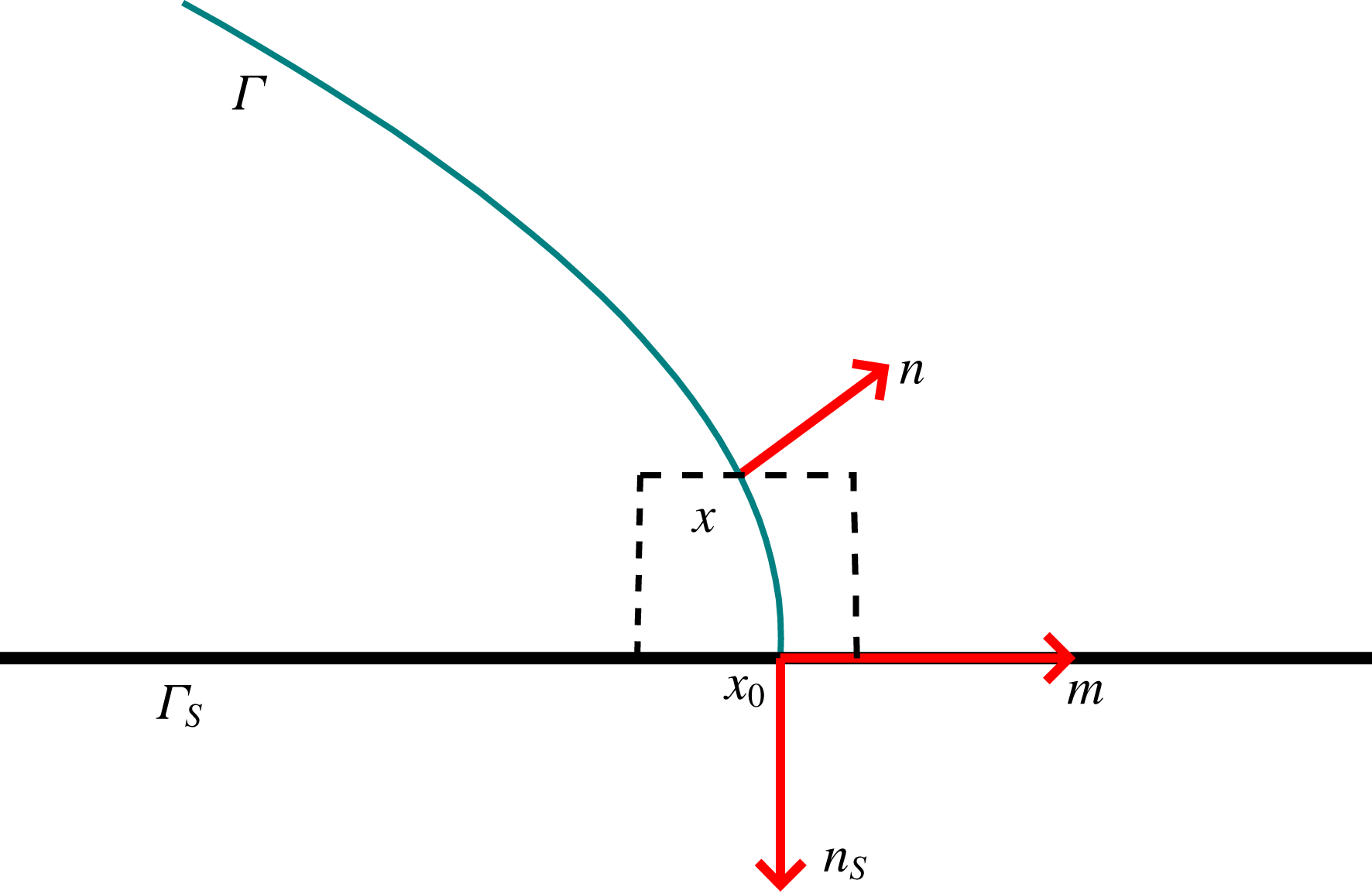
. We now clarify some notations in the boundary condition. Suppose the unit outward normal vector on the solid boundary is given by
 $\boldsymbol{n}_{S}$
(see figure 1). Then we have
 $v_{n}=\boldsymbol{v}\boldsymbol{\cdot }\boldsymbol{n}_{S}$
,
 $v_{\unicode[STIX]{x1D70F}}=\boldsymbol{v}-v_{n}\boldsymbol{n}_{S}$
,
 $\unicode[STIX]{x2202}_{n}=\boldsymbol{n}_{S}\boldsymbol{\cdot }\unicode[STIX]{x1D735}$
and
 $\unicode[STIX]{x2202}_{\unicode[STIX]{x1D70F}}=\unicode[STIX]{x1D735}-\boldsymbol{n}_{S}(\boldsymbol{n}_{S}\boldsymbol{\cdot }\unicode[STIX]{x1D735})$
.
A liquid drop on a planar solid surface
 $\unicode[STIX]{x1D6E4}_{S}$
with a contact line
 $L$
.

3 The asymptotic analysis
We do asymptotic analysis for the CHNS system (2.6)–(2.7). Here we assume the mobility number satisfies
 $\mathsf{L}_{\mathsf{d}}=O(\unicode[STIX]{x1D700}^{a})$
, with
 $a=1,2$
. In §§ 3.1 and 3.2, we give a detailed analysis for the case
 $\mathsf{L}_{\mathsf{d}}=O(\unicode[STIX]{x1D700})$
. We show that such a choice of mobility will lead to the standard two-phase Navier–Stokes equation inside the domain. Furthermore, this assumption also makes it possible to derive proper boundary conditions for the sharp-interface limit of the diffuse-interface model. We show that different set-ups of the relaxation parameter
 $\mathsf{V}_{\mathsf{s}}=O(\unicode[STIX]{x1D700}^{b})$
,
 $b=0,-1,-2$
will lead to different boundary conditions. In § 3.3, we discuss the case that the mobility number
 $\mathsf{L}_{\mathsf{d}}=O(\unicode[STIX]{x1D700}^{2})$
, which is more physically favourable, as shown in Magaletti et al. (Reference Magaletti, Picano, Chinappi, Marino and Casciola2013).
To make the presentation in this section clear, we use
 $\unicode[STIX]{x1D719}_{\unicode[STIX]{x1D700}}$
,
 $\boldsymbol{v}_{\unicode[STIX]{x1D700}}$
and
 $p_{\unicode[STIX]{x1D700}}$
instead of
 $\unicode[STIX]{x1D719}$
,
 $\boldsymbol{v}$
and
 $p$
in the system (2.6)–(2.7), to show explicitly that these functions depend on
 $\unicode[STIX]{x1D700}$
. We suppose that the system is located in a domain
 $\unicode[STIX]{x1D6FA}$
with solid boundary
 $\unicode[STIX]{x1D6E4}_{S}\subseteq \unicode[STIX]{x2202}\unicode[STIX]{x1D6FA}$
(as shown in figure 1). Suppose that the two-phase interface is given by the zero level set of the phase-field function
 $\unicode[STIX]{x1D719}_{\unicode[STIX]{x1D700}}$
,
 $$\begin{eqnarray}\unicode[STIX]{x1D6E4}:=\{x\in \unicode[STIX]{x1D6FA}\mid \unicode[STIX]{x1D719}_{\unicode[STIX]{x1D700}}(x)=0\}.\end{eqnarray}$$
We let
 $\unicode[STIX]{x1D6FA}^{-}=\{x\in \unicode[STIX]{x1D6FA}\,|\,\unicode[STIX]{x1D719}_{\unicode[STIX]{x1D700}}<0\}$
denote the domain occupied by fluid 1 and
 $\unicode[STIX]{x1D6FA}^{+}=\{x\in \unicode[STIX]{x1D6FA}\,|\,\unicode[STIX]{x1D719}_{\unicode[STIX]{x1D700}}>0\}$
the domain occupied by fluid 2. The methodology and notations are similar to those in Pego (Reference Pego1989) for phase-field equations, in Lowengrub & Truskinovsky (Reference Lowengrub and Truskinovsky1998) for two-phase flows without a moving contact line and in Wang & Wang (Reference Wang and Wang2007) for moving contact line problems with
 $\mathsf{L}_{\mathsf{d}}=O(1)$
.
3.1 The bulk equations for
 $\mathsf{L}_{\mathsf{d}}=O(\unicode[STIX]{x1D700})$

We first do asymptotic analysis for the CHNS system far from the boundary. The analysis is the same as that for two-phase flow without contact lines. We will state the key steps of the analysis and illustrate the main results. In the next subsection, the bulk analysis here will be combined with the analysis near the boundary to derive the sharp-interface limits of the GNBC.
Let
 $\mathsf{L}_{\mathsf{d}}=\unicode[STIX]{x1D700}l_{d}$
, where
 $l_{d}$
is a proportional constant independent of
 $\unicode[STIX]{x1D700}$
. Consider the CHNS system far from the boundary of
 $\unicode[STIX]{x1D6FA}$
. We first do outer expansions far from the interface
 $\unicode[STIX]{x1D6E4}$
, then we consider inner expansions near
 $\unicode[STIX]{x1D6E4}$
. Combining them together, we will obtain the sharp-interface limit of the CHNS system in
 $\unicode[STIX]{x1D6FA}$
.
Outer expansions. Far from the two-phase interface
 $\unicode[STIX]{x1D6E4}$
, we use the following ansatz:
 $$\begin{eqnarray}\left.\begin{array}{@{}c@{}}\boldsymbol{v}_{\unicode[STIX]{x1D700}}^{\pm }=\boldsymbol{v}_{0}^{\pm }+\unicode[STIX]{x1D700}\boldsymbol{v}_{1}^{\pm }+\unicode[STIX]{x1D700}^{2}\boldsymbol{v}_{2}^{\pm }+\cdots \,,\\ \unicode[STIX]{x1D719}_{\unicode[STIX]{x1D700}}^{\pm }=\unicode[STIX]{x1D719}_{0}^{\pm }+\unicode[STIX]{x1D700}\unicode[STIX]{x1D719}_{1}^{\pm }+\unicode[STIX]{x1D700}^{2}\unicode[STIX]{x1D719}_{2}^{\pm }+\cdots \,,\\ p_{\unicode[STIX]{x1D700}}^{\pm }=p_{0}^{\pm }+\unicode[STIX]{x1D700}p_{1}^{\pm }+\unicode[STIX]{x1D700}^{2}p_{2}^{\pm }+\cdots \,.\end{array}\right\}\end{eqnarray}$$
Here
 $f^{\pm }$
denotes the restriction of a function
 $f$
in
 $\unicode[STIX]{x1D6FA}^{+}$
and
 $\unicode[STIX]{x1D6FA}^{-}$
respectively. For
 $\unicode[STIX]{x1D707}_{\unicode[STIX]{x1D700}}$
, we easily have
 $$\begin{eqnarray}\unicode[STIX]{x1D707}_{\unicode[STIX]{x1D700}}^{\pm }=\unicode[STIX]{x1D700}^{-1}\unicode[STIX]{x1D707}_{0}^{\pm }+\unicode[STIX]{x1D707}_{1}^{\pm }+\unicode[STIX]{x1D700}\unicode[STIX]{x1D707}_{2}^{\pm }+\cdots \,,\end{eqnarray}$$
where
 $$\begin{eqnarray}\unicode[STIX]{x1D707}_{0}^{\pm }=-\unicode[STIX]{x1D719}_{0}^{\pm }+(\unicode[STIX]{x1D719}_{0}^{\pm })^{3}.\end{eqnarray}$$
We substitute the above expansions in the CHNS system (2.6). The leading order of the first equation of (2.6) gives
 $$\begin{eqnarray}{\displaystyle \frac{\unicode[STIX]{x2202}\unicode[STIX]{x1D719}_{0}^{\pm }}{\unicode[STIX]{x2202}t}}+\boldsymbol{v}_{0}\boldsymbol{\cdot }\unicode[STIX]{x1D735}\unicode[STIX]{x1D719}_{0}^{\pm }=l_{d}\unicode[STIX]{x0394}\unicode[STIX]{x1D707}_{0}^{\pm }.\end{eqnarray}$$
The leading order of the second equation of (2.6) gives
 $$\begin{eqnarray}\unicode[STIX]{x1D707}_{0}^{\pm }\unicode[STIX]{x1D735}\unicode[STIX]{x1D719}_{0}^{\pm }=0.\end{eqnarray}$$
More precisely, we have
 $$\begin{eqnarray}(-\unicode[STIX]{x1D719}_{0}^{\pm }+(\unicode[STIX]{x1D719}_{0}^{\pm })^{3})\unicode[STIX]{x1D735}\unicode[STIX]{x1D719}_{0}^{\pm }=\unicode[STIX]{x1D735}\left({\displaystyle \frac{(1-(\unicode[STIX]{x1D719}_{0}^{\pm })^{2})^{2}}{4}}\right)=0.\end{eqnarray}$$
This implies that
 $$\begin{eqnarray}\unicode[STIX]{x1D719}_{0}^{\pm }=c_{\pm }\quad \text{in }\unicode[STIX]{x1D6FA}^{\pm },\end{eqnarray}$$
where
 $c_{\pm }$
are two constants such that
 $c_{+}>0$
and
 $c_{-}<0$
. For the third equation of (2.6), at the leading order, we have
 $$\begin{eqnarray}\unicode[STIX]{x1D735}\boldsymbol{\cdot }\boldsymbol{v}_{0}^{\pm }=0.\end{eqnarray}$$
By direct calculations, we also have the next order of the second equation of (2.6) as
 $$\begin{eqnarray}Re\left[{\displaystyle \frac{\unicode[STIX]{x2202}\boldsymbol{v}_{0}^{\pm }}{\unicode[STIX]{x2202}t}}+(\boldsymbol{v}_{0}^{\pm }\boldsymbol{\cdot }\unicode[STIX]{x1D735})\boldsymbol{v}_{0}^{\pm }\right]=\boldsymbol{F}-\unicode[STIX]{x1D735}p_{0}^{\pm }+\unicode[STIX]{x0394}\boldsymbol{v}_{0}^{\pm }+\unicode[STIX]{x1D707}_{0}^{\pm }\unicode[STIX]{x1D735}\unicode[STIX]{x1D719}_{1}^{\pm }.\end{eqnarray}$$
Here we have used the fact that
 $\unicode[STIX]{x1D719}_{0}^{\pm }$
are constants in
 $\unicode[STIX]{x1D6FA}^{\pm }$
.
Inner expansions. The outer expansions in
 $\unicode[STIX]{x1D6FA}^{+}$
and
 $\unicode[STIX]{x1D6FA}^{-}$
are connected by the transition layer near the interface
 $\unicode[STIX]{x1D6E4}$
. We will consider the so-called inner expansions near
 $\unicode[STIX]{x1D6E4}$
. Let
 $d(x)$
be signed distance to
 $\unicode[STIX]{x1D6E4}$
, which is well defined near the interface. Then the unit normal of the interface pointing to
 $\unicode[STIX]{x1D6FA}^{+}$
is given by
 $\boldsymbol{n}=\unicode[STIX]{x1D735}d$
. We introduce a new rescaled variable
 $$\begin{eqnarray}\unicode[STIX]{x1D709}={\displaystyle \frac{d(x)}{\unicode[STIX]{x1D700}}}.\end{eqnarray}$$
A signed distance function to define a stretched variable is widely used in asymptotic analysis for phase-field equations, e.g. Pego (Reference Pego1989), Lowengrub & Truskinovsky (Reference Lowengrub and Truskinovsky1998), Wang & Wang (Reference Wang and Wang2007) and Xu & Wang (Reference Xu and Wang2011). The geometric properties such as the unit normal vector and the mean curvature can be computed by
 $d(x)$
directly. In principle, the analysis is equivalent to that using a curvilinear coordinate system as in Magaletti et al. (Reference Magaletti, Picano, Chinappi, Marino and Casciola2013). For any function
 $f(x)$
(e.g.
 $f=\boldsymbol{v}_{\unicode[STIX]{x1D700}},p_{\unicode[STIX]{x1D700}},\unicode[STIX]{x1D719}_{\unicode[STIX]{x1D700}}$
), we can rewrite it as
 $$\begin{eqnarray}f(x)=\tilde{f}(x,\unicode[STIX]{x1D709}).\end{eqnarray}$$
Then we have
 $$\begin{eqnarray}\left.\begin{array}{@{}c@{}}\unicode[STIX]{x1D735}f=\unicode[STIX]{x1D735}_{x}\tilde{f}+\unicode[STIX]{x1D700}^{-1}\unicode[STIX]{x2202}_{\unicode[STIX]{x1D709}}\tilde{f}\boldsymbol{n},\\ \unicode[STIX]{x0394}f=\unicode[STIX]{x1D6E5}_{x}\tilde{f}+\unicode[STIX]{x1D700}^{-1}\unicode[STIX]{x2202}_{\unicode[STIX]{x1D709}}\tilde{f}\unicode[STIX]{x1D705}+2\unicode[STIX]{x1D700}^{-1}(\boldsymbol{n}\boldsymbol{\cdot }\unicode[STIX]{x1D735}_{x})\unicode[STIX]{x2202}_{\unicode[STIX]{x1D709}}\tilde{f}+\unicode[STIX]{x1D700}^{-2}\unicode[STIX]{x2202}_{\unicode[STIX]{x1D709}\unicode[STIX]{x1D709}}\tilde{f},\\ \unicode[STIX]{x2202}_{t}f=\unicode[STIX]{x2202}_{t}\tilde{f}+\unicode[STIX]{x1D700}^{-1}\unicode[STIX]{x2202}_{\unicode[STIX]{x1D709}}\tilde{f}\unicode[STIX]{x2202}_{t}d_{\unicode[STIX]{x1D700}}.\end{array}\right\}\end{eqnarray}$$
Here the
 $\unicode[STIX]{x1D735}_{x}$
and
 $\unicode[STIX]{x1D6E5}_{x}$
stand for the gradient and Laplace operator with respect to
 $x$
, respectively. In (3.13) we use the fact that
 $\unicode[STIX]{x1D735}_{x}\boldsymbol{\cdot }\boldsymbol{n}=\unicode[STIX]{x1D705}$
.
 $\unicode[STIX]{x1D705}(x)$
for
 $x\in \unicode[STIX]{x1D6E4}(t)$
is the mean curvature of the interface and is positive (respectively negative) if the domain
 $\unicode[STIX]{x1D6FA}_{-}$
is convex (respectively concave) near
 $x$
.
In the inner region, we assume that
 $$\begin{eqnarray}\left.\begin{array}{@{}c@{}}\tilde{\boldsymbol{v}}_{\unicode[STIX]{x1D700}}=\tilde{\boldsymbol{v}}_{0}+\unicode[STIX]{x1D700}\tilde{\boldsymbol{v}}_{1}+\unicode[STIX]{x1D700}^{2}\tilde{\boldsymbol{v}}_{2}+\cdots \,,\\ \tilde{\unicode[STIX]{x1D719}}_{\unicode[STIX]{x1D700}}=\tilde{\unicode[STIX]{x1D719}}_{0}+\unicode[STIX]{x1D700}\tilde{\unicode[STIX]{x1D719}}_{1}+\unicode[STIX]{x1D700}^{2}\tilde{\unicode[STIX]{x1D719}}_{2}+\cdots \,,\\ \tilde{p}_{\unicode[STIX]{x1D700}}=\tilde{p}_{0}+\unicode[STIX]{x1D700}\tilde{p}_{1}+\unicode[STIX]{x1D700}^{2}\tilde{p}_{2}+\cdots \,.\end{array}\right\}\end{eqnarray}$$
A direct expansion for the chemical potential
 $\tilde{\unicode[STIX]{x1D707}}_{\unicode[STIX]{x1D700}}$
gives
 $$\begin{eqnarray}\tilde{\unicode[STIX]{x1D707}}_{\unicode[STIX]{x1D700}}=\unicode[STIX]{x1D700}^{-1}\tilde{\unicode[STIX]{x1D707}}_{0}+\tilde{\unicode[STIX]{x1D707}}_{1}+\unicode[STIX]{x1D700}\tilde{\unicode[STIX]{x1D707}}_{2}+\cdots \,,\end{eqnarray}$$
with
 $$\begin{eqnarray}\displaystyle & \displaystyle \tilde{\unicode[STIX]{x1D707}}_{0}=-\unicode[STIX]{x2202}_{\unicode[STIX]{x1D709}\unicode[STIX]{x1D709}}\tilde{\unicode[STIX]{x1D719}}_{0}-\tilde{\unicode[STIX]{x1D719}}_{0}+\tilde{\unicode[STIX]{x1D719}}_{0}^{3}, & \displaystyle\end{eqnarray}$$
 $$\begin{eqnarray}\displaystyle & \displaystyle \tilde{\unicode[STIX]{x1D707}}_{1}=-\unicode[STIX]{x2202}_{\unicode[STIX]{x1D709}\unicode[STIX]{x1D709}}\tilde{\unicode[STIX]{x1D719}}_{1}-\unicode[STIX]{x2202}_{\unicode[STIX]{x1D709}}\tilde{\unicode[STIX]{x1D719}}_{0}\unicode[STIX]{x1D705}+2(\boldsymbol{n}\boldsymbol{\cdot }\unicode[STIX]{x1D735}_{x})\unicode[STIX]{x2202}_{\unicode[STIX]{x1D709}}\tilde{\unicode[STIX]{x1D719}}_{0}-\tilde{\unicode[STIX]{x1D719}}_{1}+3\tilde{\unicode[STIX]{x1D719}}_{0}^{2}\tilde{\unicode[STIX]{x1D719}}_{1}. & \displaystyle\end{eqnarray}$$
We substitute the above expansions into the system (2.6). Using the fact that
 $\mathsf{L}_{\mathsf{d}}=\unicode[STIX]{x1D700}l_{d}$
, at the leading order, we have
 $$\begin{eqnarray}\left.\begin{array}{@{}c@{}}\unicode[STIX]{x2202}_{\unicode[STIX]{x1D709}\unicode[STIX]{x1D709}}\tilde{\unicode[STIX]{x1D707}}_{0}=0,\\ \unicode[STIX]{x2202}_{\unicode[STIX]{x1D709}\unicode[STIX]{x1D709}}\tilde{\boldsymbol{v}}_{0}+\mathsf{B}\tilde{\unicode[STIX]{x1D707}}_{0}\unicode[STIX]{x2202}_{\unicode[STIX]{x1D709}}\tilde{\unicode[STIX]{x1D719}}_{0}\boldsymbol{n}=0,\\ \boldsymbol{n}\boldsymbol{\cdot }\unicode[STIX]{x2202}_{\unicode[STIX]{x1D709}}\tilde{\boldsymbol{v}}_{0}=0.\end{array}\right\}\end{eqnarray}$$
The next order is
 $$\begin{eqnarray}\left.\begin{array}{@{}l@{}}\unicode[STIX]{x2202}_{t}d\unicode[STIX]{x2202}_{\unicode[STIX]{x1D709}}\tilde{\unicode[STIX]{x1D719}}_{0}+\tilde{\boldsymbol{v}}_{0}\boldsymbol{\cdot }\boldsymbol{n}\unicode[STIX]{x2202}_{\unicode[STIX]{x1D709}}\tilde{\unicode[STIX]{x1D719}}_{0}=l_{d}(\unicode[STIX]{x2202}_{\unicode[STIX]{x1D709}\unicode[STIX]{x1D709}}\tilde{\unicode[STIX]{x1D707}}_{1}+\unicode[STIX]{x1D705}\unicode[STIX]{x2202}_{\unicode[STIX]{x1D709}}\tilde{\unicode[STIX]{x1D707}}_{0}+2(\boldsymbol{n}\boldsymbol{\cdot }\unicode[STIX]{x1D735}_{x})\unicode[STIX]{x2202}_{\unicode[STIX]{x1D709}}\tilde{\unicode[STIX]{x1D707}}_{0}),\\ \tilde{\boldsymbol{v}}_{0}\boldsymbol{\cdot }\boldsymbol{n}\unicode[STIX]{x2202}_{\unicode[STIX]{x1D709}}\tilde{\boldsymbol{v}}_{0}=-\unicode[STIX]{x2202}_{\unicode[STIX]{x1D709}}\tilde{p}_{0}\boldsymbol{n}+\unicode[STIX]{x2202}_{\unicode[STIX]{x1D709}\unicode[STIX]{x1D709}}\tilde{\boldsymbol{v}}_{1}+\unicode[STIX]{x2202}_{\unicode[STIX]{x1D709}}\tilde{\boldsymbol{v}}_{0}\unicode[STIX]{x1D705}+2(\boldsymbol{n}\boldsymbol{\cdot }\unicode[STIX]{x1D735}_{x})\unicode[STIX]{x2202}_{\unicode[STIX]{x1D709}}\tilde{\boldsymbol{v}}_{0}\\ \quad +\,\mathsf{B}(\tilde{\unicode[STIX]{x1D707}}_{1}\unicode[STIX]{x2202}_{\unicode[STIX]{x1D709}}\tilde{\unicode[STIX]{x1D719}}_{0}\boldsymbol{n}+\tilde{\unicode[STIX]{x1D707}}_{0}\unicode[STIX]{x2202}_{\unicode[STIX]{x1D709}}\tilde{\unicode[STIX]{x1D719}}_{1}\boldsymbol{n}+\tilde{\unicode[STIX]{x1D707}}_{0}\unicode[STIX]{x1D735}_{x}\tilde{\unicode[STIX]{x1D719}}_{0}),\\ \boldsymbol{n}\boldsymbol{\cdot }\unicode[STIX]{x2202}_{\unicode[STIX]{x1D709}}\tilde{\boldsymbol{v}}_{1}+\unicode[STIX]{x1D735}_{x}\boldsymbol{\cdot }\tilde{\boldsymbol{v}}_{0}=0.\end{array}\right\}\end{eqnarray}$$
Matching conditions. We need the following matching conditions for inner and outer expansions:
 $$\begin{eqnarray}\displaystyle & \displaystyle \lim _{\unicode[STIX]{x1D709}\rightarrow \pm \infty }\tilde{f}_{i}(x,\unicode[STIX]{x1D709})=f_{i}^{\pm }(x), & \displaystyle\end{eqnarray}$$
 $$\begin{eqnarray}\displaystyle & \displaystyle \lim _{\unicode[STIX]{x1D709}\rightarrow \pm \infty }(\unicode[STIX]{x1D735}_{x}\tilde{f}_{i}(x,\unicode[STIX]{x1D709})+\unicode[STIX]{x2202}_{\unicode[STIX]{x1D709}}\tilde{f}_{i+1}(x,\unicode[STIX]{x1D709})\boldsymbol{n})=\unicode[STIX]{x1D735}f_{i}^{\pm }(x). & \displaystyle\end{eqnarray}$$
In the following, we will derive the sharp-interface limit of the CHNS system (2.6) by the above inner and outer expansions. From the first equation of (3.18), we know that
 $\tilde{\unicode[STIX]{x1D707}}_{0}$
is a linear function of
 $\unicode[STIX]{x1D709}$
, which can be written as
 $\tilde{\unicode[STIX]{x1D707}}_{0}(\unicode[STIX]{x1D709})=c_{1}\unicode[STIX]{x1D709}+c_{0},$
where
 $c_{0}$
and
 $c_{1}$
are independent of
 $\unicode[STIX]{x1D709}$
. Since
 $\lim _{\unicode[STIX]{x1D709}\rightarrow \pm \infty }\tilde{\unicode[STIX]{x1D707}}_{0}=\unicode[STIX]{x1D707}^{\pm }$
is bounded, we have
 $c_{1}=0$
. Therefore
 $$\begin{eqnarray}\tilde{\unicode[STIX]{x1D707}}_{0}=c_{0}.\end{eqnarray}$$
Then the second equation of (3.18) is reduced to
 $$\begin{eqnarray}\unicode[STIX]{x2202}_{\unicode[STIX]{x1D709}\unicode[STIX]{x1D709}}\tilde{\boldsymbol{v}}_{0}+\mathsf{B}c_{0}\unicode[STIX]{x2202}_{\unicode[STIX]{x1D709}}\tilde{\unicode[STIX]{x1D719}}_{0}\boldsymbol{n}=0.\end{eqnarray}$$
We integrate the equation with respect to
 $\unicode[STIX]{x1D709}$
in
 $(-\infty ,\infty )$
and obtain
 $$\begin{eqnarray}\unicode[STIX]{x2202}_{\unicode[STIX]{x1D709}}\tilde{\boldsymbol{v}}_{0}|_{-\infty }^{\infty }+\mathsf{B}c_{0}\tilde{\unicode[STIX]{x1D719}}_{0}|_{-\infty }^{\infty }\boldsymbol{n}=0.\end{eqnarray}$$
The inner product of the equation with
 $\boldsymbol{n}$
gives
 $$\begin{eqnarray}\boldsymbol{n}\boldsymbol{\cdot }\unicode[STIX]{x2202}_{\unicode[STIX]{x1D709}}\tilde{\boldsymbol{v}}_{0}|_{-\infty }^{\infty }+\mathsf{B}c_{0}\tilde{\unicode[STIX]{x1D719}}_{0}|_{-\infty }^{\infty }=0.\end{eqnarray}$$
By the third equation of (3.18), we obtain that
 $$\begin{eqnarray}c_{0}\tilde{\unicode[STIX]{x1D719}}_{0}|_{-\infty }^{\infty }=0.\end{eqnarray}$$
By the matching condition, we have
 $$\begin{eqnarray}c_{0}(\unicode[STIX]{x1D719}_{0}^{+}-\unicode[STIX]{x1D719}_{0}^{-})=0.\end{eqnarray}$$
Notice that
 $c_{+}=\unicode[STIX]{x1D719}_{0}^{+}>0>\unicode[STIX]{x1D719}_{0}^{-}=c_{-}$
; we immediately have
 $c_{0}=0$
, or equivalently
 $$\begin{eqnarray}\tilde{\unicode[STIX]{x1D707}}_{0}=0.\end{eqnarray}$$
By the equation (3.16), we have
 $$\begin{eqnarray}-\unicode[STIX]{x2202}_{\unicode[STIX]{x1D709}\unicode[STIX]{x1D709}}\tilde{\unicode[STIX]{x1D719}}_{0}-\tilde{\unicode[STIX]{x1D719}}_{0}+\tilde{\unicode[STIX]{x1D719}}_{0}^{3}=0.\end{eqnarray}$$
The solvability condition for this equation (Pego Reference Pego1989) leads to
 $$\begin{eqnarray}\lim _{\unicode[STIX]{x1D709}\rightarrow \pm \infty }\tilde{\unicode[STIX]{x1D719}}_{0}=\pm 1,\end{eqnarray}$$
and the solution of (3.29) is
 $$\begin{eqnarray}\tilde{\unicode[STIX]{x1D719}}_{0}=\tanh (\unicode[STIX]{x1D709}/\sqrt{2}).\end{eqnarray}$$
This is the profile of the
 $\tilde{\unicode[STIX]{x1D719}}_{0}$
in the diffuse-interface layer. By the matching condition
 $\lim _{\unicode[STIX]{x1D709}\rightarrow \pm \infty }\tilde{\unicode[STIX]{x1D719}}_{0}=\unicode[STIX]{x1D719}_{0}^{\pm }$
and (3.8), we have
 $$\begin{eqnarray}\unicode[STIX]{x1D719}_{0}^{\pm }(x)=c_{\pm }=\pm 1,\quad \text{in}~\unicode[STIX]{x1D6FA}^{\pm }.\end{eqnarray}$$
This will lead to
 $\unicode[STIX]{x1D707}_{0}^{\pm }=0$
. Therefore the equation (3.10) is reduced to
 $$\begin{eqnarray}Re\left({\displaystyle \frac{\unicode[STIX]{x2202}\boldsymbol{v}_{0}^{\pm }}{\unicode[STIX]{x2202}t}}+(\boldsymbol{v}_{0}^{\pm }\boldsymbol{\cdot }\unicode[STIX]{x1D735})\boldsymbol{v}_{0}^{\pm }\right)=\boldsymbol{F}-\unicode[STIX]{x1D735}p_{0}^{\pm }+\unicode[STIX]{x0394}\boldsymbol{v}_{0}^{\pm }.\end{eqnarray}$$
Together with (3.9), this is the standard incompressible Navier–Stokes equation in
 $\unicode[STIX]{x1D6FA}^{\pm }$
.
We then derive the jump conditions on the interface
 $\unicode[STIX]{x1D6E4}$
. Noticing (3.28), the second equation of (3.18) is reduced to
 $$\begin{eqnarray}\unicode[STIX]{x2202}_{\unicode[STIX]{x1D709}\unicode[STIX]{x1D709}}\tilde{\boldsymbol{v}}_{0}=0.\end{eqnarray}$$
By a similar argument as for
 $\tilde{\unicode[STIX]{x1D707}}_{0}$
in (3.22), we know that
 $\tilde{\boldsymbol{v}}_{0}$
is independent of
 $\unicode[STIX]{x1D709}$
, or
 $$\begin{eqnarray}\tilde{\boldsymbol{v}}_{0}(x,\unicode[STIX]{x1D709})=\tilde{\boldsymbol{v}}_{0}(x).\end{eqnarray}$$
By the matching condition for
 $\tilde{\boldsymbol{v}}_{0}$
, we obtain
 $$\begin{eqnarray}[\boldsymbol{v}_{0}]=0,\end{eqnarray}$$
where
 $[f]=f^{+}-f^{-}$
denotes the jump of a function
 $f$
across the interface
 $\unicode[STIX]{x1D6E4}$
. The equation (3.36) implies that the velocity is continuous across
 $\unicode[STIX]{x1D6E4}$
.
Similarly, the first equation of (3.19) is reduced to
 $$\begin{eqnarray}\unicode[STIX]{x2202}_{t}d\unicode[STIX]{x2202}_{\unicode[STIX]{x1D709}}\tilde{\unicode[STIX]{x1D719}}_{0}+\tilde{\boldsymbol{v}}_{0}\boldsymbol{\cdot }\boldsymbol{n}\unicode[STIX]{x2202}_{\unicode[STIX]{x1D709}}\tilde{\unicode[STIX]{x1D719}}_{0}=l_{d}\unicode[STIX]{x2202}_{\unicode[STIX]{x1D709}\unicode[STIX]{x1D709}}\tilde{\unicode[STIX]{x1D707}}_{1}.\end{eqnarray}$$
Integrating the equation in
 $(-\infty ,\infty )$
and using the matching condition for
 $\tilde{\unicode[STIX]{x1D719}}_{0}$
and
 $\tilde{\unicode[STIX]{x1D707}}_{1}$
, we obtain
 $$\begin{eqnarray}\unicode[STIX]{x2202}_{t}d+\tilde{\boldsymbol{v}}_{0}\boldsymbol{\cdot }\boldsymbol{n}=0.\end{eqnarray}$$
This implies that the normal velocity of the interface
 $\unicode[STIX]{x1D6E4}$
is
 $$\begin{eqnarray}V_{n}=\boldsymbol{v}_{0}\boldsymbol{\cdot }\boldsymbol{n}.\end{eqnarray}$$
We then show the jump condition for the viscous stress. Noticing (3.28) and (3.35), the second equation of (3.19) can be reduced to
 $$\begin{eqnarray}-\unicode[STIX]{x2202}_{\unicode[STIX]{x1D709}}\tilde{p}_{0}\boldsymbol{n}+\unicode[STIX]{x2202}_{\unicode[STIX]{x1D709}\unicode[STIX]{x1D709}}\tilde{\boldsymbol{v}}_{1}+\mathsf{B}\unicode[STIX]{x1D707}_{1}\unicode[STIX]{x2202}_{\unicode[STIX]{x1D709}}\tilde{\unicode[STIX]{x1D719}}_{0}\boldsymbol{n}=0.\end{eqnarray}$$
By the equation (3.17), we have
 $$\begin{eqnarray}\int _{-\infty }^{\infty }\tilde{\unicode[STIX]{x1D707}}_{1}\unicode[STIX]{x2202}_{\unicode[STIX]{x1D709}}\tilde{\unicode[STIX]{x1D719}}_{0}\,\text{d}\unicode[STIX]{x1D709}=-\int _{-\infty }^{\infty }(\unicode[STIX]{x2202}_{\unicode[STIX]{x1D709}}\tilde{\unicode[STIX]{x1D719}}_{0})^{2}\,\text{d}\unicode[STIX]{x1D709}\unicode[STIX]{x1D705}+\int _{-\infty }^{\infty }(-\unicode[STIX]{x2202}_{\unicode[STIX]{x1D709}\unicode[STIX]{x1D709}}\tilde{\unicode[STIX]{x1D719}}_{1}-\tilde{\unicode[STIX]{x1D719}}_{1}+3\tilde{\unicode[STIX]{x1D719}}_{0}^{2}\tilde{\unicode[STIX]{x1D719}}_{1})\unicode[STIX]{x2202}_{\unicode[STIX]{x1D709}}\tilde{\unicode[STIX]{x1D719}}_{0}\,\text{d}\unicode[STIX]{x1D709}.\end{eqnarray}$$
Integration by parts for the second term on the right-hand side of the equation leads to
 $$\begin{eqnarray}\int _{-\infty }^{\infty }(-\unicode[STIX]{x2202}_{\unicode[STIX]{x1D709}\unicode[STIX]{x1D709}}\tilde{\unicode[STIX]{x1D719}}_{1}-\tilde{\unicode[STIX]{x1D719}}_{1}+3\tilde{\unicode[STIX]{x1D719}}_{0}^{2}\tilde{\unicode[STIX]{x1D719}}_{1})\unicode[STIX]{x2202}_{\unicode[STIX]{x1D709}}\tilde{\unicode[STIX]{x1D719}}_{0}\,\text{d}\unicode[STIX]{x1D709}=\int _{-\infty }^{\infty }(\unicode[STIX]{x2202}_{\unicode[STIX]{x1D709}\unicode[STIX]{x1D709}}\tilde{\unicode[STIX]{x1D719}}_{0}+\tilde{\unicode[STIX]{x1D719}}_{0}-\tilde{\unicode[STIX]{x1D719}}_{0}^{3})\unicode[STIX]{x2202}_{\unicode[STIX]{x1D709}}\tilde{\unicode[STIX]{x1D719}}_{1}\,\text{d}\unicode[STIX]{x1D709}=0.\end{eqnarray}$$
Here we use the equation (3.29). Then (3.41) is reduced to
 $$\begin{eqnarray}\int _{-\infty }^{\infty }\tilde{\unicode[STIX]{x1D707}}_{1}\unicode[STIX]{x2202}_{\unicode[STIX]{x1D709}}\tilde{\unicode[STIX]{x1D719}}_{0}\,\text{d}\unicode[STIX]{x1D709}=-\unicode[STIX]{x1D70E}\unicode[STIX]{x1D705},\end{eqnarray}$$
with
 $\unicode[STIX]{x1D70E}=\int _{-\infty }^{\infty }(\unicode[STIX]{x2202}_{\unicode[STIX]{x1D709}}\tilde{\unicode[STIX]{x1D719}}_{0})^{2}\,\text{d}\unicode[STIX]{x1D709}=\int _{-\infty }^{\infty }(\unicode[STIX]{x2202}_{\unicode[STIX]{x1D709}}\tanh (\unicode[STIX]{x1D709}/\sqrt{2}))^{2}\,\text{d}\unicode[STIX]{x1D709}=2\sqrt{2}/3$
. Then we integrate the equation (3.40) on
 $\unicode[STIX]{x1D709}$
in
 $(-\infty ,\infty )$
, and notice the matching condition
 $$\begin{eqnarray}\lim _{\unicode[STIX]{x1D709}\rightarrow \pm \infty }\tilde{p}=p^{\pm },\quad \lim _{\unicode[STIX]{x1D709}\rightarrow \pm \infty }\unicode[STIX]{x2202}_{\unicode[STIX]{x1D709}}\tilde{\boldsymbol{v}}_{1}=\boldsymbol{n}\boldsymbol{\cdot }\unicode[STIX]{x1D735}\boldsymbol{v}_{0}^{\pm }.\end{eqnarray}$$
We are led to
 $$\begin{eqnarray}[-p_{0}\boldsymbol{n}+(\boldsymbol{n}\boldsymbol{\cdot }\unicode[STIX]{x1D735})\boldsymbol{v}_{0}]=\mathsf{B}\unicode[STIX]{x1D70E}\unicode[STIX]{x1D705}\boldsymbol{n}.\end{eqnarray}$$
This is the jump condition for pressure and stress (Magaletti et al. Reference Magaletti, Picano, Chinappi, Marino and Casciola2013).
Combining the above analysis, at the leading order, we obtain the standard Navier–Stokes equation for two-phase immiscible flow:
 $$\begin{eqnarray}\left.\begin{array}{@{}c@{}}Re\left({\displaystyle \frac{\unicode[STIX]{x2202}\boldsymbol{v}_{0}^{\pm }}{\unicode[STIX]{x2202}t}}+(\boldsymbol{v}_{0}^{\pm }\boldsymbol{\cdot }\unicode[STIX]{x1D735})\boldsymbol{v}_{0}^{\pm }\right)=\boldsymbol{F}-\unicode[STIX]{x1D735}p_{0}^{\pm }+\unicode[STIX]{x0394}\boldsymbol{v}_{0}^{\pm },\quad \text{in }\unicode[STIX]{x1D6FA}^{\pm },\\ \unicode[STIX]{x1D735}\boldsymbol{\cdot }\boldsymbol{v}_{0}^{\pm }=0,\quad \text{in }\unicode[STIX]{x1D6FA}^{\pm },\\ \text{}[\boldsymbol{v}_{0}]=0,\quad \text{on }\unicode[STIX]{x1D6E4},\\ \text{}[-p_{0}\boldsymbol{n}+(\boldsymbol{n}\boldsymbol{\cdot }\unicode[STIX]{x1D735})\boldsymbol{v}_{0}]=\mathsf{B}\unicode[STIX]{x1D70E}\unicode[STIX]{x1D705}\boldsymbol{n},\quad \text{on }\unicode[STIX]{x1D6E4},\\ V_{n}=\boldsymbol{v}_{0}\boldsymbol{\cdot }\boldsymbol{n},\quad \text{on }\unicode[STIX]{x1D6E4}.\end{array}\right\}\end{eqnarray}$$
3.2 The boundary conditions for
$\mathsf{L}_{\mathsf{d}}=O(\unicode[STIX]{x1D700})$

We now consider the sharp-interface limit of the boundary condition (2.7). We consider three different choices for the relaxation parameter
 $\mathsf{V}_{\mathsf{s}}=O(\unicode[STIX]{x1D700}^{b})$
,
 $b=0,-1,-2$
. We show that they correspond to different boundary conditions in the sharp-interface limit.
Case I:
 $\mathsf{V}_{\mathsf{s}}=O(1)$
. Here we assume that
 $\mathsf{V}_{\mathsf{s}}$
is a constant independent of the Cahn number
 $\unicode[STIX]{x1D700}$
.
Outer expansion. Far from the moving contact line, we can use the same outer expansions as in the bulk. By applying the expansions (3.2)–(2.7) and considering the leading order terms, we easily have the boundary condition for chemical potential
 $$\begin{eqnarray}\unicode[STIX]{x2202}_{n}\unicode[STIX]{x1D707}_{0}^{\pm }=0.\end{eqnarray}$$
Notice that
 $\unicode[STIX]{x1D707}_{0}^{\pm }=0$
and
 $\unicode[STIX]{x1D719}_{0}^{\pm }=\pm 1$
in
 $\unicode[STIX]{x1D6FA}^{\pm }$
; we obtain
 $$\begin{eqnarray}\unicode[STIX]{x1D719}_{0}^{\pm }=\pm 1,\quad \unicode[STIX]{x1D707}_{0}^{\pm }=0,\quad \text{on }\unicode[STIX]{x1D6E4}_{S}^{\pm }.\end{eqnarray}$$
For the Navier slip boundary condition, we have
 $$\begin{eqnarray}\mathsf{l}_{\mathsf{s}}^{-1}(v_{0,\unicode[STIX]{x1D70F}}-v_{w})=-\unicode[STIX]{x2202}_{n}v_{0,\unicode[STIX]{x1D70F}},\quad \boldsymbol{v}_{0}\boldsymbol{\cdot }\boldsymbol{n}_{S}=0,\quad \text{on }\unicode[STIX]{x1D6E4}_{S}^{\pm }.\end{eqnarray}$$
Here
 $v_{0,\unicode[STIX]{x1D70F}}=\boldsymbol{v}_{0}-(\boldsymbol{v}_{0}\boldsymbol{\cdot }\boldsymbol{n}_{S})\boldsymbol{n}_{S}$
is the tangential velocity, and
 $\unicode[STIX]{x1D6E4}_{S}^{\pm }=\unicode[STIX]{x1D6E4}_{S}\cap \unicode[STIX]{x2202}\unicode[STIX]{x1D6FA}^{\pm }$
is the boundary of
 $\unicode[STIX]{x1D6FA}^{\pm }$
on the solid surface
 $\unicode[STIX]{x1D6E4}_{S}$
.
Inner expansion. We consider the boundary condition near the contact line. Here we denote the outer normal of the solid surface
 $\unicode[STIX]{x1D6E4}_{S}$
by
 $\boldsymbol{n}_{S}$
and the normal of the contact line in the tangential surface of
 $\unicode[STIX]{x1D6E4}_{S}$
by
 $\boldsymbol{m}$
(as shown in figure 1). Since the functions at the contact line need to be matched to the outer expansions on
 $\unicode[STIX]{x1D6E4}_{S}^{\pm }$
and also to the expansions inside the domain
 $\unicode[STIX]{x1D6FA}$
, it is convenient to introduce a different inner expansion near the contact line
 $L:=\{x\in \unicode[STIX]{x1D6E4}_{S}\,|\,\unicode[STIX]{x1D719}_{\unicode[STIX]{x1D700}}(x)=0\}$
as follows. Near the contact line, we introduce two fast changing parameters,
 $$\begin{eqnarray}\unicode[STIX]{x1D71A}={\displaystyle \frac{(x-x_{0})\boldsymbol{\cdot }\boldsymbol{m}}{\unicode[STIX]{x1D700}}},\quad \unicode[STIX]{x1D701}={\displaystyle \frac{(x-x_{0})\boldsymbol{\cdot }\boldsymbol{n}_{S}}{\unicode[STIX]{x1D700}}},\end{eqnarray}$$
with
 $x_{0}\in L$
. For any function
 $f(x)$
, near
 $x_{0}$
, it can be written as a function in
 $(x,\unicode[STIX]{x1D70C},\unicode[STIX]{x1D701})$
as
 $$\begin{eqnarray}f(x)=\hat{f}(x,\unicode[STIX]{x1D71A},\unicode[STIX]{x1D701}).\end{eqnarray}$$
The derivative of
 $f$
is then rewritten as
 $$\begin{eqnarray}\left.\begin{array}{@{}c@{}}\unicode[STIX]{x1D735}f=\unicode[STIX]{x1D735}_{x}\hat{f}+\unicode[STIX]{x1D700}^{-1}\boldsymbol{n}_{S}\unicode[STIX]{x2202}_{\unicode[STIX]{x1D701}}\hat{f}+\unicode[STIX]{x1D700}^{-1}\boldsymbol{m}\unicode[STIX]{x2202}_{\unicode[STIX]{x1D71A}}\hat{f},\\ \unicode[STIX]{x0394}f=\unicode[STIX]{x1D6E5}_{x}\hat{f}+\unicode[STIX]{x1D700}^{-1}(\unicode[STIX]{x1D735}\boldsymbol{\cdot }\boldsymbol{n}_{S}\unicode[STIX]{x2202}_{\unicode[STIX]{x1D701}}\hat{f}+\unicode[STIX]{x1D735}\boldsymbol{\cdot }\boldsymbol{m}\unicode[STIX]{x2202}_{\unicode[STIX]{x1D71A}}\hat{f}+2\unicode[STIX]{x2202}_{n\unicode[STIX]{x1D701}}\hat{f}+2\unicode[STIX]{x2202}_{m\unicode[STIX]{x1D71A}}\hat{f})+\unicode[STIX]{x1D700}^{-2}(\unicode[STIX]{x2202}_{\unicode[STIX]{x1D701}\unicode[STIX]{x1D701}}\hat{f}+\unicode[STIX]{x2202}_{\unicode[STIX]{x1D71A}\unicode[STIX]{x1D71A}}\hat{f}),\end{array}\right\}\end{eqnarray}$$
and the boundary derivative of
 $f$
is given by
 $$\begin{eqnarray}\unicode[STIX]{x2202}_{n}f=\unicode[STIX]{x2202}_{n}\hat{f}+\unicode[STIX]{x1D700}^{-1}\unicode[STIX]{x2202}_{\unicode[STIX]{x1D701}}\hat{f},\quad \unicode[STIX]{x2202}_{\unicode[STIX]{x1D70F}}f=\unicode[STIX]{x2202}_{\unicode[STIX]{x1D70F}}\hat{f}+\unicode[STIX]{x1D700}^{-1}\unicode[STIX]{x2202}_{\unicode[STIX]{x1D71A}}\hat{f}\boldsymbol{m}.\end{eqnarray}$$
We also have
 $$\begin{eqnarray}\unicode[STIX]{x2202}_{t}f=\unicode[STIX]{x2202}_{t}\hat{f}-\unicode[STIX]{x1D700}^{-1}\unicode[STIX]{x2202}_{\unicode[STIX]{x1D71A}}\hat{f}\unicode[STIX]{x2202}_{t}x_{0}\boldsymbol{\cdot }\boldsymbol{m}.\end{eqnarray}$$
Similarly as before, we assume that
 $$\begin{eqnarray}\left.\begin{array}{@{}c@{}}\hat{\boldsymbol{v}}_{\unicode[STIX]{x1D700}}=\hat{\boldsymbol{v}}_{0}+\unicode[STIX]{x1D700}\hat{\boldsymbol{v}}_{1}+\unicode[STIX]{x1D700}^{2}\hat{\boldsymbol{v}}_{2}+\cdots \,,\\ \hat{\unicode[STIX]{x1D719}}_{\unicode[STIX]{x1D700}}=\hat{\unicode[STIX]{x1D719}}_{0}+\unicode[STIX]{x1D700}\hat{\unicode[STIX]{x1D719}}_{1}+\unicode[STIX]{x1D700}^{2}\hat{\unicode[STIX]{x1D719}}_{2}+\cdots \,.\end{array}\right\}\end{eqnarray}$$
Direct computations give
 $$\begin{eqnarray}\hat{\unicode[STIX]{x1D707}}_{\unicode[STIX]{x1D700}}=\unicode[STIX]{x1D700}^{-1}\hat{\unicode[STIX]{x1D707}}_{0}+\hat{\unicode[STIX]{x1D707}}_{1}+\cdots \,,\end{eqnarray}$$
with
 $\hat{\unicode[STIX]{x1D707}}_{0}=-(\unicode[STIX]{x2202}_{\unicode[STIX]{x1D701}\unicode[STIX]{x1D701}}+\unicode[STIX]{x2202}_{\unicode[STIX]{x1D71A}\unicode[STIX]{x1D71A}})\hat{\unicode[STIX]{x1D719}}_{0}-\hat{\unicode[STIX]{x1D719}}_{0}+\hat{\unicode[STIX]{x1D719}}_{0}^{3}$
, and
 $$\begin{eqnarray}\hat{{\mathcal{L}}}=\hat{{\mathcal{L}}}_{0}+\unicode[STIX]{x1D700}\hat{{\mathcal{L}}}_{1}+\cdots \,,\end{eqnarray}$$
with
 $\hat{{\mathcal{L}}}_{0}=\unicode[STIX]{x2202}_{\unicode[STIX]{x1D701}}\hat{\unicode[STIX]{x1D719}}_{0}+\unicode[STIX]{x2202}\unicode[STIX]{x1D6FE}_{wf}/\unicode[STIX]{x2202}\unicode[STIX]{x1D719}(\hat{\unicode[STIX]{x1D719}}_{0})$
.
Substitute the expansions into the CHNS system (2.6) and the boundary condition (2.7). At the leading order we have the equation
 $$\begin{eqnarray}\left.\begin{array}{@{}c@{}}(\unicode[STIX]{x2202}_{\unicode[STIX]{x1D701}\unicode[STIX]{x1D701}}+\unicode[STIX]{x2202}_{\unicode[STIX]{x1D71A}\unicode[STIX]{x1D71A}})\hat{\unicode[STIX]{x1D707}}_{0}=0,\\ \mathsf{B}\hat{\unicode[STIX]{x1D707}}_{0}(\unicode[STIX]{x2202}_{\unicode[STIX]{x1D701}}\hat{\unicode[STIX]{x1D719}}_{0}\boldsymbol{n}_{S}+\unicode[STIX]{x2202}_{\unicode[STIX]{x1D71A}}\hat{\unicode[STIX]{x1D719}}_{0}\boldsymbol{m})+(\unicode[STIX]{x2202}_{\unicode[STIX]{x1D701}\unicode[STIX]{x1D701}}+\unicode[STIX]{x2202}_{\unicode[STIX]{x1D71A}\unicode[STIX]{x1D71A}})\hat{\boldsymbol{v}}_{0}=0,\\ \boldsymbol{n}_{S}\boldsymbol{\cdot }\unicode[STIX]{x2202}_{\unicode[STIX]{x1D701}}\hat{\boldsymbol{v}}_{0}+\boldsymbol{m}\boldsymbol{\cdot }\unicode[STIX]{x2202}_{\unicode[STIX]{x1D71A}}\hat{\boldsymbol{v}}_{0}=0,\end{array}\right\}\end{eqnarray}$$
and the boundary condition on
 $\unicode[STIX]{x1D6E4}_{S}$
:
 $$\begin{eqnarray}\left.\begin{array}{@{}c@{}}-\unicode[STIX]{x2202}_{t}x_{0}\boldsymbol{\cdot }\boldsymbol{m}+\hat{v}_{0,\unicode[STIX]{x1D70F}}\boldsymbol{\cdot }\boldsymbol{m}=0,\\ \unicode[STIX]{x1D700}\mathsf{l}_{\mathsf{s}}^{-1}(\hat{v}_{0,\unicode[STIX]{x1D70F}}-v_{w})+\unicode[STIX]{x1D700}\unicode[STIX]{x2202}_{n}\hat{v}_{0,\unicode[STIX]{x1D70F}}+\unicode[STIX]{x2202}_{\unicode[STIX]{x1D701}}\hat{v}_{0,\unicode[STIX]{x1D70F}}=\mathsf{B}\hat{{\mathcal{L}}}_{0}\unicode[STIX]{x2202}_{\unicode[STIX]{x1D71A}}\hat{\unicode[STIX]{x1D719}}_{0}\boldsymbol{m},\\ \unicode[STIX]{x2202}_{\unicode[STIX]{x1D701}}\hat{\unicode[STIX]{x1D707}}_{0}=0,\quad \hat{\boldsymbol{v}}_{0}\boldsymbol{\cdot }\boldsymbol{n}_{S}=0.\end{array}\right\}\end{eqnarray}$$
Here in the second equation of (3.59), we keep the terms
 $\unicode[STIX]{x1D700}\mathsf{l}_{\mathsf{s}}^{-1}(\hat{v}_{0,\unicode[STIX]{x1D70F}}-v_{w})+\unicode[STIX]{x1D700}\unicode[STIX]{x2202}_{n}\hat{v}_{0,\unicode[STIX]{x1D70F}}$
, since the slip velocity in the vicinity of the moving contact line might be large compared with the outer region (Qian et al.
Reference Qian, Wang and Sheng2004).
Matching condition. We have the matching condition
 $$\begin{eqnarray}\left.\begin{array}{@{}c@{}}\displaystyle \lim _{\unicode[STIX]{x1D701}\rightarrow -\infty }\hat{f}(x_{0},\unicode[STIX]{x1D71A},\unicode[STIX]{x1D701})=\lim _{x\rightarrow x_{0}}\tilde{f}(x,\unicode[STIX]{x1D709}),\\ \displaystyle \lim _{\unicode[STIX]{x1D71A}\rightarrow \pm \infty }\hat{f}(x_{0},\unicode[STIX]{x1D71A},\unicode[STIX]{x1D701})=\lim _{x\rightarrow x_{0}}f^{\pm }(x).\end{array}\right\}\end{eqnarray}$$
In the first equation,
 $x$
denotes a point on
 $\unicode[STIX]{x1D6E4}$
approaching the contact point
 $x_{0}$
(as shown in figure 2). In the second equation
 $x$
denotes a point in
 $\unicode[STIX]{x1D6FA}^{\pm }$
approaching to
 $x_{0}$
.
The inner expansion near the contact point
 $x_{0}$
(in the rectangle). The matching occurs on the three sides (upper, left and right).

In the following, we will use these equations to derive the condition for moving contact lines. By the matching relation for
 $\unicode[STIX]{x1D707}$
,
 $$\begin{eqnarray}\lim _{\unicode[STIX]{x1D701}\rightarrow -\infty }\hat{\unicode[STIX]{x1D707}}_{0}=\tilde{\unicode[STIX]{x1D707}}_{0}=0,\quad \lim _{\unicode[STIX]{x1D71A}\rightarrow \pm \infty }\hat{\unicode[STIX]{x1D707}}_{0}=\unicode[STIX]{x1D707}^{\pm }=0.\end{eqnarray}$$
The first equation of (3.58) implies that
 $$\begin{eqnarray}\hat{\unicode[STIX]{x1D707}}_{0}=0.\end{eqnarray}$$
This means
 $$\begin{eqnarray}-(\unicode[STIX]{x2202}_{\unicode[STIX]{x1D701}\unicode[STIX]{x1D701}}+\unicode[STIX]{x2202}_{\unicode[STIX]{x1D71A}\unicode[STIX]{x1D71A}})\hat{\unicode[STIX]{x1D719}}_{0}-\hat{\unicode[STIX]{x1D719}}_{0}+\hat{\unicode[STIX]{x1D719}}_{0}^{3}=0.\end{eqnarray}$$
We also have the matching condition for
 $\hat{\unicode[STIX]{x1D719}}_{0}$
,
 $$\begin{eqnarray}\lim _{\unicode[STIX]{x1D701}\rightarrow -\infty }\hat{\unicode[STIX]{x1D719}}_{0}=\tilde{\unicode[STIX]{x1D719}}_{0}(\unicode[STIX]{x1D709}),\quad \lim _{\unicode[STIX]{x1D71A}\rightarrow \pm \infty }\hat{\unicode[STIX]{x1D719}}_{0}=\unicode[STIX]{x1D719}_{0}^{\pm }=\pm 1.\end{eqnarray}$$
By (3.29), it is easy to see that
 $$\begin{eqnarray}\hat{\unicode[STIX]{x1D719}}_{0}(\unicode[STIX]{x1D71A},\unicode[STIX]{x1D701})=\tilde{\unicode[STIX]{x1D719}}_{0}(\unicode[STIX]{x1D709})\end{eqnarray}$$
satisfies the equation (3.63) and the matching condition if the relation
 $$\begin{eqnarray}\unicode[STIX]{x1D709}=\unicode[STIX]{x1D71A}\sin \unicode[STIX]{x1D703}_{d}-\unicode[STIX]{x1D701}\cos \unicode[STIX]{x1D703}_{d}\end{eqnarray}$$
holds. Here
 $\unicode[STIX]{x1D703}_{d}$
is the dynamic contact angle (see figure 1). This leads to the relation
 $$\begin{eqnarray}\unicode[STIX]{x2202}_{\unicode[STIX]{x1D71A}}\hat{\unicode[STIX]{x1D719}}_{0}=\unicode[STIX]{x2202}_{\unicode[STIX]{x1D709}}\tilde{\unicode[STIX]{x1D719}}_{0}\sin \unicode[STIX]{x1D703}_{d},\quad \unicode[STIX]{x2202}_{\unicode[STIX]{x1D701}}\hat{\unicode[STIX]{x1D719}}_{0}=-\unicode[STIX]{x2202}_{\unicode[STIX]{x1D709}}\tilde{\unicode[STIX]{x1D719}}_{0}\cos \unicode[STIX]{x1D703}_{d}.\end{eqnarray}$$
In addition, (3.62) and the second equation of (3.58) implies that
 $$\begin{eqnarray}(\unicode[STIX]{x2202}_{\unicode[STIX]{x1D701}\unicode[STIX]{x1D701}}+\unicode[STIX]{x2202}_{\unicode[STIX]{x1D71A}\unicode[STIX]{x1D71A}})\hat{\boldsymbol{v}}_{0}=0.\end{eqnarray}$$
We also have the matching condition
 $\lim _{\unicode[STIX]{x1D701}\rightarrow -\infty }\hat{\boldsymbol{v}}_{0}=\lim _{x\rightarrow x_{0}}\tilde{\boldsymbol{v}}_{0}=\boldsymbol{v}_{0}(x_{0})$
and the boundary condition
 $\hat{\boldsymbol{v}}_{0}\boldsymbol{\cdot }\boldsymbol{n}_{S}=0$
. It is easy to see that
 $$\begin{eqnarray}\hat{\boldsymbol{v}}_{0}=\boldsymbol{v}_{0}(x_{0}),\end{eqnarray}$$
where
 $$\begin{eqnarray}\boldsymbol{v}_{0}(x_{0})\boldsymbol{\cdot }\boldsymbol{n}_{S}=0\end{eqnarray}$$
is a solution of the above equation, i.e.
 $\hat{\boldsymbol{v}}_{0}$
is independent of
 $\unicode[STIX]{x1D701}$
and
 $\unicode[STIX]{x1D71A}$
.
Using the above relations, we will derive the moving contact line condition. The first equation of (3.59) implies that
 $$\begin{eqnarray}\unicode[STIX]{x2202}_{t}x_{0}\boldsymbol{\cdot }\boldsymbol{m}=v_{\unicode[STIX]{x1D70F}}(x_{0})\boldsymbol{\cdot }\boldsymbol{m},\end{eqnarray}$$
since
 $\hat{v}_{\unicode[STIX]{x1D70F}}=\hat{\boldsymbol{v}}_{0}-(\hat{\boldsymbol{v}}_{0}\boldsymbol{\cdot }\boldsymbol{n}_{S})\boldsymbol{n}_{S}=v_{\unicode[STIX]{x1D70F}}$
. This implies that the normal velocity of the moving contact line is equal to the fluid velocity in this direction. The second equation (3.59) can be reduced to
 $$\begin{eqnarray}\unicode[STIX]{x1D700}\mathsf{l}_{\mathsf{s}}^{-1}(\hat{v}_{0,\unicode[STIX]{x1D70F}}-v_{w})+\unicode[STIX]{x1D700}\unicode[STIX]{x2202}_{n}\hat{v}_{0,\unicode[STIX]{x1D70F}}=\mathsf{B}\hat{{\mathcal{L}}}_{0}\unicode[STIX]{x2202}_{\unicode[STIX]{x1D71A}}\hat{\unicode[STIX]{x1D719}}_{0}\boldsymbol{m}.\end{eqnarray}$$
Integrate this equation with respect to
 $\unicode[STIX]{x1D71A}$
and we get
 $$\begin{eqnarray}\int _{-\infty }^{+\infty }\unicode[STIX]{x1D700}\mathsf{l}_{\mathsf{s}}^{-1}(\hat{v}_{0,\unicode[STIX]{x1D70F}}-v_{w})+\unicode[STIX]{x1D700}\unicode[STIX]{x2202}_{n}\hat{v}_{0,\unicode[STIX]{x1D70F}}\,\text{d}\unicode[STIX]{x1D71A}=\int _{-\infty }^{+\infty }\mathsf{B}\left(\unicode[STIX]{x2202}_{\unicode[STIX]{x1D701}}\hat{\unicode[STIX]{x1D719}}_{0}+{\displaystyle \frac{\unicode[STIX]{x2202}\unicode[STIX]{x1D6FE}_{wf}}{\unicode[STIX]{x2202}\unicode[STIX]{x1D719}}}(\hat{\unicode[STIX]{x1D719}}_{0})\right)\unicode[STIX]{x2202}_{\unicode[STIX]{x1D71A}}\hat{\unicode[STIX]{x1D719}}_{0}\,\text{d}\unicode[STIX]{x1D71A}\,\boldsymbol{m}.\end{eqnarray}$$
The left-hand side term is
 $$\begin{eqnarray}\int _{-\infty }^{+\infty }(\unicode[STIX]{x1D700}\mathsf{l}_{\mathsf{s}}^{-1}(\hat{v}_{0,\unicode[STIX]{x1D70F}}-v_{w})+\unicode[STIX]{x1D700}\unicode[STIX]{x2202}_{n}\hat{v}_{0,\unicode[STIX]{x1D70F}})\,\text{d}\unicode[STIX]{x1D71A}=\int _{interface}(\mathsf{l}_{\mathsf{s}}^{-1}(\hat{v}_{0,\unicode[STIX]{x1D70F}}-v_{w})+\unicode[STIX]{x2202}_{n}\hat{v}_{0,\unicode[STIX]{x1D70F}})\,\text{d}m.\end{eqnarray}$$
The right-hand side term is
 $$\begin{eqnarray}\displaystyle \int _{-\infty }^{+\infty }\mathsf{B}\left(\unicode[STIX]{x2202}_{\unicode[STIX]{x1D701}}\hat{\unicode[STIX]{x1D719}}_{0}+{\displaystyle \frac{\unicode[STIX]{x2202}\unicode[STIX]{x1D6FE}_{wf}}{\unicode[STIX]{x2202}\unicode[STIX]{x1D719}}}(\hat{\unicode[STIX]{x1D719}}_{0})\right)\unicode[STIX]{x2202}_{\unicode[STIX]{x1D71A}}\hat{\unicode[STIX]{x1D719}}_{0}\,\text{d}\unicode[STIX]{x1D71A} & = & \displaystyle \int _{-\infty }^{+\infty }\mathsf{B}\left(-\unicode[STIX]{x2202}_{\unicode[STIX]{x1D709}}\hat{\unicode[STIX]{x1D719}}_{0}\cos \unicode[STIX]{x1D703}_{d}+{\displaystyle \frac{\unicode[STIX]{x2202}\unicode[STIX]{x1D6FE}_{wf}}{\unicode[STIX]{x2202}\unicode[STIX]{x1D719}}}(\hat{\unicode[STIX]{x1D719}}_{0})\right)\unicode[STIX]{x2202}_{\unicode[STIX]{x1D709}}\hat{\unicode[STIX]{x1D719}}_{0}\,\text{d}\unicode[STIX]{x1D709}\nonumber\\ \displaystyle & = & \displaystyle -\mathsf{B}\unicode[STIX]{x1D70E}\cos \unicode[STIX]{x1D703}_{d}+\mathsf{B}(\unicode[STIX]{x1D6FE}_{wf}(1)-\unicode[STIX]{x1D6FE}_{wf}(-1))\nonumber\\ \displaystyle & = & \displaystyle -\mathsf{B}\unicode[STIX]{x1D70E}(\cos \unicode[STIX]{x1D703}_{d}-\cos \unicode[STIX]{x1D703}_{s}).\end{eqnarray}$$
Here we used the Young equation
 $\unicode[STIX]{x1D70E}\cos \unicode[STIX]{x1D703}_{s}=\unicode[STIX]{x1D6FE}_{wf}(1)-\unicode[STIX]{x1D6FE}_{wf}(-1)$
and (3.67a,b
). Then the equation (3.73) is reduced to
 $$\begin{eqnarray}\int _{interface}(\mathsf{l}_{\mathsf{s}}^{-1}(v_{0,\unicode[STIX]{x1D70F}}-v_{w})+\unicode[STIX]{x2202}_{n_{S}}v_{0,\unicode[STIX]{x1D70F}})\,\text{d}m=-\mathsf{B}\unicode[STIX]{x1D70E}(\cos \unicode[STIX]{x1D703}_{d}-\cos \unicode[STIX]{x1D703}_{s})\boldsymbol{m}.\end{eqnarray}$$
This implies that
 $$\begin{eqnarray}\mathsf{l}_{\mathsf{s}}^{-1}(v_{0,\unicode[STIX]{x1D70F}}-v_{w})+\unicode[STIX]{x2202}_{n_{S}}v_{0,\unicode[STIX]{x1D70F}}=-\mathsf{B}\unicode[STIX]{x1D70E}(\cos \unicode[STIX]{x1D703}_{d}-\cos \unicode[STIX]{x1D703}_{s})\unicode[STIX]{x1D6FF}_{CL}\boldsymbol{m}.\end{eqnarray}$$
Combining the above analysis, at the leading order, we have the boundary condition
 $$\begin{eqnarray}\left.\begin{array}{@{}c@{}}\boldsymbol{v}_{0}\boldsymbol{\cdot }\boldsymbol{n}_{S}=0,\\ V_{CL}=v_{0,\unicode[STIX]{x1D70F}}\boldsymbol{\cdot }\boldsymbol{m},\\ \mathsf{l}_{\mathsf{s}}^{-1}(v_{0,\unicode[STIX]{x1D70F}}-v_{w})+\unicode[STIX]{x2202}_{n}v_{0,\unicode[STIX]{x1D70F}}=-\mathsf{B}\unicode[STIX]{x1D70E}(\cos \unicode[STIX]{x1D703}_{d}-\cos \unicode[STIX]{x1D703}_{s})\unicode[STIX]{x1D6FF}_{CL}\boldsymbol{m}.\end{array}\right\}\end{eqnarray}$$
This is the sharp-interface version of the generalized Navier slip boundary conditions, which has been used by Gerbeau & Lelievre (Reference Gerbeau and Lelievre2009), Buscaglia & Ausas (Reference Buscaglia and Ausas2011) and Reusken, Xu & Zhang (Reference Reusken, Xu and Zhang2017).
Case II:
 $\mathsf{V}_{\mathsf{s}}=O(\unicode[STIX]{x1D700}^{-1})$
. In this case, we assume a larger relaxation number
 $\mathsf{V}_{\mathsf{s}}=\unicode[STIX]{x1D700}^{-1}\unicode[STIX]{x1D6FC}$
. The boundary condition (2.7) will be reduced to
 $$\begin{eqnarray}\left.\begin{array}{@{}c@{}}{\displaystyle \frac{\unicode[STIX]{x2202}\unicode[STIX]{x1D719}}{\unicode[STIX]{x2202}t}}+v_{\unicode[STIX]{x1D70F}}\unicode[STIX]{x2202}_{\unicode[STIX]{x1D70F}}\unicode[STIX]{x1D719}=-\unicode[STIX]{x1D700}^{-1}\unicode[STIX]{x1D6FC}{\mathcal{L}}(\unicode[STIX]{x1D719}),\\ \mathsf{l}_{\mathsf{s}}^{-1}(v_{\unicode[STIX]{x1D70F}}-v_{w})=-\unicode[STIX]{x2202}_{n}v_{\unicode[STIX]{x1D70F}}+\mathsf{B}{\mathcal{L}}(\unicode[STIX]{x1D719})\unicode[STIX]{x2202}_{\unicode[STIX]{x1D70F}}\unicode[STIX]{x1D719},\\ \unicode[STIX]{x1D735}\unicode[STIX]{x1D707}\boldsymbol{\cdot }\boldsymbol{n}_{S}=0,\quad \boldsymbol{v}\boldsymbol{\cdot }\boldsymbol{n}_{S}=0.\end{array}\right\}\end{eqnarray}$$
We repeat the analysis in Case I with this boundary condition. The only difference is the first equation of (3.79). Using the same inner expansions, the leading order of the first equation of (3.79) is given by
 $$\begin{eqnarray}\unicode[STIX]{x2202}_{\unicode[STIX]{x1D71A}}\hat{\unicode[STIX]{x1D719}}_{0}(\unicode[STIX]{x2202}_{t}x_{0}\boldsymbol{\cdot }\boldsymbol{m}-\hat{v}_{0,\unicode[STIX]{x1D70F}}\boldsymbol{\cdot }\boldsymbol{m})=\unicode[STIX]{x1D6FC}\hat{{\mathcal{L}}}_{0}.\end{eqnarray}$$
We multiply
 $\unicode[STIX]{x2202}_{\unicode[STIX]{x1D71A}}\hat{\unicode[STIX]{x1D719}}_{0}$
to both sides of the equation, and integrate the results in
 $(-\infty ,\infty )$
. Direct calculations give
 $$\begin{eqnarray}(\unicode[STIX]{x2202}_{t}x_{0}\boldsymbol{\cdot }\boldsymbol{m}-v_{0,\unicode[STIX]{x1D70F}}\boldsymbol{\cdot }\boldsymbol{m})\sin \unicode[STIX]{x1D703}_{d}=-\unicode[STIX]{x1D6FC}(\cos \unicode[STIX]{x1D703}_{d}-\cos \unicode[STIX]{x1D703}_{s}).\end{eqnarray}$$
This implies
 $$\begin{eqnarray}V_{CL}-v_{0,\unicode[STIX]{x1D70F}}\boldsymbol{\cdot }\boldsymbol{m}=-{\displaystyle \frac{\unicode[STIX]{x1D6FC}}{\sin \unicode[STIX]{x1D703}_{d}}}(\cos \unicode[STIX]{x1D703}_{d}-\cos \unicode[STIX]{x1D703}_{s}),\end{eqnarray}$$
where
 $V_{CL}$
is the velocity of the contact line in
 $\boldsymbol{m}$
direction.
Therefore, the boundary condition in this case is given by
 $$\begin{eqnarray}\left.\begin{array}{@{}c@{}}\mathsf{l}_{\mathsf{s}}^{-1}(v_{0,\unicode[STIX]{x1D70F}}-v_{w})+\unicode[STIX]{x2202}_{n}v_{0,\unicode[STIX]{x1D70F}}=-\mathsf{B}\unicode[STIX]{x1D70E}(\cos \unicode[STIX]{x1D703}_{d}-\cos \unicode[STIX]{x1D703}_{s})\unicode[STIX]{x1D6FF}_{CL}\boldsymbol{m},\quad \boldsymbol{v}_{0}\boldsymbol{\cdot }\boldsymbol{n}_{S}=0,\\ V_{CL}=v_{0,\unicode[STIX]{x1D70F}}\boldsymbol{\cdot }\boldsymbol{m}-{\displaystyle \frac{\unicode[STIX]{x1D6FC}}{\sin \unicode[STIX]{x1D703}_{d}}}(\cos \unicode[STIX]{x1D703}_{d}-\cos \unicode[STIX]{x1D703}_{s}).\end{array}\right\}\end{eqnarray}$$
Here the velocity of the contact line is different from the fluid velocity due to some extra chemical diffusion on the contact line (Jacqmin Reference Jacqmin2000; Yue & Feng Reference Yue and Feng2011b ).
Case III:
 $\mathsf{V}_{\mathsf{s}}=O(\unicode[STIX]{x1D700}^{-2})$
. In this case, we assume
 $\mathsf{V}_{\mathsf{s}}=\unicode[STIX]{x1D700}^{-2}\unicode[STIX]{x1D6FC}$
. The boundary condition (2.7) will be reduced to
 $$\begin{eqnarray}\left.\begin{array}{@{}c@{}}{\displaystyle \frac{\unicode[STIX]{x2202}\unicode[STIX]{x1D719}}{\unicode[STIX]{x2202}t}}+v_{\unicode[STIX]{x1D70F}}\unicode[STIX]{x2202}_{\unicode[STIX]{x1D70F}}\unicode[STIX]{x1D719}=-\unicode[STIX]{x1D700}^{-2}\unicode[STIX]{x1D6FC}{\mathcal{L}}(\unicode[STIX]{x1D719}),\\ \mathsf{l}_{\mathsf{s}}^{-1}(v_{\unicode[STIX]{x1D70F}}-v_{w})=-\unicode[STIX]{x2202}_{n}v_{\unicode[STIX]{x1D70F}}+\mathsf{B}{\mathcal{L}}(\unicode[STIX]{x1D719})\unicode[STIX]{x2202}_{\unicode[STIX]{x1D70F}}\unicode[STIX]{x1D719},\\ \unicode[STIX]{x1D735}\unicode[STIX]{x1D707}\boldsymbol{\cdot }\boldsymbol{n}_{S}=0,\quad \boldsymbol{v}\boldsymbol{\cdot }\boldsymbol{n}_{S}=0.\end{array}\right\}\end{eqnarray}$$
Once again, the only difference is the first equation of (3.84). For inner expansions, the leading order of the first equation of (3.79) is given by
 $$\begin{eqnarray}\unicode[STIX]{x1D6FC}\hat{{\mathcal{L}}}_{0}(\hat{\unicode[STIX]{x1D719}}_{0})=0.\end{eqnarray}$$
This leads to
 $$\begin{eqnarray}\cos \unicode[STIX]{x1D703}_{d}=\cos \unicode[STIX]{x1D703}_{s}.\end{eqnarray}$$
The equation implies that the dynamic contact angle is equal to the (static) Young’s angle. Thus, the boundary condition in this case is reduced to
 $$\begin{eqnarray}\left.\begin{array}{@{}c@{}}\mathsf{l}_{\mathsf{s}}^{-1}(v_{0,\unicode[STIX]{x1D70F}}-v_{w})+\unicode[STIX]{x2202}_{n_{S}}v_{0,\unicode[STIX]{x1D70F}}=0,\quad \boldsymbol{v}_{0}\boldsymbol{\cdot }\boldsymbol{n}_{S}=0,\\ \unicode[STIX]{x1D703}_{d}=\unicode[STIX]{x1D703}_{s}.\end{array}\right\}\end{eqnarray}$$
This boundary condition is used by Renardy et al. (Reference Renardy, Renardy and Li2001) and Spelt (Reference Spelt2005). We see that this condition is correct only for very large wall relaxation case.
3.3 Analysis for the case
$\mathsf{L}_{\mathsf{d}}=O(\unicode[STIX]{x1D700}^{2})$
.

In previous analysis, we consider the case
 $\mathsf{L}_{\mathsf{d}}=O(\unicode[STIX]{x1D700})$
. Now we apply a similar analysis to the case
 $\mathsf{L}_{\mathsf{d}}=O(\unicode[STIX]{x1D700}^{2})$
, which balances perfectly the driving mechanism of the outer and inner layers and is physically more favourable as shown in Magaletti et al. (Reference Magaletti, Picano, Chinappi, Marino and Casciola2013). We assume that
 $\mathsf{L}_{\mathsf{d}}=\unicode[STIX]{x1D700}^{2}\tilde{l}_{d}$
, with
 $\tilde{l}_{d}$
a constant independent of
 $\unicode[STIX]{x1D700}$
.
The bulk equations. We do a similar analysis to that in § 3.1. We consider the outer expansions and inner expansions and match them together. It is easy to see that the scaling of
 $\mathsf{L}_{\mathsf{d}}$
affects only the first equation of (2.6). Therefore, the only difference is the expansion of this equation. In the case
 $\mathsf{L}_{\mathsf{d}}=\unicode[STIX]{x1D700}^{2}\tilde{l}_{d}$
, the leading order of the first equation of (2.6) in outer expansion and inner expansions are given respectively by
 $$\begin{eqnarray}{\displaystyle \frac{\unicode[STIX]{x2202}\unicode[STIX]{x1D719}_{0}^{\pm }}{\unicode[STIX]{x2202}t}}+\boldsymbol{v}_{0}^{\pm }\boldsymbol{\cdot }\unicode[STIX]{x1D735}\unicode[STIX]{x1D719}_{0}^{\pm }=0,\end{eqnarray}$$
and
 $$\begin{eqnarray}(\unicode[STIX]{x2202}_{t}d+\tilde{\boldsymbol{v}}_{0}\boldsymbol{\cdot }\boldsymbol{n})\unicode[STIX]{x2202}_{\unicode[STIX]{x1D709}}\tilde{\unicode[STIX]{x1D719}}_{0}=\tilde{l}_{d}\unicode[STIX]{x2202}_{\unicode[STIX]{x1D709}\unicode[STIX]{x1D709}}\tilde{\unicode[STIX]{x1D707}}_{0}.\end{eqnarray}$$
They are used in place of (3.5) and the first equation of (3.18), respectively.
The equation (3.88) is actually equivalent to (3.5), since the latter can be further simplified. More precisely, by (3.4) and (3.8), we easily see that
 $\unicode[STIX]{x1D707}_{0}^{\pm }$
are constants and thus
 $\unicode[STIX]{x0394}\unicode[STIX]{x1D707}_{0}^{\pm }=0$
. Then (3.5) is reduced to (3.88).
We can also show that (3.89) can be reduced to the first equation of (3.18). From the third equation of (3.18), we have
 $$\begin{eqnarray}\unicode[STIX]{x2202}_{\unicode[STIX]{x1D709}}(\tilde{\boldsymbol{v}}_{0}\boldsymbol{\cdot }\boldsymbol{n})=0.\end{eqnarray}$$
This implies that
 $\tilde{\boldsymbol{v}}_{0}\boldsymbol{\cdot }\boldsymbol{n}$
is independent of
 $\unicode[STIX]{x1D709}$
. We integrate the equation (3.89) with respect to
 $\unicode[STIX]{x1D709}$
and obtain
 $$\begin{eqnarray}(\unicode[STIX]{x2202}_{t}d+\tilde{\boldsymbol{v}}_{0}\boldsymbol{\cdot }\boldsymbol{n})\int _{-\infty }^{\infty }\unicode[STIX]{x2202}_{\unicode[STIX]{x1D709}}\tilde{\unicode[STIX]{x1D719}}_{0}\,\text{d}\unicode[STIX]{x1D709}=\tilde{l}_{d}\int _{-\infty }^{\infty }\unicode[STIX]{x2202}_{\unicode[STIX]{x1D709}\unicode[STIX]{x1D709}}\tilde{\unicode[STIX]{x1D707}}_{0}\,\text{d}\unicode[STIX]{x1D709}.\end{eqnarray}$$
Using the matching condition that
 $\lim _{\unicode[STIX]{x1D709}\rightarrow \pm \infty }\tilde{\unicode[STIX]{x1D719}}_{0}=\unicode[STIX]{x1D719}_{0}^{\pm }$
, and
 $\lim _{\unicode[STIX]{x1D709}\rightarrow \pm \infty }\unicode[STIX]{x2202}_{\unicode[STIX]{x1D709}}\tilde{\unicode[STIX]{x1D707}}_{0}=0$
, we have
 $$\begin{eqnarray}(\unicode[STIX]{x2202}_{t}d+\tilde{\boldsymbol{v}}_{0}\boldsymbol{\cdot }\boldsymbol{n})(\unicode[STIX]{x1D719}_{0}^{+}-\unicode[STIX]{x1D719}_{0}^{-})=0.\end{eqnarray}$$
Thus, we have
 $$\begin{eqnarray}\unicode[STIX]{x2202}_{t}d_{0}+\tilde{\boldsymbol{v}}_{0}\boldsymbol{\cdot }\boldsymbol{n}=0.\end{eqnarray}$$
Substituting this back into (3.89), we derive the relation that
 $\unicode[STIX]{x2202}_{\unicode[STIX]{x1D709}\unicode[STIX]{x1D709}}\tilde{\unicode[STIX]{x1D707}}_{0}=0$
, which is the same as the first equation of (3.18).
Therefore, the leading order of the CHNS system in the case
 $\mathsf{L}_{\mathsf{d}}=O(\unicode[STIX]{x1D700}^{2})$
is the same as that for
 $\mathsf{L}_{\mathsf{d}}=O(\unicode[STIX]{x1D700})$
. By similar arguments to those in § 3.1, we can derive all the equations in (3.46). This implies that the case
 $\mathsf{L}_{\mathsf{d}}=O(\unicode[STIX]{x1D700}^{2})$
corresponds to the same sharp-interface limit as in the previous case (
 $\mathsf{L}_{\mathsf{d}}=O(\unicode[STIX]{x1D700})$
). This is already known in the literature (Lowengrub & Truskinovsky Reference Lowengrub and Truskinovsky1998). But this does not mean the two cases have the same appearance in dynamics. The scaling of
 $\mathsf{L}_{\mathsf{d}}$
affects the relaxation of the transition layer to stationary profile, which might be important in some cases, e.g. in capillary waves or droplet coalescence (Magaletti et al.
Reference Magaletti, Picano, Chinappi, Marino and Casciola2013). In the following, we show that the scaling of
 $\mathsf{L}_{\mathsf{d}}$
also affects the boundary condition of the moving contact lines.
The boundary conditions. We then consider the sharp-interface limit of the boundary conditions. A similar analysis to that in § 3.2 can be done. It turns out that the new choice
 $\mathsf{L}_{\mathsf{d}}=O(\unicode[STIX]{x1D700}^{2})$
affects only the first equation of (3.58) in inner expansions, which is replaced by
 $$\begin{eqnarray}\displaystyle \tilde{l}_{d}(\unicode[STIX]{x2202}_{\unicode[STIX]{x1D701}\unicode[STIX]{x1D701}}+\unicode[STIX]{x2202}_{\unicode[STIX]{x1D71A}\unicode[STIX]{x1D71A}})\hat{\unicode[STIX]{x1D707}}_{0} & = & \displaystyle -\boldsymbol{m}\boldsymbol{\cdot }\unicode[STIX]{x2202}_{t}x_{0}\unicode[STIX]{x2202}_{\unicode[STIX]{x1D71A}}\hat{\unicode[STIX]{x1D719}}_{0}+\hat{\boldsymbol{v}}_{0}\boldsymbol{\cdot }\boldsymbol{n}_{S}\unicode[STIX]{x2202}_{\unicode[STIX]{x1D701}}\hat{\unicode[STIX]{x1D719}}_{0}+\hat{\boldsymbol{v}}_{0}\boldsymbol{\cdot }\boldsymbol{m}\unicode[STIX]{x2202}_{\unicode[STIX]{x1D71A}}\hat{\unicode[STIX]{x1D719}}_{0}\nonumber\\ \displaystyle & = & \displaystyle (-\boldsymbol{m}\boldsymbol{\cdot }\unicode[STIX]{x2202}_{t}x_{0}+\hat{\boldsymbol{v}}_{0}\boldsymbol{\cdot }\boldsymbol{m})\unicode[STIX]{x2202}_{\unicode[STIX]{x1D71A}}\hat{\unicode[STIX]{x1D719}}_{0}+\hat{\boldsymbol{v}}_{0}\boldsymbol{\cdot }\boldsymbol{n}_{S}\unicode[STIX]{x2202}_{\unicode[STIX]{x1D701}}\hat{\unicode[STIX]{x1D719}}_{0}.\end{eqnarray}$$
Instead of (3.58), we have
 $$\begin{eqnarray}\left.\begin{array}{@{}c@{}}\tilde{l}_{d}(\unicode[STIX]{x2202}_{\unicode[STIX]{x1D701}\unicode[STIX]{x1D701}}+\unicode[STIX]{x2202}_{\unicode[STIX]{x1D71A}\unicode[STIX]{x1D71A}})\hat{\unicode[STIX]{x1D707}}_{0}=(-\boldsymbol{m}\boldsymbol{\cdot }\unicode[STIX]{x2202}_{t}x_{0}+\hat{\boldsymbol{v}}_{0}\boldsymbol{\cdot }\boldsymbol{m})\unicode[STIX]{x2202}_{\unicode[STIX]{x1D71A}}\hat{\unicode[STIX]{x1D719}}_{0}+\hat{\boldsymbol{v}}_{0}\boldsymbol{\cdot }\boldsymbol{n}_{S}\unicode[STIX]{x2202}_{\unicode[STIX]{x1D701}}\hat{\unicode[STIX]{x1D719}}_{0},\\ \mathsf{B}\hat{\unicode[STIX]{x1D707}}_{0}(\unicode[STIX]{x2202}_{\unicode[STIX]{x1D701}}\hat{\unicode[STIX]{x1D719}}_{0}\boldsymbol{n}_{S}+\unicode[STIX]{x2202}_{\unicode[STIX]{x1D71A}}\hat{\unicode[STIX]{x1D719}}_{0}\boldsymbol{m})+(\unicode[STIX]{x2202}_{\unicode[STIX]{x1D701}\unicode[STIX]{x1D701}}+\unicode[STIX]{x2202}_{\unicode[STIX]{x1D71A}\unicode[STIX]{x1D71A}})\hat{\boldsymbol{v}}_{0}=0,\\ \boldsymbol{n}_{S}\boldsymbol{\cdot }\unicode[STIX]{x2202}_{\unicode[STIX]{x1D701}}\hat{\boldsymbol{v}}_{0}+\boldsymbol{m}\boldsymbol{\cdot }\unicode[STIX]{x2202}_{\unicode[STIX]{x1D71A}}\hat{\boldsymbol{v}}_{0}=0.\end{array}\right\}\end{eqnarray}$$
As in the previous subsection, we study several choices for
 $\mathsf{V}_{\mathsf{s}}=O(\unicode[STIX]{x1D700}^{b})$
with
 $b=0,-1,-2$
and derive the corresponding boundary conditions respectively.
We first consider the case
 $\mathsf{V}_{\mathsf{s}}=O(1)$
. Then (3.95) will be combined with (3.59). From (3.59), we know that
 $-\boldsymbol{m}\boldsymbol{\cdot }\unicode[STIX]{x2202}_{t}x_{0}+\hat{\boldsymbol{v}}_{0}\boldsymbol{\cdot }\boldsymbol{m}=0$
and
 $\hat{\boldsymbol{v}}_{0}\boldsymbol{\cdot }\boldsymbol{n}_{S}=0$
on the boundary
 $\unicode[STIX]{x1D6E4}_{S}$
. If we assume that the velocity does not have a fast change in the inner layer, the relations can be extended to inside the domain. Then the first equation of (3.95) will reduce to
 $(\unicode[STIX]{x2202}_{\unicode[STIX]{x1D701}\unicode[STIX]{x1D701}}+\unicode[STIX]{x2202}_{\unicode[STIX]{x1D71A}\unicode[STIX]{x1D71A}})\hat{\unicode[STIX]{x1D707}}_{0}=0$
, the same equation as the first equation of (3.58). Actually, it is easy to check that
 $\hat{\unicode[STIX]{x1D707}}_{0}=0$
and
 $\hat{\boldsymbol{v}}_{0}=\boldsymbol{v}_{0}(x_{0})$
(satisfying
 $\boldsymbol{v}_{0}(x_{0})\boldsymbol{\cdot }\boldsymbol{n}_{S}=0$
and
 $\boldsymbol{m}\boldsymbol{\cdot }\unicode[STIX]{x2202}_{t}x_{0}=\boldsymbol{v}_{0}(x_{0})\boldsymbol{\cdot }\boldsymbol{m}$
) are also the solution of (3.95) and (3.59). Similar arguments will lead to the boundary condition (3.78). Therefore, when
 $\mathsf{V}_{\mathsf{s}}=O(1)$
, the boundary condition in the sharp limit is also given by (3.78), the same as in the case
 $\mathsf{L}_{\mathsf{d}}=O(\unicode[STIX]{x1D700})$
.
We then analyse the case
 $\mathsf{V}_{\mathsf{s}}=O(\unicode[STIX]{x1D700}^{-1})$
. By the equation (3.80), the equation (3.95) will be combined with the following boundary condition on
 $\unicode[STIX]{x1D6E4}_{S}$
:
 $$\begin{eqnarray}\left.\begin{array}{@{}c@{}}\unicode[STIX]{x2202}_{\unicode[STIX]{x1D71A}}\hat{\unicode[STIX]{x1D719}}_{0}(\unicode[STIX]{x2202}_{t}x_{0}\boldsymbol{\cdot }\boldsymbol{m}-\hat{v}_{0,\unicode[STIX]{x1D70F}}\boldsymbol{\cdot }\boldsymbol{m})=\unicode[STIX]{x1D6FC}\hat{{\mathcal{L}}}_{0},\\ \unicode[STIX]{x1D700}\mathsf{l}_{\mathsf{s}}^{-1}(\hat{v}_{0,\unicode[STIX]{x1D70F}}-v_{w})+\unicode[STIX]{x1D700}\unicode[STIX]{x2202}_{n}\hat{v}_{0,\unicode[STIX]{x1D70F}}+\unicode[STIX]{x2202}_{\unicode[STIX]{x1D701}}\hat{v}_{0,\unicode[STIX]{x1D70F}}=\mathsf{B}\hat{{\mathcal{L}}}_{0}\unicode[STIX]{x2202}_{\unicode[STIX]{x1D71A}}\hat{\unicode[STIX]{x1D719}}_{0}\boldsymbol{m},\\ \unicode[STIX]{x2202}_{\unicode[STIX]{x1D701}}\hat{\unicode[STIX]{x1D707}}_{0}=0,\quad \hat{\boldsymbol{v}}_{0}\boldsymbol{\cdot }\boldsymbol{n}_{S}=0.\end{array}\right\}\end{eqnarray}$$
The equations (3.95)–(3.96) compose a coupled quasi-linear system. In general, it is difficult to obtain the explicit solution. If we still assume
 $\hat{\unicode[STIX]{x1D707}}_{0}=0$
and
 $\hat{\boldsymbol{v}}_{0}=\boldsymbol{v}_{0}(x_{0})$
(satisfying
 $\boldsymbol{v}_{0}(x_{0})\boldsymbol{\cdot }\boldsymbol{n}_{S}=0$
and
 $\boldsymbol{m}\boldsymbol{\cdot }\unicode[STIX]{x2202}_{t}x_{0}=\boldsymbol{v}_{0}(x_{0})\boldsymbol{\cdot }\boldsymbol{m}$
) are the solution of (3.95) and (3.96), by the first equation of (3.96), we could derive
 $\unicode[STIX]{x1D6FC}\hat{{\mathcal{L}}}_{0}=0$
. This will lead to
 $$\begin{eqnarray}\unicode[STIX]{x1D703}_{d}=\unicode[STIX]{x1D703}_{s}.\end{eqnarray}$$
In addition, similar arguments to those in the previous subsection lead to
 $$\begin{eqnarray}\left.\begin{array}{@{}c@{}}\mathsf{l}_{\mathsf{s}}^{-1}(v_{0,\unicode[STIX]{x1D70F}}-v_{w})+\unicode[STIX]{x2202}_{n}v_{0,\unicode[STIX]{x1D70F}}=-\mathsf{B}\unicode[STIX]{x1D70E}(\cos \unicode[STIX]{x1D703}_{d}-\cos \unicode[STIX]{x1D703}_{s})\unicode[STIX]{x1D6FF}_{CL}\boldsymbol{m},\quad \boldsymbol{v}_{0}\boldsymbol{\cdot }\boldsymbol{n}_{S}=0,\\ V_{CL}=v_{0,\unicode[STIX]{x1D70F}}\boldsymbol{\cdot }\boldsymbol{m}.\end{array}\right\}\end{eqnarray}$$
Combining them together, we have
 $$\begin{eqnarray}\left.\begin{array}{@{}c@{}}\mathsf{l}_{\mathsf{s}}^{-1}(v_{0,\unicode[STIX]{x1D70F}}-v_{w})+\unicode[STIX]{x2202}_{n}v_{0,\unicode[STIX]{x1D70F}}=0,\quad \boldsymbol{v}_{0}\boldsymbol{\cdot }\boldsymbol{n}_{S}=0,\\ V_{CL}=v_{0,\unicode[STIX]{x1D70F}}\boldsymbol{\cdot }\boldsymbol{m},\quad \unicode[STIX]{x1D703}_{d}=\unicode[STIX]{x1D703}_{s}.\end{array}\right\}\end{eqnarray}$$
Here, in addition to the condition on the dynamic contact angle that
 $\unicode[STIX]{x1D703}_{d}=\unicode[STIX]{x1D703}_{s}$
, we have an extra restriction that the velocity of the contact line is equal to the fluid velocity. Both conditions seem consistent with physical intuition, however, only one is needed to make the resulting system well defined mathematically.
The existence of two constraints for the contact line is due to the fact that we have assumed
 $\hat{\unicode[STIX]{x1D707}}_{0}=0$
and
 $\hat{\boldsymbol{v}}_{0}=\boldsymbol{v}_{0}(x_{0})$
, which may not be the exact solution of (3.95)–(3.96). Without any assumption on the exact solution (3.95)–(3.96), we can still repeat the similar procedure for the second equation of (3.96) as done in the
 $\mathsf{L}_{\mathsf{d}}=O(\unicode[STIX]{x1D700})$
case, to get
 $$\begin{eqnarray}\mathsf{l}_{\mathsf{s}}^{-1}(v_{0,\unicode[STIX]{x1D70F}}-v_{w})+\unicode[STIX]{x2202}_{n_{S}}v_{0,\unicode[STIX]{x1D70F}}=-\mathsf{B}(\unicode[STIX]{x1D70E}^{\prime }\cos \unicode[STIX]{x1D703}_{d}-\unicode[STIX]{x1D70E}\cos \unicode[STIX]{x1D703}_{s})\unicode[STIX]{x1D6FF}_{CL}\boldsymbol{m},\end{eqnarray}$$
where
 $\unicode[STIX]{x1D70E}^{\prime }=-\int _{-\infty }^{\infty }\unicode[STIX]{x2202}_{\unicode[STIX]{x1D701}}\hat{\unicode[STIX]{x1D719}}_{0}(0,\unicode[STIX]{x1D70C})\unicode[STIX]{x2202}_{\unicode[STIX]{x1D70C}}\hat{\unicode[STIX]{x1D719}}_{0}(0,\unicode[STIX]{x1D70C})\,\text{d}\unicode[STIX]{x1D70C}/\cos \unicode[STIX]{x1D703}_{d}$
. Here
 $\unicode[STIX]{x1D70E}^{\prime }\cos \unicode[STIX]{x1D703}_{d}$
is the effective force (in the
 $-\boldsymbol{m}$
direction) of the two-phase interface on the contact line. Notice that we do not get the exact value of
 $\unicode[STIX]{x1D70E}^{\prime }$
. It is written formally in
 $\hat{\unicode[STIX]{x1D719}}_{0}(\unicode[STIX]{x1D701},\unicode[STIX]{x1D70C})$
which is part of the solution of the quasi-linear system (3.95)–(3.96). Using a similar procedure to the first equation of (3.96), we get
 $$\begin{eqnarray}V_{CL}-v_{0,\unicode[STIX]{x1D70F}}\boldsymbol{\cdot }\boldsymbol{m}=-{\displaystyle \frac{\unicode[STIX]{x1D6FC}}{\unicode[STIX]{x1D70E}^{\prime \prime }}}(\unicode[STIX]{x1D70E}^{\prime }\cos \unicode[STIX]{x1D703}_{d}-\unicode[STIX]{x1D70E}\cos \unicode[STIX]{x1D703}_{s}),\end{eqnarray}$$
where
 $\unicode[STIX]{x1D70E}^{\prime \prime }=\int _{-\infty }^{\infty }(\unicode[STIX]{x2202}_{\unicode[STIX]{x1D70C}}\hat{\unicode[STIX]{x1D719}}_{0}(0,\unicode[STIX]{x1D70C}))^{2}\,\text{d}\unicode[STIX]{x1D70C}$
. In the derivation of this condition, we have assumed that
 $\hat{v}_{0,\unicode[STIX]{x1D70F}}$
is independent of the fast variable.
The boundary conditions (3.100)–(3.101) include two parameters
 $\unicode[STIX]{x1D70E}^{\prime }$
and
 $\unicode[STIX]{x1D70E}^{\prime \prime }$
. They are written in the form of
 $\hat{\unicode[STIX]{x1D719}}_{0}(\unicode[STIX]{x1D701},\unicode[STIX]{x1D70C})$
. In general, it is difficult to calculate them explicitly. One might need to solve the system (3.95)–(3.96) numerically to compute
 $\hat{\unicode[STIX]{x1D719}}_{0}(\unicode[STIX]{x1D701},\unicode[STIX]{x1D70C})$
. However, by doing an energy estimation for the system (3.95)–(3.96), we find that
 $\hat{\unicode[STIX]{x1D719}}_{0}$
is close to the equilibrium state. In this sense, both
 $\unicode[STIX]{x1D703}_{d}=\unicode[STIX]{x1D703}_{s}$
and
 $V_{CL}=\boldsymbol{v}_{0,\unicode[STIX]{x1D70F}}\boldsymbol{\cdot }\boldsymbol{m}$
are approximately satisfied.
Finally, we consider the case
 $\mathsf{V}_{\mathsf{s}}=O(\unicode[STIX]{x1D700}^{-2})$
. Noticing the equation (3.85), the equation (3.95) will be combined with the following boundary condition on
 $\unicode[STIX]{x1D6E4}_{S}$
:
 $$\begin{eqnarray}\left.\begin{array}{@{}c@{}}\hat{{\mathcal{L}}}_{0}(\hat{\unicode[STIX]{x1D719}}_{0})=0,\\ \unicode[STIX]{x1D700}\mathsf{l}_{\mathsf{s}}^{-1}(\hat{v}_{0,\unicode[STIX]{x1D70F}}-v_{w})+\unicode[STIX]{x1D700}\unicode[STIX]{x2202}_{n}\hat{v}_{0,\unicode[STIX]{x1D70F}}+\unicode[STIX]{x2202}_{\unicode[STIX]{x1D701}}\hat{v}_{0,\unicode[STIX]{x1D70F}}=0,\\ \unicode[STIX]{x2202}_{\unicode[STIX]{x1D701}}\hat{\unicode[STIX]{x1D707}}_{0}=0,\quad \hat{\boldsymbol{v}}_{0}\boldsymbol{\cdot }\boldsymbol{n}_{S}=0.\end{array}\right\}\end{eqnarray}$$
If we assume the interface near the contact point is flat and not dilated, i.e.
 $\hat{\unicode[STIX]{x1D719}}_{0}(\unicode[STIX]{x1D701},\unicode[STIX]{x1D71A})=\hat{\unicode[STIX]{x1D713}}(\unicode[STIX]{x1D71A}\sin \unicode[STIX]{x1D703}_{d}-\unicode[STIX]{x1D701}\cos \unicode[STIX]{x1D703}_{d})$
, then the first equation in (3.102) becomes a first order ordinary differential equation. By solving it and using the matching conditions, we get
 $$\begin{eqnarray}\hat{\unicode[STIX]{x1D719}}_{0}(0,\unicode[STIX]{x1D70C})=\tanh (\unicode[STIX]{x1D70C}\sin \unicode[STIX]{x1D703}_{d}/\sqrt{2}),\end{eqnarray}$$
and
 $$\begin{eqnarray}\unicode[STIX]{x1D703}_{d}=\unicode[STIX]{x1D703}_{s}.\end{eqnarray}$$
Similarly to the
 $\mathsf{L}_{\mathsf{d}}=O(\unicode[STIX]{x1D700})$
case, we are led to the boundary condition (3.87).
3.4 Summary of the analysis results
We summarize the main results in this section. For both choices that the mobility parameter
 $\mathsf{L}_{\mathsf{d}}$
is of order
 $O(\unicode[STIX]{x1D700})$
and
 $O(\unicode[STIX]{x1D700}^{2}),$
the sharp-interface limit of the CHNS system (2.6) is the standard two-phase flow equation
 $$\begin{eqnarray}\left.\begin{array}{@{}c@{}}Re\left({\displaystyle \frac{\unicode[STIX]{x2202}\boldsymbol{v}}{\unicode[STIX]{x2202}t}}+(\boldsymbol{v}\boldsymbol{\cdot }\unicode[STIX]{x1D735})\boldsymbol{v}\right)=\boldsymbol{F}-\unicode[STIX]{x1D735}p+\unicode[STIX]{x0394}\boldsymbol{v}\quad \text{in }\unicode[STIX]{x1D6FA}^{\pm },\\ \unicode[STIX]{x1D735}\boldsymbol{\cdot }\boldsymbol{v}=0,\quad \text{in }\unicode[STIX]{x1D6FA}^{\pm },\\ \text{}[\boldsymbol{v}]=0,\quad \text{on }\unicode[STIX]{x1D6E4},\\ \text{}[-p_{0}\boldsymbol{n}+(\boldsymbol{n}\boldsymbol{\cdot }\unicode[STIX]{x1D735})\boldsymbol{v}_{0}]=\mathsf{B}\unicode[STIX]{x1D70E}\unicode[STIX]{x1D705}\boldsymbol{n},\quad \text{on }\unicode[STIX]{x1D6E4},\\ V_{n}=\boldsymbol{v}\boldsymbol{\cdot }\boldsymbol{n},\quad \text{on }\unicode[STIX]{x1D6E4}.\end{array}\right\}\end{eqnarray}$$
where
 $V_{n}$
is the normal velocity of the interface of the two-phase flow.
Both the parameters
 $\mathsf{L}_{\mathsf{d}}$
and
 $\mathsf{V}_{\mathsf{s}}$
affect the sharp-interface limits for the GNBC:
Case I. When
 $\mathsf{V}_{\mathsf{s}}=O(1)$
, whether
 $\mathsf{L}_{\mathsf{d}}=O(\unicode[STIX]{x1D700})$
or
 $\mathsf{L}_{\mathsf{d}}=O(\unicode[STIX]{x1D700}^{2})$
, the sharp-interface limit of the boundary condition is
 $$\begin{eqnarray}\left.\begin{array}{@{}c@{}}\mathsf{l}_{\mathsf{s}}^{-1}(v_{\unicode[STIX]{x1D70F}}-v_{w})+\unicode[STIX]{x2202}_{n}v_{\unicode[STIX]{x1D70F}}=-\mathsf{B}\unicode[STIX]{x1D70E}(\cos \unicode[STIX]{x1D703}_{d}-\cos \unicode[STIX]{x1D703}_{s})\unicode[STIX]{x1D6FF}_{CL}\boldsymbol{m},\quad \boldsymbol{v}\boldsymbol{\cdot }\boldsymbol{n}_{S}=0,\\ V_{CL}=v_{\unicode[STIX]{x1D70F}}\boldsymbol{\cdot }\boldsymbol{m}.\end{array}\right\}\end{eqnarray}$$
The first equation of (3.106) is the sharp-interface version of the generalized Navier slip boundary condition. It can be understood in the following way (Qian et al. Reference Qian, Wang and Sheng2003):
 $$\begin{eqnarray}\mathsf{l}_{\mathsf{s}}^{-1}(v_{\unicode[STIX]{x1D70F}}-v_{w})=-\unicode[STIX]{x2202}_{n}v_{\unicode[STIX]{x1D70F}}-{\displaystyle \frac{1}{\unicode[STIX]{x1D702}}}\unicode[STIX]{x1D70E}_{Y},\end{eqnarray}$$
where
 $\unicode[STIX]{x1D70E}_{Y}$
is the unbalanced Young’s stress, satisfying
 $$\begin{eqnarray}{\displaystyle \frac{1}{\unicode[STIX]{x1D702}}}\int _{interface}\unicode[STIX]{x1D70E}_{Y}=\unicode[STIX]{x1D70E}(\cos \unicode[STIX]{x1D703}_{d}-\cos \unicode[STIX]{x1D703}_{s})\boldsymbol{m}.\end{eqnarray}$$
As shown in the molecular dynamics simulations by Qian et al. (Reference Qian, Wang and Sheng2003), the unbalanced Young force might lead to near-complete slip of the fluid in the vicinity of the contact line.
The second equation of (3.106) implies that the velocity of the contact line is equal to the fluid velocity.
Case II. When
 $\mathsf{V}_{\mathsf{s}}=O(\unicode[STIX]{x1D700}^{-1})$
and
 $\mathsf{L}_{\mathsf{d}}=O(\unicode[STIX]{x1D700})$
, the sharp-interface limit of the GNBC is
 $$\begin{eqnarray}\left.\begin{array}{@{}c@{}}\mathsf{l}_{\mathsf{s}}^{-1}(v_{\unicode[STIX]{x1D70F}}-v_{w})+\unicode[STIX]{x2202}_{n}v_{\unicode[STIX]{x1D70F}}=-\mathsf{B}\unicode[STIX]{x1D70E}(\cos \unicode[STIX]{x1D703}_{d}-\cos \unicode[STIX]{x1D703}_{s})\unicode[STIX]{x1D6FF}_{CL}\boldsymbol{m},\quad \boldsymbol{v}\boldsymbol{\cdot }\boldsymbol{n}_{S}=0,\\ V_{CL}=v_{\unicode[STIX]{x1D70F}}\boldsymbol{\cdot }\boldsymbol{m}-{\displaystyle \frac{\unicode[STIX]{x1D6FC}}{\sin \unicode[STIX]{x1D703}_{d}}}(\cos \unicode[STIX]{x1D703}_{d}-\cos \unicode[STIX]{x1D703}_{s}),\end{array}\right\}\end{eqnarray}$$
where
 $\unicode[STIX]{x1D6FC}=\unicode[STIX]{x1D700}\mathsf{V}_{\mathsf{s}}$
is a constant. The first equation in (3.109) is the same as the previous case. The second equation in (3.109) implies that the motion of the contact line is not only determined by the fluid velocity, but also by the chemical diffusion on the boundary.
From the second equation of (3.109), when
 $\unicode[STIX]{x1D703}_{d}$
does not change much from
 $\unicode[STIX]{x1D703}_{s}$
, we have
 $$\begin{eqnarray}\cos \unicode[STIX]{x1D703}_{d}-\cos \unicode[STIX]{x1D703}_{s}\approx -(\sin \unicode[STIX]{x1D703}_{d})(\unicode[STIX]{x1D703}_{d}-\unicode[STIX]{x1D703}_{s})+\text{higher-order terms}.\end{eqnarray}$$
Then the second equation implies that
 $V_{CL}=v_{\unicode[STIX]{x1D70F}}\boldsymbol{\cdot }\boldsymbol{m}+\unicode[STIX]{x1D6FC}(\unicode[STIX]{x1D703}_{d}-\unicode[STIX]{x1D703}_{s}).$
This implies that the slip velocity
 $V_{CL}^{slip}\propto (\unicode[STIX]{x1D703}_{d}-\unicode[STIX]{x1D703}_{s})$
, which is similar to the boundary condition derived by Ren & E (Reference Ren and E2007).
Case III. When
 $\mathsf{V}_{\mathsf{s}}=O(\unicode[STIX]{x1D700}^{-2})$
, whether
 $\mathsf{L}_{\mathsf{d}}=O(\unicode[STIX]{x1D700})$
or
 $\mathsf{L}_{\mathsf{d}}=O(\unicode[STIX]{x1D700}^{2})$
, the sharp-interface limit of the boundary condition is
 $$\begin{eqnarray}\left.\begin{array}{@{}c@{}}\mathsf{l}_{\mathsf{s}}^{-1}(v_{\unicode[STIX]{x1D70F}}-v_{w})+\unicode[STIX]{x2202}_{n}v_{\unicode[STIX]{x1D70F}}=0,\quad \boldsymbol{v}\boldsymbol{\cdot }\boldsymbol{n}_{S}=0,\\ \unicode[STIX]{x1D703}_{d}=\unicode[STIX]{x1D703}_{s}.\end{array}\right\}\end{eqnarray}$$
The boundary condition is different from the previous two cases. Here the standard Navier slip boundary condition is used on the solid boundary and the dynamic contact angle is equal to the Young’s angle. This boundary condition has been used by Spelt (Reference Spelt2005).
Case IV. When
 $\mathsf{V}_{\mathsf{s}}=O(\unicode[STIX]{x1D700}^{-1})$
,
 $\mathsf{L}_{\mathsf{d}}=O(\unicode[STIX]{x1D700}^{2})$
, the sharp-interface limit of the boundary condition is
 $$\begin{eqnarray}\left.\begin{array}{@{}c@{}}\mathsf{l}_{\mathsf{s}}^{-1}(v_{\unicode[STIX]{x1D70F}}-v_{w})+\unicode[STIX]{x2202}_{n}v_{\unicode[STIX]{x1D70F}}=-\mathsf{B}(\unicode[STIX]{x1D70E}^{\prime }\cos \unicode[STIX]{x1D703}_{d}-\unicode[STIX]{x1D70E}\cos \unicode[STIX]{x1D703}_{s})\unicode[STIX]{x1D6FF}_{CL}\boldsymbol{m},\quad \boldsymbol{v}\boldsymbol{\cdot }\boldsymbol{n}_{S}=0,\\ V_{CL}=v_{\unicode[STIX]{x1D70F}}\boldsymbol{\cdot }\boldsymbol{m}-{\displaystyle \frac{\unicode[STIX]{x1D6FC}}{\unicode[STIX]{x1D70E}^{\prime \prime }}}(\unicode[STIX]{x1D70E}^{\prime }\cos \unicode[STIX]{x1D703}_{d}-\unicode[STIX]{x1D70E}\cos \unicode[STIX]{x1D703}_{s}),\end{array}\right\}\end{eqnarray}$$
where
 $\unicode[STIX]{x1D70E}^{\prime }$
and
 $\unicode[STIX]{x1D70E}^{\prime \prime }$
are two parameters that may depend on a solution of a quasi-linear system (3.95)–(3.96). In general, it is hard to write down explicit formulas for them.
From the above analysis, we have shown the sharp-interface limits (at leading order) for the CHNS equation with the GNBC. For different choices of the mobility number and the relaxation parameter, we obtain different boundary conditions for moving contact lines. In applications, one could choose the parameters according to one’s own purpose. We would like to remark that we did not consider the effects of different scalings of slip length
 $l_{s}$
with respect to
 $\unicode[STIX]{x1D700}$
. We take
 $l_{s}$
as a constant (not going to zero as
 $\unicode[STIX]{x1D700}$
goes to zero). The reason is that the slip length is important to avoid the contact line paradox. It is also found that the slip velocity has a power-law profile in a fairly large region near the contact line, as shown in Qian et al. (Reference Qian, Wang and Sheng2004). Nevertheless, the effect of the slip length on the sharp-interface limit is an important issue and deserves further study. Moreover, the analysis does not show the convergence rate of the sharp-interface limits, which might be important in real applications. In the next section, we will do numerical simulations for the various choices of the mobility parameter and the relaxation parameter to verify the analytical results and investigate the convergence rates in these cases.
4 Numerical experiments
We consider a two-dimensional Couette flow in a rectangular domain
 $\unicode[STIX]{x1D6FA}=[0,L_{x}]\times [-1,1]$
with
 $L_{x}=6$
. The plates on the top and bottom boundaries move in the opposite directions with velocity
 $\boldsymbol{v}_{w}=(\pm 1,0)$
. We initiate the phase-field function as
 $$\begin{eqnarray}\displaystyle \unicode[STIX]{x1D719}(x,y,t=0)=\tanh \left({\displaystyle \frac{1}{\sqrt{2}\unicode[STIX]{x1D700}}}(0.25L_{x}-|x-0.5L_{x}|)\right). & & \displaystyle\end{eqnarray}$$
The initial velocity is set as the Couette flow,
 $\boldsymbol{v}_{0}=(y,0)$
.
 $\unicode[STIX]{x1D700}$
is gradually reduced to check the convergence of the solution with respect to
 $\unicode[STIX]{x1D700}$
. The values of
 $Re,\mathsf{B},\mathsf{l}_{\mathsf{s}}$
are fixed as
 $$\begin{eqnarray}Re=0.0001,\quad \mathsf{B}=50,\quad \mathsf{l}_{\mathsf{s}}=0.01.\end{eqnarray}$$
We numerically verify the convergence behaviour of the diffuse-interface model (2.6)–(2.7) for different scalings of
 $\mathsf{L}_{\mathsf{d}},\mathsf{V}_{\mathsf{s}}$
with respect to
 $\unicode[STIX]{x1D700}$
, using a second order time marching scheme coupled with a spectral method for spatial variables recently proposed by Yang & Yu (Reference Yang and Yu2018). For clarity, the algorithm is given in appendix A.
Figure 3 shows the snapshots of the two-phase interface at
 $T=0.2$
in the simulation results of Couette flow using a different mobility parameter
 $\mathsf{L}_{\mathsf{d}}$
and relaxation parameter
 $\mathsf{V}_{\mathsf{s}}$
. The convergence behaviours of the contact points are displayed in figure 4. In these experiments, we set
 $\unicode[STIX]{x1D703}_{s}=90^{\circ }$
. Due to symmetry, we only show the upper part of the left interface in each case.
Snapshots of interfaces at
 $T=0.2$
for the case
 $\unicode[STIX]{x1D703}_{s}=90^{\circ }$
with different
 $\mathsf{L}_{\mathsf{d}}$
and
 $\mathsf{V}_{\mathsf{s}}$
values. We only plot some upper parts of the interfaces with the most noticeable differences to show the convergence. Note that the contact lines are symmetric with respect to point
 $(1.5,0)$
.

Convergence of contact points at
 $T=0.2$
for the case
 $\unicode[STIX]{x1D703}_{s}=90^{\circ }$
with different
 $\mathsf{L}_{\mathsf{d}}$
and
 $\mathsf{V}_{\mathsf{s}}$
values. We only show the convergence of the upper contact points, since the bottom contact points are symmetric to the upper ones.

Figure 3(a,d,g,j) gives the results for
 $\mathsf{L}_{\mathsf{d}}=O(1)$
and
 $\mathsf{V}_{\mathsf{s}}=O(\unicode[STIX]{x1D700}^{b})$
, with
 $b=0,-1,-2,-3$
, respectively. It is known that for this case, the CHNS system converges to the coupled Navier–Stokes and Hele-Shaw equations (Wang & Wang Reference Wang and Wang2007). We could also see that the dynamic contact angle approaches the Young’s angle with increasing relaxation parameter
 $\mathsf{V}_{\mathsf{s}}$
. In the largest relaxation parameter
 $\mathsf{V}_{\mathsf{s}}=O(\unicode[STIX]{x1D700}^{-3})$
case, the dynamic contact angle is almost equal to the Young’s angle. We observe that this case (figure 3
j) exhibits the best convergence rate to a sharp-interface limit among four
 $\mathsf{L}_{\mathsf{d}}=O(1)$
cases. The results are consistent with the numerical observations by Yue et al. (Reference Yue, Zhou and Feng2010). In their experiments, the boundary condition
 ${\mathcal{L}}(\unicode[STIX]{x1D719})=0$
is used, which corresponds to an infinitely large parameter
 $\mathsf{V}_{\mathsf{s}}$
. They found that the sharp-interface limit is obtained only when the mobility parameter is
 $O(1)$
. The corresponding convergence of the contact points is plotted in figure 4(a), from which we see that the cases with
 $\mathsf{V}_{\mathsf{s}}=O(\unicode[STIX]{x1D700}^{-2}),O(\unicode[STIX]{x1D700}^{-3})$
converge much faster than the cases
 $\mathsf{V}_{\mathsf{s}}=O(\unicode[STIX]{x1D700}^{0}),O(\unicode[STIX]{x1D700}^{-1})$
.
Figure 3(b,e,h,k) gives the results for
 $\mathsf{L}_{\mathsf{d}}=O(\unicode[STIX]{x1D700})$
and
 $\mathsf{V}_{\mathsf{s}}=O(\unicode[STIX]{x1D700}^{b})$
, with
 $b=0,-1,-2,-3$
, respectively. For different choices of
 $\mathsf{V}_{\mathsf{s}}$
, the sharp-interface limits of the diffuse-interface model are slightly different. With increasing relaxation parameter
 $\mathsf{V}_{\mathsf{s}}$
(or decreasing index
 $b$
), the dynamic contact angle will approach the stationary contact angle
 $\unicode[STIX]{x1D703}_{s}=90^{\circ }$
. From figure 3(h,k), we can see that the dynamic contact angle is almost
 $90^{\circ }$
for small
 $\unicode[STIX]{x1D700}$
. These results are consistent with the asymptotic analysis in the previous section. More interestingly, the different choices of
 $\mathsf{V}_{\mathsf{s}}$
might also affect the convergence rates. It seems that the convergence rate in the sharp-interface limit for
 $\mathsf{V}_{\mathsf{s}}=O(\unicode[STIX]{x1D700}^{-1})$
is slightly better than the other cases. This can be easily seen from figure 4(b). For the case
 $\mathsf{V}_{\mathsf{s}}=O(\unicode[STIX]{x1D700}^{-3})$
, the convergence rate seems very slow. This indicates that the phase-field model might not converge for an infinitely large relaxation parameter when
 $\mathsf{L}_{\mathsf{d}}=O(\unicode[STIX]{x1D700})$
, as shown by Yue et al. (Reference Yue, Zhou and Feng2010).
Figure 3(c,f,i,l) gives the results for
 $\mathsf{L}_{\mathsf{d}}=O(\unicode[STIX]{x1D700}^{2})$
and
 $\mathsf{V}_{\mathsf{s}}=O(\unicode[STIX]{x1D700}^{b})$
, with
 $b=0,-1,-2,-3$
, respectively. In this case, the CHNS system still converges to that standard incompressible two-phase Navier–Stokes equations. Magaletti et al. (Reference Magaletti, Picano, Chinappi, Marino and Casciola2013) considered the case without moving contact lines and found that
 $\mathsf{L}_{\mathsf{d}}=O(\unicode[STIX]{x1D700}^{2})$
gives the best convergence rate. Here we show some numerical results for moving contact line problems. Figure 4(c) indicates that the results of
 $\mathsf{V}_{\mathsf{s}}=O(\unicode[STIX]{x1D700}^{-1})$
seem to converge slightly faster than the others, which is similar to the
 $\mathsf{L}_{\mathsf{d}}=O(\unicode[STIX]{x1D700})$
case.
Moreover, we observe that when
 $b\geqslant -1$
, where
 $b$
is defined in the boundary relaxation
 $\mathsf{V}_{\mathsf{s}}=O(\unicode[STIX]{x1D700}^{b})$
(see the first and second rows of figure 3 and also the red curves with triangle markers and the green curves with diamond markers in figure 4), the boundary diffusion can be considered as small, then the scaling
 $\mathsf{L}_{\mathsf{d}}=O(\unicode[STIX]{x1D700}^{2})$
gives a slightly better convergence rate than the scalings
 $\mathsf{L}_{\mathsf{d}}=O(1)$
and
 $\mathsf{L}_{\mathsf{d}}=O(\unicode[STIX]{x1D700})$
. This is similar to the results for the phase-field model without contact lines obtained by Magaletti et al. (Reference Magaletti, Picano, Chinappi, Marino and Casciola2013), who gave an elaborate analysis. On the other hand, when
 $b\leqslant -2$
(see the third and fourth rows of figure 3 and the blue curves with square markers and the purple curves with circle markers in figure 4), the boundary diffusion is relatively large, then
 $\mathsf{L}_{\mathsf{d}}=O(1)$
gives the best convergence rate, which is consistent with the finding by Yue et al. (Reference Yue, Zhou and Feng2010). The observation is helpful in the real applications using the GNBC model.
Snapshots of interfaces at
 $T=0.2$
for the case
 $\unicode[STIX]{x1D703}_{s}=60^{\circ }$
with different
 $\mathsf{L}_{\mathsf{d}}$
and
 $\mathsf{V}_{\mathsf{s}}$
values. We only plot the parts of the interfaces with most noticeable differences to show the convergence.

Convergence of contact points at
 $T=0.2$
for the case
 $\unicode[STIX]{x1D703}_{s}=60^{\circ }$
with different
 $\mathsf{L}_{\mathsf{d}}$
and
 $\mathsf{V}_{\mathsf{s}}$
values. We only show the convergence of the upper contact points, since the bottom contact points converge faster than the upper ones.

We also did experiments for the case
 $\unicode[STIX]{x1D703}_{s}=60^{\circ }$
. The numerical results shown in figure 5 and figure 6 are similar to those for the case
 $\unicode[STIX]{x1D703}_{s}=90^{\circ }$
. Further, more tests with larger slip length (for example
 $\mathsf{l}_{\mathsf{s}}=0.2$
) and different constants in the scaling of
 $\mathsf{L}_{\mathsf{d}}$
and
 $\mathsf{V}_{\mathsf{s}}$
show similar results.
Finally, the typical flow field and the phase-field function in our numerical simulations are shown in figure 7. In figure 7(a), the arrows represent the velocity field and the colour represents the value of the phase-field function for a specific choice of
 $\mathsf{L}_{\mathsf{d}}$
and
 $\mathsf{V}_{\mathsf{s}}$
for the case
 $\unicode[STIX]{x1D703}_{s}=90^{\circ }$
. In figure 7(b), we illustrate the profile of the tangential velocity on the upper boundary for several choices of
 $\unicode[STIX]{x1D700}$
. We can see the large partial slip region, which is similar to the observations in Qian et al. (Reference Qian, Wang and Sheng2004). Further, our calculations show that the total viscous dissipations,
 $\Vert \unicode[STIX]{x1D735}u\Vert ^{2}=\int _{\unicode[STIX]{x1D6FA}}|\unicode[STIX]{x1D735}u|^{2}\,\text{d}x$
, is bounded with decreasing
 $\unicode[STIX]{x1D700}$
.
(a) Flow field and order parameter in a case with
 $\mathsf{L}_{\mathsf{d}}=50\unicode[STIX]{x1D700},\mathsf{V}_{\mathsf{s}}=\unicode[STIX]{x1D700}^{-1},\unicode[STIX]{x1D703}_{d}=90^{\circ }$
,
 $\unicode[STIX]{x1D700}=0.01$
,
 $T=0.2$
. The three contour lines in purple are
 $\unicode[STIX]{x1D719}(x,y)=-0.9,0,0.9$
respectively. (b) Profiles of the tangential flow velocities near upper boundary using different values of
 $\unicode[STIX]{x1D700}$
.

5 Conclusion
Using asymptotic analysis and numerical simulations, we studied the convergence behaviour with respect to the Cahn number
 $\unicode[STIX]{x1D700}$
of a phase-field moving contact line model incorporating dynamic contact line condition in different situations. In particular, we considered the situations of
 $\unicode[STIX]{x1D700}$
-dependent mobility
 $\mathsf{L}_{\mathsf{d}}$
and boundary relaxation
 $\mathsf{V}_{\mathsf{s}}$
. This extends the study by Yue et al. (Reference Yue, Zhou and Feng2010) and Wang & Wang (Reference Wang and Wang2007). Yue et al. (Reference Yue, Zhou and Feng2010) showed that
 $\mathsf{L}_{\mathsf{d}}=O(1)$
is the only proper choice for the sharp-interface limit of a diffuse interface model with no-slip boundary condition. Wang & Wang (Reference Wang and Wang2007) deduced that the sharp-interface limit of the phase-field model with the GNBC for the case
 $\mathsf{L}_{\mathsf{d}}=O(1)$
obeys a Hele-Shaw flow.
The asymptotic analysis for the phase-field model with the GNBC for the case
 $\mathsf{L}_{\mathsf{d}}=O(\unicode[STIX]{x1D700})$
and
 $O(\unicode[STIX]{x1D700}^{2})$
shows that the sharp-interface limit is the incompressible two-phase Navier–Stokes equations with standard jump condition for velocity and stress on the interfaces, and that the different choices of the scaling of
 $\mathsf{V}_{\mathsf{s}}$
correspond to different boundary conditions in the sharp-interface limits. We specify the different boundary conditions in the sharp-interface limit for each choice of
 $\mathsf{V}_{\mathsf{s}}=O(\unicode[STIX]{x1D700}^{b})$
,
 $b=0,-1,-2$
.
Our numerical results indicate that when the boundary relaxation
 $\mathsf{V}_{\mathsf{s}}=O(\unicode[STIX]{x1D700}^{b})$
with
 $b\geqslant -1$
, the boundary diffusion can be considered as small, the scaling
 $\mathsf{L}_{\mathsf{d}}=O(\unicode[STIX]{x1D700}^{a}),a=0,1,2$
all seem to give convergence, but
 $a=2$
gives the best convergence rate. This is consistent with the results of the phase-field model without contact lines obtained by Magaletti et al. (Reference Magaletti, Picano, Chinappi, Marino and Casciola2013). On the other hand, when
 $\mathsf{V}_{\mathsf{s}}=O(\unicode[STIX]{x1D700}^{b})$
with
 $b\leqslant -2$
,
 $\mathsf{L}_{\mathsf{d}}=O(1)$
will give best convergence rate, while
 $\mathsf{L}_{\mathsf{d}}=O(\unicode[STIX]{x1D700}^{a})$
with
 $a=1,2$
also exhibits convergence. The observation that
 $\mathsf{L}_{\mathsf{d}}=O(1)$
gives the best convergence rate for
 $\mathsf{V}_{\mathsf{s}}$
very large is consistent with the finding by Yue et al. (Reference Yue, Zhou and Feng2010). The larger convergence region of
 $a$
is due to the fact that the generalized Navier slip boundary condition and the dynamic contact line condition are incorporated in the phase-field MCL model we used. Our analysis and numerical studies will be helpful in the real applications using the GNBC model.
In this paper, we do not consider the effect of the slip length
 $\mathsf{l}_{\mathsf{s}}$
on the sharp-interface limit. It is very interesting to study the sharp-interface limits for the CHNS equations with the GNBC boundary condition by allowing
 $\mathsf{l}_{\mathsf{s}}$
to change with respect to
 $\unicode[STIX]{x1D700}$
. This will be left to our future work.
Acknowledgements
We thank the anonymous referees for their valuable comments and suggestions which helped us to improve the manuscript a lot. We thank Professor X. Wang and Professor P. Ming for helpful discussions. The work of X.X. was partially supported by NSFC projects 11571354 and 91630208. The work of Y.D. was partially supported by NSFC under grant 91630208 and 11771437. The work of H.Y. was partially supported by NSFC projects 11771439, 11371358, 91530322 and China Science Challenge Project, no. TZ2018001.
Appendix A. The numerical scheme
The CHNS system (2.6)–(2.7) is solved using a second order accurate and energy stable time marching scheme based on the invariant energy quadratization scheme developed by Yang & Yu (Reference Yang and Yu2018). For clarity, we list the details of the scheme below. Let
 $\unicode[STIX]{x1D6FF}t>0$
be the time step size and set
 $t^{n}=n\unicode[STIX]{x1D6FF}t$
. For any function
 $S(\boldsymbol{x},t)$
, let
 $S^{n}$
denote the numerical approximation to
 $S(\cdot ,t)|_{t=t^{n}}$
, and
 $S_{\star }^{n+1}:=2S^{n}-S^{n-1}$
. We introduce
 $U^{0}=(\unicode[STIX]{x1D719}^{0})^{2}-1$
,
 $W^{0}=\sqrt{\hat{\unicode[STIX]{x1D6FE}}_{wf}(\unicode[STIX]{x1D719}^{0})}$
, where
 $$\begin{eqnarray}\hat{\unicode[STIX]{x1D6FE}}_{wf}(\unicode[STIX]{x1D719})=\left\{\begin{array}{@{}ll@{}}{\displaystyle \frac{\sqrt{2}}{3}}-{\displaystyle \frac{\sqrt{2}}{6}}\cos \unicode[STIX]{x1D703}_{s}(3\unicode[STIX]{x1D719}-\unicode[STIX]{x1D719}^{3}), & \text{if}~|\unicode[STIX]{x1D719}|\leqslant 1,\\ {\displaystyle \frac{\sqrt{2}}{3}}-{\displaystyle \frac{\sqrt{2}}{3}}\cos \unicode[STIX]{x1D703}_{s}, & \text{otherwise}.\end{array}\right.\end{eqnarray}$$
Assuming that
 $(\unicode[STIX]{x1D719},\boldsymbol{v},p,U,W)^{n-1}$
and
 $(\unicode[STIX]{x1D719},\boldsymbol{v},p,U,W)^{n}$
are already known, we compute
 $\unicode[STIX]{x1D719}^{n+1},\boldsymbol{v}^{n+1}$
,
 $p^{n+1},U^{n+1},W^{n+1}$
in two steps.
Step 1. We update
 $\unicode[STIX]{x1D719}^{n+1},\tilde{\boldsymbol{v}}^{n+1},U^{n+1},W^{n+1}$
as follows:
 $$\begin{eqnarray}\displaystyle & \displaystyle {\displaystyle \frac{3\unicode[STIX]{x1D719}^{n+1}-4\unicode[STIX]{x1D719}^{n}+\unicode[STIX]{x1D719}^{n-1}}{2\unicode[STIX]{x1D6FF}t}}+\unicode[STIX]{x1D735}\boldsymbol{\cdot }(\tilde{\boldsymbol{v}}^{n+1}\unicode[STIX]{x1D719}_{\star }^{n+1})=\mathsf{L}_{\mathsf{d}}\unicode[STIX]{x0394}\unicode[STIX]{x1D707}^{n+1}, & \displaystyle\end{eqnarray}$$
 $$\begin{eqnarray}\displaystyle & \displaystyle \unicode[STIX]{x1D707}^{n+1}=-\unicode[STIX]{x1D700}\unicode[STIX]{x0394}\unicode[STIX]{x1D719}^{n+1}+{\displaystyle \frac{1}{\unicode[STIX]{x1D700}}}\unicode[STIX]{x1D719}_{\star }^{n+1}U^{n+1}, & \displaystyle\end{eqnarray}$$
 $$\begin{eqnarray}\displaystyle & \displaystyle 3U^{n+1}-4U^{n}+U^{n-1}=2\unicode[STIX]{x1D719}_{\star }^{n+1}(3\unicode[STIX]{x1D719}^{n+1}-4\unicode[STIX]{x1D719}^{n}+\unicode[STIX]{x1D719}^{n-1}), & \displaystyle\end{eqnarray}$$
 $$\begin{eqnarray}\displaystyle & \displaystyle Re\!\left[{\displaystyle \frac{3\widetilde{\boldsymbol{v}}^{n+1}-4\boldsymbol{v}^{n}+\boldsymbol{v}^{n-1}}{2\unicode[STIX]{x1D6FF}t}}+\mathsf{B}(\boldsymbol{v}_{\star }^{n+1},\widetilde{\boldsymbol{v}}^{n+1})\right]-\unicode[STIX]{x0394}\widetilde{\boldsymbol{v}}^{n+1}+\unicode[STIX]{x1D735}p^{n}+\mathsf{B}\unicode[STIX]{x1D719}_{\star }^{n+1}\unicode[STIX]{x1D735}\unicode[STIX]{x1D707}^{n+1}=F^{n+1}, & \displaystyle \nonumber\\ \displaystyle & & \displaystyle\end{eqnarray}$$
with the boundary conditions
 $$\begin{eqnarray}\displaystyle & \displaystyle \widetilde{\boldsymbol{v}}^{n+1}\boldsymbol{\cdot }\boldsymbol{n}=0, & \displaystyle\end{eqnarray}$$
 $$\begin{eqnarray}\displaystyle & \displaystyle \unicode[STIX]{x2202}_{\boldsymbol{n}}\widetilde{\boldsymbol{v}}_{\unicode[STIX]{x1D70F}}^{n+1}=-\mathsf{l}_{\mathsf{s}}^{-1}(\widetilde{\boldsymbol{v}}^{n+1}-\boldsymbol{v}_{w})-{\displaystyle \frac{1}{\mathsf{V}_{\mathsf{s}}}}\dot{\unicode[STIX]{x1D719}}^{n+1}\unicode[STIX]{x1D735}_{\unicode[STIX]{x1D70F}}\unicode[STIX]{x1D719}_{\star }^{n+1}, & \displaystyle\end{eqnarray}$$
 $$\begin{eqnarray}\displaystyle & \displaystyle \unicode[STIX]{x2202}_{\boldsymbol{n}}\unicode[STIX]{x1D707}^{n+1}=0, & \displaystyle\end{eqnarray}$$
 $$\begin{eqnarray}\displaystyle & \displaystyle \unicode[STIX]{x1D700}\unicode[STIX]{x2202}_{\boldsymbol{n}}\unicode[STIX]{x1D719}^{n+1}=-{\displaystyle \frac{1}{\mathsf{V}_{\mathsf{s}}}}\dot{\unicode[STIX]{x1D719}}^{n+1}-Z(\unicode[STIX]{x1D719}_{\star }^{n+1})W^{n+1}, & \displaystyle\end{eqnarray}$$
 $$\begin{eqnarray}\displaystyle & \displaystyle 3W^{n+1}-4W^{n}+W^{n-1}={\textstyle \frac{1}{2}}Z(\unicode[STIX]{x1D719}_{\star }^{n+1})(3\unicode[STIX]{x1D719}^{n+1}-4\unicode[STIX]{x1D719}^{n}+\unicode[STIX]{x1D719}^{n-1}), & \displaystyle\end{eqnarray}$$
where
 $$\begin{eqnarray}\displaystyle & \mathsf{B}(\boldsymbol{u},\boldsymbol{v})=(\boldsymbol{u}\boldsymbol{\cdot }\unicode[STIX]{x1D735})\boldsymbol{v}+\frac{1}{2}(\unicode[STIX]{x1D735}\boldsymbol{\cdot }\boldsymbol{u})\boldsymbol{v}, & \displaystyle\end{eqnarray}$$
 $$\begin{eqnarray}\displaystyle & \dot{\unicode[STIX]{x1D719}}^{n+1}={\displaystyle \frac{3\unicode[STIX]{x1D719}^{n+1}-4\unicode[STIX]{x1D719}^{n}+\unicode[STIX]{x1D719}^{n-1}}{2\unicode[STIX]{x1D6FF}t}}+\widetilde{\boldsymbol{v}}_{\unicode[STIX]{x1D70F}}^{n+1}\boldsymbol{\cdot }\unicode[STIX]{x1D735}_{\unicode[STIX]{x1D70F}}\unicode[STIX]{x1D719}_{\star }^{n+1}, & \displaystyle\end{eqnarray}$$
 $$\begin{eqnarray}\displaystyle & Z(\unicode[STIX]{x1D719})=\hat{\unicode[STIX]{x1D6FE}}_{wf}^{\prime }(\unicode[STIX]{x1D719})/\sqrt{\hat{\unicode[STIX]{x1D6FE}}_{wf}(\unicode[STIX]{x1D719})}. & \displaystyle\end{eqnarray}$$
Step 2. We update
 $\boldsymbol{v}^{n+1}$
and
 $p^{n+1}$
as follows:
 $$\begin{eqnarray}\displaystyle & \displaystyle {\displaystyle \frac{3Re}{2\unicode[STIX]{x1D6FF}t}}(\boldsymbol{v}^{n+1}-\widetilde{\boldsymbol{v}}^{n+1})+\unicode[STIX]{x1D735}(p^{n+1}-p^{n})=0, & \displaystyle\end{eqnarray}$$
 $$\begin{eqnarray}\displaystyle & \displaystyle \unicode[STIX]{x1D735}\boldsymbol{\cdot }\boldsymbol{v}^{n+1}=0, & \displaystyle\end{eqnarray}$$
with the boundary condition
 $$\begin{eqnarray}\displaystyle \boldsymbol{v}^{n+1}\boldsymbol{\cdot }\boldsymbol{n}=0\quad \text{on }\unicode[STIX]{x1D6E4}. & & \displaystyle\end{eqnarray}$$
The above scheme is further discretized in space using an efficient Fourier–Legendre spectral method; see Shen et al. (Reference Shen, Yang and Yu2015) and Yu & Yang (Reference Yu and Yang2017) for more details about the spatial discretization and solution procedure. The scheme (A 2)–(A 16) can be proved to be unconditionally energy stable (Yang & Yu Reference Yang and Yu2018). But to get accurate numerical results, we have to take a time step size that is small enough. In all the simulations in this paper we use
 $\unicode[STIX]{x1D6FF}t=0.0001$
, and the first order scheme proposed by Shen et al. (Reference Shen, Yang and Yu2015) is used to generate the numerical solution at
 $t=\unicode[STIX]{x1D6FF}t$
to start up the second order scheme. The scheme is also validated by two recently developed second order stabilization schemes (Wang & Yu Reference Wang and Yu2018a
,Reference Wang and Yu
b
).