1. INTRODUCTION
Deterministic ways of dealing with multi-target encounter situations can be roughly divided into two groups: algorithms determining collision-avoidance manoeuvres and methods of determining safe trajectories. The latter may or may not include the former as their components. If they do include them, the resulting trajectories are simply sequences of the necessary manoeuvres. If they do not, the trajectories are results of the formal optimisation process (minimizing the way loss while treating safety issues as constraints). Both approaches have some serious limitations. The sequence of manoeuvres approach (presented in [Reference Davis, Dove and Stockel2] among others) relies heavily on the following assumptions:
• a multi-encounter situation can be reduced to a sequence of single-encounters,
• once a target has been safely passed, it is no longer of interest.
Unfortunately these assumptions are not always true. If the times remaining to encounters with different targets are similar, the first assumption is false: the targets have to be handled simultaneously instead of sequentially. The second assumption may be ambiguous in case of overtaking or crossing near overtaking situations. It is hard to define exactly when the overtaken target is safely passed. If the own ship initiates a new course alteration or speed reduction manoeuvre just after it overtook a target, it may happen that the new course (or speed) will collide with that target. This means that the rising distance between the own ship and a certain target (TCPA<0), is not sufficient for assuming that the target has been safely passed and may be ignored thereafter. Another problem of the sequence of necessary manoeuvres is that the way loss is often quite large.
The formal optimisation approach [Reference Lisowski5–Reference Lisowski7] avoids those assumptions (all targets in the proximity are taken into account all of the time) and offers significantly lower way loss. Unfortunately the resulting trajectories are not always realistic: they might contain too many turning points, which is undesired for the following reasons:
• multiple and frequent alterations of the own course or own speed may be misleading for the targets and thus might contribute to the overall rise in collision risk,
• in case of an error in the own ship's dynamics estimation, the error would propagate with each manoeuvre which carries an additional collision risk,
• a trajectory containing many turning points may be difficult to follow, both for an inexperienced navigator and for ARPA system.
This approach also tends to simplify the safety issues by relying on DCPA/TCPA parameters instead of ship domain models.
The paper proposes a new method, void of the above mentioned limitations. The new approach upgrades the sequence of necessary manoeuvres approach by incorporating some of the optimisation elements and applying the following rules:
• a multi-target encounter can only be broken into a sequence of separate encounters if the differences between the times remaining to those encounters are large enough (at the moment when one target is safely passed, there is still enough time to avoid collision with the next one – this can be checked by simulation),
• the already passed targets are still taken into account when choosing the optimal course (the one which avoids collisions with next targets while being as close as possible to the desired course – the course heading directly towards the destination point),
The method has the additional quality of supporting any ship domain due to applying a special collision risk measure introduced by the author [Reference Szlapczynski8]. This measure is called the approach factor f min. It is defined as the scale factor of the largest domain-shaped area that is predicted to remain free of other ships throughout the whole encounter situation. The time remaining to reaching the f min value is denoted by t min.
The rest of the paper is organized as follows. Section 2 presents a new algorithm determining the optimal course alteration. Based on this algorithm the method of planning safe trajectories has been developed – it is described in Section 3. This method utilizes the idea of splitting the trajectory into sub-trajectories and thus results in a low way loss factor and a small number of course alterations within a trajectory. Finally in Section 4 the summary of the previous sections and the conclusions of the paper are presented.
2. DETERMINING THE OPTIMAL COURSE ALTERATION MANEOUVRE FOR A GIVEN DOMAIN MODEL
Before proposing a full method of planning a safe trajectory, it is first necessary to have an algorithm determining a collision avoidance manoeuvre for a multi-target encounter situation. Such an algorithm is presented in this subsection. It supports any complex ship domain. In short it works as follows:
1. For every target to which the own ship is obliged to give way, the most dangerous own courses (resulting in the minimal value of the approach factor f min) are determined. These courses will be referred to as the closest approach courses.
2. For each of the closest approach courses it is checked whether the f min value for this course is less than one. If it is, then the range of forbidden own courses is determined around this course.
3. A safe own course that is closest to the desired course and compliant with COLREGS is determined – it is the optimal course.
4. A time, for which the chosen course has to be kept before it can be changed to the course heading directly to the destination point, is determined.
These four listed steps of the algorithm are thoroughly presented in subsections 2.1–2.4 respectively.
2.1. Determining the closest approach courses for a given target
In most cases a closest approach course is equal to a crash course; that is to a course resulting in both DCPA and fmin being equal to zero. However, if the own speed is less than the speed of a given target, there may not be a crash course, but the target's (or the own ship's) domain may still be violated. Therefore the term of a closest approach course is introduced and it might be thought of as a certain generalization of a crash course term. A closest approach course is a course resulting in the minimal value of the approach factor f min. For practical reasons a closest approach course is only of interest if the f min value associated with it is less than one. The necessary (but not sufficient) condition for the f min<1 is:

where a is the distance between a ship and the most distant point on its domain boundary.
Thus it is enough to find the minimal f min value and the corresponding course for each of those course ranges, where DCPA<a holds. These course ranges can be determined by finding analytically the boundary courses for which DCPA=a. The formula for determining these courses as kinematical manoeuvres has been derived by Lenart in [Reference Lenart4] and is as follows:

where:
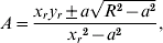


V 1 – the speed of the own ship,
V 2 – the speed of the target ship,
ψ2 – the course of the target ship,
x r, y r – components of the target ship's position in relation to the own ship.
Equation (2) only has solutions if the following three conditions hold:



where (8) results from the condition TCPA>0 (only future domain violations are of interest).
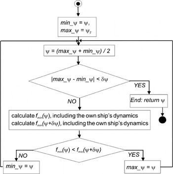
Depending on the obtained values of A and B there may be up to four boundary courses for which DCPA=a, that is up to two course ranges for which DCPA<a. Once a range of courses has been determined, the closest approach course is searched for within this range by means of the bisection algorithm (or by gradient methods). In this phase the own ship's dynamics are taken into account so as to determine the closest approach course precisely. The bisection algorithm is presented in Figure 1. It takes the following input parameters:
• the previously determined range of courses (ψ1, ψ2),
• the accuracy of finding the closest approach course δψ,
• the own ship's turning speed.
Searching for the closest approach course within a given range of courses.

2.2. Determining the range of forbidden courses for a given closest approach course
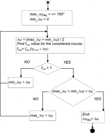
Once a closest approach course has been found, the boundaries of the forbidden sector of the own courses are determined. Figure 2 presents the algorithm of determining the values of the starboard and port board boundaries of the forbidden courses sector. Apart from the standard parameters of both ships the algorithm takes two additional parameters:
• the previously found closest approach course ψ,
• the own ship's turning speed.
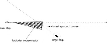
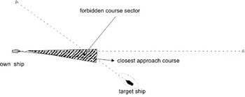
Different results of forbidden course sectors obtained for different own ship domains are shown in Figures 3 and 4 where the forbidden courses for a circle-shaped and off-centred ellipse-shaped target domains respectively are shown.
The algorithms determining the port board and starboard boundaries of the forbidden sector of the own course.

The sector of forbidden own courses for an encounter with a single target for a circle-shaped domain.

The sector of forbidden own courses for an encounter with a single target for an ellipse-shaped domain.

2.3. Determining the optimal course alteration manoeuvre for a multi-target encounter
The optimal course alteration manoeuvre for a multi-target encounter is the alteration which fulfils the following conditions:
• it is compliant with COLREGS [3], that is, it is equal to zero or no less than 15 degrees (or any other predefined value),
• it guarantees a safe passage – the own ship domain will not be violated,
• the altered course is as close as possible to the desired course, that is, to the course directed towards the destination point (or the next turning point of the predetermined route).
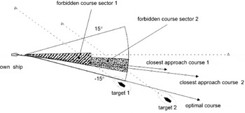
The first two conditions reflect the constraints, the third one – the optimisation criterion. The safety constraints are given as a sequence of forbidden course sectors (possibly overlapping) obtained for all closest approach courses. The COLREGS condition might also be represented by means of forbidden course sectors. It is sufficient to add two extra course ranges to the forbidden course sectors list: (current course −15 degrees, current course) and (current course, current course +15 degrees). This will guarantee that only course alterations larger or equal to 15 degrees will be taken into account. (See Figure 5.)
Overlapping sectors of forbidden own courses for an encounter with two targets and the resulting optimal course of the own ship.

As for the optimisation criterion, it might be observed that the optimal altered course has the following quality: it is either equal to the desired course or equal to one of the boundaries of the forbidden course ranges. Therefore it might be simply determined by the following procedure:
1. Check whether the optimal altered course is equal to the desired course. This can be done by checking whether it lies outside all forbidden course sectors. If it does it is the solution to the task. If it does not the next step has to be applied.
2. Make a list of candidate courses in the following way. For all boundary courses of forbidden course sectors check whether a current boundary course lies outside all other forbidden course sectors. If it does insert it into the candidate list.
3. From the candidate list choose the one which is closest to the desired course. If there are two courses equally close to the desired course: one meaning an alteration to the starboard, the other to the port board, choose the one which crosses astern of the targets (this usually means choosing the alteration to the starboard).
2.4. Determining for how long the altered course has to be kept
Determining for how long the navigator should keep the altered course, before all considered targets are safely passed, is done according to the following algorithm:
1. The targets are arranged in the ascending order of their t min times (times remaining to reaching f min values).
2. For each of the prioritised targets determine the appropriate time by means of the bisection algorithm or gradient method. The time value determined for the current target is passed to the algorithm determining the time for the next target as the parameter t 1. This guarantees that the time value, which is to be determined for the next target, will not be less than the time value that has already been determined for the previous target.
3. Choose the value that has been determined for the last target.
2.5. A simulation example
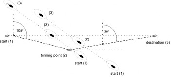
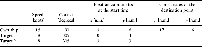
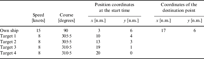
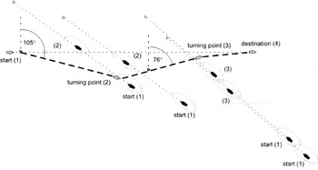
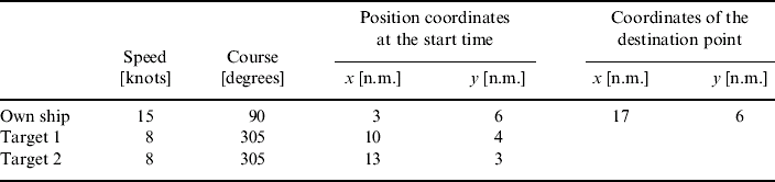
An example trajectory, which is a result of a single course alteration manoeuvre avoiding collision with two targets is exemplified by Figure 6. The numbers in brackets in Figure 6 denote different phases of the situation. The simulation data for this example are provided in Tables 1, 2 and 3.
A trajectory which is a result of a single course alteration manoeuvre avoiding collision with two targets.

Positions, courses and speeds of the own ship and the target ships.
The assumed parameters of the Fuji domain.

The additional configuration parameters.

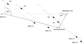
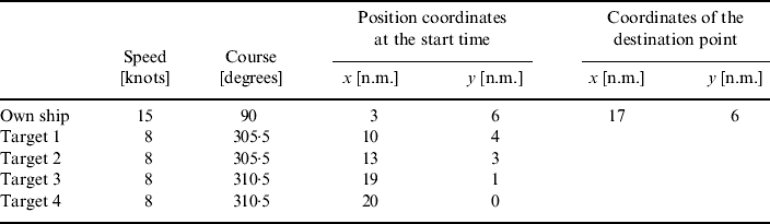
The trajectory in Figure 6 is not only a safe one but for this particular situation it would be also close to the optimal one, because its way loss is insignificant (only 2% of the original trajectory length). However, if the t min values (the times remaining to reaching the f min) varied considerably for different targets, the own ship would have to keep the altered course for much longer thus increasing the way loss. Such situation is shown in Figure 7. The simulation data for this example are provided in Tables 4 and 5.
A trajectory which is a result of a single course alteration manoeuvre avoiding collision with four targets.

Positions, courses and speeds of the own ship and the target ships.
The assumed parameters of an ellipse-shaped domain.

Here the domain is slightly larger with its shape being close to that according to Coldwell [Reference Coldwell1] and there are two more target ships. As a result the own ship keeps the altered course for so long that the resulting way loss is unacceptable (nearly 14% of the original trajectory length). In such situations more than one course alteration manoeuvre should be applied. The method of planning a multi-manoeuvre trajectory is presented in Section 3.
3. PLANNING A SAFE TRAJECTORY
As has been mentioned, traditional methods of determining optimal safe trajectories tend to minimize the economic cost of manoeuvring, while treating safety issues as constraints. This may lead to determining trajectories which contain too many turning points. Such trajectories are not practical for a number of reasons. Therefore it is desired to use a method which simplifies the own trajectory by minimizing the number of turning points and thus makes the own ship's behaviour more predictable for the targets. The proposed approach is to treat the number of manoeuvres as an optimisation criterion and introduce the following optimisation constraints:
• own ship domain cannot be violated,
• the maximum acceptable course alteration cannot be larger than 60 degrees (or any other predefined value),
• the minimum acceptable course alteration cannot be less than 15 degrees,
• the way loss resulting from the manoeuvres is computed according to formula 9. It should not be larger than a given percentage of the original length of a segment of the predetermined route between the two subsequent turning points, that is, a maximal acceptable way loss percentage is given as a constraint.

The simulation results obtained by the author prove that this approach results in trajectories which are both safe and realistic: they keep the way loss reasonably small while containing a fewer number of manoeuvres and thus being understandable for target ships and easy to follow.
3.1. The recursive algorithm of planning a safe trajectory
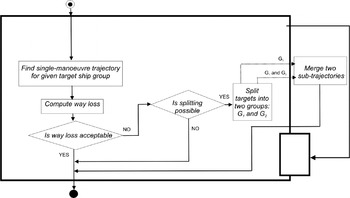
The main idea of the method is as follows:
1. A trajectory resulting from a single collision avoidance manoeuvre is determined.
2. If the way loss of that trajectory is too large, the targets are split into two groups depending on their closest approach times (early encounters and late encounters).
3. Two sub-trajectories are determined. The first one is for avoiding collisions with the first group of targets. The second one is for continuing from the endpoint of the first sub-trajectory to the destination point, while avoiding collisions with the targets from both groups.
4. If the way loss for any of the sub-trajectories is still too large, the sub-trajectory is further split into two sub-trajectories by calling the algorithm recursively.
The method is summarised by the scheme in Figure 8. The detailed description of the recursive algorithm is presented in Appendix A.
The two main operations shown in Figure 8, computing the way loss and splitting the targets into two groups, are described in detail in the following subsections.
The recursive algorithm of planning a safe trajectory. The recurrence (stepping down) is indicated by the rectangle in the bottom right corner.

3.2. Splitting the targets into two groups
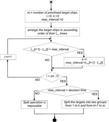
The targets are split on the basis of their encounter times with the own ship tmin. First, all targets are arranged in the ascending order of their tmin values. Then, the two subsequent targets, for which the difference between their tmin values is the largest, are selected. If this difference is less than the user defined decision time, the split operation is not possible. Otherwise it is performed. The first of the abovementioned target ships and all the preceding targets constitute the first group. The second target and all the following ones constitute the second group. This algorithm is presented in Figure 9.
Splitting the targets into two groups.

3.3. Computing the way loss percentage for a trajectory and a sub-trajectory
Computing the way loss percentage for the main trajectory is done according to the already mentioned formula 9. However, in case of a sub-trajectory the variable original_trajectory_length makes no sense, since both the starting and the ending point of a sub-trajectory might be lying out of the original trajectory. Instead the length of the sub-trajectory has to be compared with the distance the own ship covers towards the destination point, while following this sub-trajectory. Therefore the way loss is in this case computed according to the following formulas:
If end_distance−start_distance>0 (the own ship moves towards its destination):

if end_distance−start_distance<=0 (the own ship moves away from its destination):

where:
start_distance – the distance from the destination point at the start of the sub-trajectory,
end_distance – the distance from the destination point at the end of the sub-trajectory.
3.4. A simulation example
An example of applying the method of planning safe trajectories is shown in Figure 10. The data for this has already been presented in Tables 4 and 5. The trajectory contains two course alteration manoeuvres as opposed to the trajectory presented previously in Figure 7. The result is a way loss of less than 5% instead of nearly 14%.
A safe trajectory returned by the proposed method.

4. SUMMARY AND CONCLUSIONS
In this paper a new method of planning collision avoidance manoeuvres for multi-target encounter situations has been introduced. The method is based on an idea of a sequence of the necessary manoeuvres but brings a few considerable improvements. It consists of a set of algorithms of which the most important is the one determining the optimal course alteration for a multi-target encounter. In some situations this algorithm may be directly applied as a stand-alone tool. In others it can be utilized inside a method of planning safe trajectories. Its main advantages are as follows:
— it is compliant with COLREGS and supports any ship domain due to applying the author-designed collision risk measure (DCPA is replaced with the new measure – approach factor f min),
— the targets are handled simultaneously instead of sequentially,
— the method minimizes the number of course alterations thus making the behaviour of the own ship more understandable for targets,
— if the determined way loss is too large, the trajectory is recursively split into sub-trajectories,
— the already passed targets are still taken into account when planning new manoeuvres,
— the method is very fast because of the bisection algorithms that have been used: the computational complexity of the main algorithm is a logarithmic function of the considered time range and linear function of the number of the targets,
— it takes into account the dynamics of the manoeuvres.
The correctness of the method has been verified by the author through a series of simulation experiments involving up to 20 target objects of randomly generated parameters. On a standard PC machine a trajectory would be found in 10 to 90 milliseconds depending on the scenario and the domain used. All of the obtained trajectories were compliant with COLREGS. The average results over the whole population of test scenarios were: the way loss of less than 4% and about 3 course alterations per trajectory. The last result is of great significance, since it proves that it is possible to determine numerically ship trajectories that are navigator-friendly, without sacrificing safety or economy.
5. Appendix A
5.1. The Recursive Algorithm of Planning a Safe Trajectory in Detail
The detailed algorithm of planning a trajectory is given below. It consists of the following steps.
1. Check the parameters of all target ships within range of the ARPA and AIS systems. Prepare two lists of target ships: one containing all of them and the other including only those that have way priority according to COLREGS.
2. If none of the prioritised ships courses collide with the current course of the own ship, there is no need to alter it: follow the previously determined route (exit the scheme). However if there is a non-empty subset of the prioritised ships, whose courses collide with the desired course, go to point 3.
3. Arrange all targets in the ascending order of their t min values.
4. For each target check whether it has way priority, assuming that the own course is equal to the desired course (possibly different from the current course).
5. For each of the prioritised targets find the closest approach courses of the own ship by means of the algorithm presented in Section 2.1.
6. For each of the closest approach courses find the forbidden own course sectors by means of the algorithm presented in Section 2.2.
7. For the already known forbidden course sectors determine the optimal altered course by means of the algorithm presented in Section 2.3. If such course does not exist or the necessary course alteration is larger than the maximal acceptable manoeuvre – go to step 8. If a speed cannot be reduced – report failure and go to step 11. Otherwise go to step 9.
8. Reduce the own speed to the nearest lower speed value. Return to step 5.
9. Determine for how long the altered course has to be kept by means of the algorithms presented in Section 2.4.
10. Save the resulting altered trajectory. Compute the way loss percentage as has been described in Section 3.3. If the way loss is less than the maximal acceptable value, accept the trajectory and go to step 16. Otherwise – go to step 11.
11. Try to split the targets into two groups as described in Section 3.2. If this is not possible accept the already determined trajectory (despite the high way loss percentage) and exit this level of the scheme. Otherwise go to the next step.
12. Call the algorithm again (recursion, entering the lower level of the scheme) for the first group of targets, starting from step 4. Save the returned sub-trajectory.
13. Update the positions of all ships according to the data returned with the first sub-trajectory.
14. Call the algorithm again (recursion, entering the lower level of the scheme) for all targets (the first and the second group of targets put together), starting from step 4. Save the returned sub-trajectory.
15. If both sub-trajectories have been determined successfully, merge them into one trajectory. Compare its length with the previously saved (step 10) length of the altered trajectory. Choose the shorter trajectory. If any of the sub-trajectories has returned failure, the choice is obvious – the previously saved trajectory. If step 10 has been omitted due to the failure during step 7 – choose the merged trajectory.
16. Return the chosen trajectory (or a failure if no valid trajectory is available). If this is the main trajectory or the last sub-trajectory (the one which handles all targets) return full trajectory (the one, which leads directly to the destination point after the last target has been safely passed). Otherwise return only the part responsible for avoiding collisions with the given group of targets.