





Introduction
Breast cancer radiotherapy requires a high level of geometric accuracy to ensure adequate target coverage while minimizing dose to surrounding organs at risk, particularly the heart and lungs. Conventionally, patient positioning for breast radiotherapy has relied on skin marks, either as tattoos or semi-permanent marks aligned with room lasers, followed by image-guided radiotherapy (IGRT) to verify and correct setup errors. While this approach is well established, it is associated with several limitations. Skin marks only represent a single point in relation to the treated area which can be unreliable due to the mobility of the skin as well as variations in arm and breast position. Reference Psarras, Stasinou and Stroubinis1 In addition, permanent tattoos may negatively impact patient experience and post-treatment body image. Reference Landeg, Kirby, Lee, Bartlett and Titmarsh2
The use of surface-guided radiotherapy (SGRT) has increased rapidly in recent years as an alternative to skin-marker setup. SGRT employs reflection of optical light to capture the patient’s 3D surface and is therefore considered non-ionizing and non-invasive. The real-time 3D surface is registered to a reference surface, e.g. from the computed tomography (CT), providing displacement information and positioning possibilities based on a 3D region of interest (ROI) instead of single-point marks. Additionally, SGRT facilitates patient monitoring, enabling intra-fractional detection and correction of patient movement. Several studies have confirmed the efficiency of SGRT for prepositioning of breast patients using three-camera-unit systems like AlignRT (VisionRT Ltd., London, UK) Reference Jimenez, Batin and Giantsoudi3–Reference Cravo Sá, Fermento and Neves7 and Catalyst (C-RAD AB, Uppsala, Sweden). Reference Stanley, Mcconnell, Kirby, Gutiérrez, Papanikolaou and Rasmussen8,Reference Kügele, Mannerberg and Nørring Bekke9
ExacTrac Dynamic® (ETD) (Brainlab, Munich, Germany) provides an SGRT system with a single-camera unit mounted to the ceiling inferior to the couch, and only a limited number of studies have evaluated prepositioning of breast patients treated in free breathing with this system. Reference Katayama, Takahashi and Kitaoka10,Reference Klumpp, Baumbach and Wegner11 None of these studies compared SGRT-based prepositioning with conventional skin mark–based methods; instead, they reported SGRT setup accuracy without reference to previously established positioning techniques. Furthermore, crossover studies evaluating the ETD SGRT system within the same patient population are currently lacking.
The primary aim of this study was therefore to investigate the accuracy of SGRT setup using ETD compared to conventional setup using semi-permanent skin marks in a crossover study design for patients receiving breast radiotherapy in free breathing. The secondary aim was to assess the intrafraction motion using continuous SGRT monitoring during treatment delivery with special attention to movement over time, including potential systematic shifts.
Methods
Twenty individual patients treated with postoperative (lumpectomy) breast radiotherapy in free breathing were included in the study. Six patients had partial-breast irradiation (PBI), and 14 had whole-breast irradiation (WBI), two of whom also received sequential external boost treatment to the tumour bed. One patient was treated with bilateral WBI where each side was treated independently and hence each side was included in the study as different patients in the WBI group, making the total number of patients 21. The patient cohort is summarized in Table 1. The study and patient data acquisition was registered and approved in The North Denmark Region (e-Doc: 2023-012396-67).
Patient cohort

Table 1. Long description
The table presents data on patient types, match strategies, number of patients, fractions, skin-marker fractions, and SGRT fractions. It has five rows and six columns. The columns are labeled Patient type, Match strategy, Patients, Fractions, Skin-marker fractions, and SGRT fractions. The rows are labeled WBI, Boost, PBI, and Total. Row 1: WBI, MV-kV, 15, 255, 96, 159. Row 2: Boost, Clips (kV-kV), 2, 13, 5, 8. Row 3: PBI, Clips (kV-kV), 6, 60, 26, 34. Row 4: Total,, 21, 328, 127 (38.7 percent), 201 (61.3 percent).
Patient cohort including match strategy, number of patients, the total number of fractions and the number of fractions for each setup procedure. See Figure S.1d in Supplementary Material for distribution of fractions per patient.
a Boost plans are not included in the total number of patients as they also received WBI.
Patient setup and treatment
Patients were immobilized in supine position using ConChest Breast Board (Candor, Gislev, Denmark) inclined at an angle of minimum 4° and with both arms above the head. A CT scan was acquired for each patient on a Siemens SOMATOM go. Open Pro (Siemens Healthcare, Erlangen, Germany), reconstructed with 2 mm slice thickness. The CT reference position was marked as three points on the patients with semi-permanent markers: one on the chest midline caudal to the sternum and one on the midaxillary line on both sides of the patient. Treatment plans were simulated in Eclipse treatment planning system v16.1 (Varian Medical Systems, Palo Alto, USA) where target and OARs were delineated according to ESTRO and Danish national guidelines. 12,Reference Offersen, Boersma and Kirkove13 Treatment plans were created using 3D conformal tangential field-in-field planning technique with isocentre placed centrally in the target. Dose prescription was 40 Gy in 15 fractions, and boost plans were delivered sequentially with additional 16 Gy in 8 fractions or 10 Gy in 5 fractions to the tumour bed. Treatments were delivered on Varian TrueBeams v2.7 (Varian Medical Systems, Palo Alto, USA) equipped with on-board MV- and kV-imaging systems and SGRT system ETD v1.1.
Two different setup procedures were investigated as a single-centre crossover study, where both procedures were used for all patients but for different treatment fractions. The setup procedure applied at each fraction was determined by clinical workflow and staff availability, resulting in approximately equal use of skin-marker setup and SGRT setup. For all fractions, patients were initially set up by aligning the CT reference skin marks to the in-room lasers, and then either the skin-marker setup or the SGRT setup was used for prepositioning.
Skin-marker setup
Isocentre skin marks were marked at the first treatment fraction by applying a 3D couch shift from CT reference position to the isocentre according to the plan isocentre coordinates. For the following treatment fractions using skin-marker setup, a manual couch shift was employed to align the isocentre skin marks to the in-room lasers.
SGRT setup
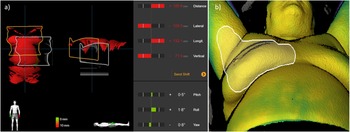
The ETD SGRT system used one camera-unit mounted to the ceiling inferior to the couch. The unit consisted of a projector of structured optical light, two high-resolution cameras and a thermal camera. Structured optical light in a pseudo random pattern was projected onto the patient surface, where the reflections were recorded by the two high-resolution cameras. From the reflections and the known geometry of the imaging system, the patient surface information was obtained as the ETD surface structure. 14 The position of this structure was compared to the planned surface position from the CT scan, and the discrepancy between the two structures was translated into a 6 degrees of freedom (DoF) deviation as illustrated in Figure 1a. The 3D translational couch shift was applied for prepositioning, which was done inside the treatment room.
(a) Prepositioning using ETD SGRT. The white structure is the planned surface position from CT, and the orange structure is the surface position observed by ETD. The bars on the right indicate the couch shift. (b) Combined SGRT and thermal image of a patient with the surface tracking area (STA) used for monitoring patient motion during treatment shown in white.

IGRT and match strategy
IGRT was applied after each setup procedure, utilizing MV-kV images with match to the thoracic wall for WBI patients, and orthogonal kV-kV images with match to the surgical clips for PBI patients and patients treated with a boost. The subsequent applied 3DoF translational couch shift was in each case recorded as the setup offset and used for analysis and evaluation of the two setup procedures.
Statistical analysis
The setup offset was analysed for three translational directions, vertical (VRT), longitudinal (LNG) and lateral (LAT), to determine the accuracy of the two setup procedures. Mean population offset (M) as well as systematic (∑) and random (σ) population errors were calculated for each setup procedure and tested against each other using paired t-test for M and σ and F-test for ∑. 15
Intrafraction motion
For treatment fractions prepositioned with SGRT, real-time monitoring of patient motion (movement and respiration) was enabled during beam delivery. A surface tracking area (STA) was defined as illustrated in Figure 1b, and a surface baseline was captured prior to first beam on. Surface points within the STA were combined to a mean 6DoF shift from baseline which was sampled per monitor unit (MU) and saved in log-files. 14 The total deviations from baseline were evaluated.
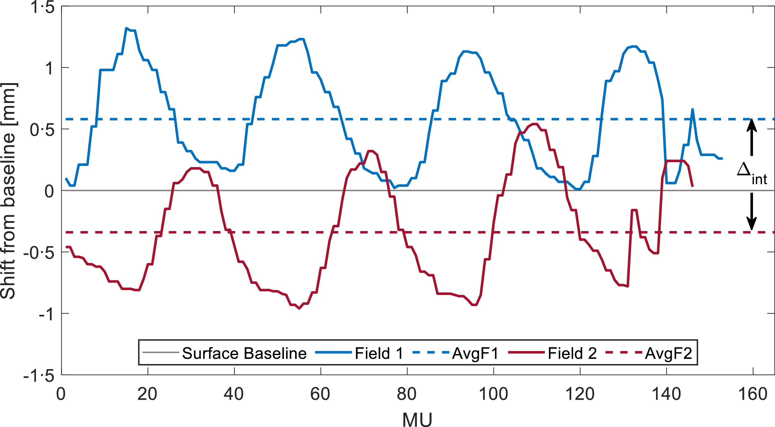
The systematic patient movement, excluding periodic respiration, was analysed by calculating the average shift from baseline in VRT, LNG and LAT for each of the two main fields (AvgF1, AvgF2) for each fraction. The inter-field shift (Δint = AvgF2 – AvgF1) represented the intrafraction movement. This is illustrated in Figure 2. The mean population shift (Mint) was found as well as the systematic (∑int) and random (σint) population shifts. Mint was tested with one-sample t-test.
Example of a surface shift from baseline (in vertical direction) per monitor unit (MU) delivered for the two main fields (blue and red, respectively) of one patient fraction. The dashed lines indicate the average shift for each field (AvgF1 and AvgF2), and the inter-field shift is indicated as Δint.

All data in this study were analysed in MATLAB®, and all tests were two-tailed and evaluated at the 5% significance level.
Results
Prepositioning
The analysis of the setup offset included 328 fractions of which SGRT was used in 201 fractions. When dividing the treatment course into early (fraction 1–7) and late (fraction 8 onwards) treatment fractions, skin-marker setup was used in 62 (49%) and 65 (51%) fractions, respectively, while SGRT was used in 85 (42%) and 116 (58%) fractions, respectively. The average prepositioning 3D couch shift from CT reference to isocentre was 16·8 cm (SD = 1·7 cm).
The mean population offset (M) in the three translational directions showed no significant difference between the two setup procedures, as shown in Table 2. Significant difference was, however, observed for σ in VRT (p = 0·03) and LNG (p = 0·01) and for ∑ in LAT (p = 0·04), with SGRT setup showing smaller errors than skin-marker setup in all cases. Distributions of setup offsets per patient are shown in Supplementary Material (Figure S.1).
Prepositioning setup offset

Long description
A table comparing mean population offset in three translational directions for two setup procedures. The table has four rows and three columns. Column headers are VRT (mm), LNG (mm), and LAT (mm). Row labels are Skin marker and SGRT. Each column is further divided into M (95 percent confidence interval), Σ, and σ. Row 1: Skin marker, VRT (mm): M (-2.6 (-4.1, -1.1)), Σ (3.4), σ (3.5). LNG (mm): M (-0.8 (-2.0, 0.3)), Σ (2.6), σ (3.6). LAT (mm): M (-0.2 (-1.4, 0.9)), Σ (2.5), σ (2.6). Row 2: SGRT, VRT (mm): M (-2.5 (-3.6, -1.5)), Σ (2.3), σ (2.5). LNG (mm): M (-0.6 (-1.5, 0.3)), Σ (2), σ (2.4). LAT (mm): M (-0.9 (-1.6, -0.2)), Σ (1.6), σ (2.1). Row 3: p-value, VRT (mm): M (0.94*), Σ (0.09**), σ (0.03*). LNG (mm): M (0.76*), Σ (0.28**), σ (0.01*). LAT (mm): M (0.22*), Σ (0.04**), σ (0.06*).
IGRT match after prepositioning showing the setup offset using the skin marker vs SGRT procedure in VRT, LNG and LAT directions in terms of mean population offset (M) with 95% confidence interval (95%ci), systematic population error (∑) and random population error (σ). *Paired t-test. ** F-test. All tests are with 5% significance level.
For both procedures, M was significantly different from zero in VRT (p < 0·01), demonstrating a significant offset compared to IGRT, which was also observed for SGRT in LAT (p = 0·02). For SGRT, 76%, 89% and 96% of the fractions were within 5 mm for VRT, LNG and LAT, respectively, while it was 70%, 79% and 86% for skin-marker setup.
Intrafraction motion
The analysis of intrafraction motion included data from 183 fractions. Fractions with incomplete surface data for the two main fields were excluded. One bilateral patient was excluded due to non-compliance with the image guidance procedure as the patient position was corrected after IGRT to account for the contralateral treatment.
The median of the intrafraction motion vector shift from baseline was 0,9 mm with a 95th percentile of 2·9 mm. The proportions of MUs delivered with a displacement exceeding 3 mm from baseline were 0·9%, 1·1% and 0·1% for VRT, LNG and LAT, respectively. Rotations exceeding 1 degree were 1·3%, 1·9% and 0·1% for pitch, yaw and roll.
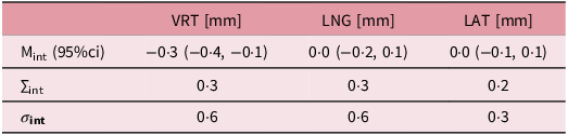
No significant intrafraction movement was observed in LNG and LAT, but a significant mean population shift (Mint) of −0·3 mm (p < 0·01) was observed in VRT (Table 3). An example of an inter-field shift (Δint) of approximately −1 mm is visualized in Figure 2. All systematic and random errors for inter-field shifts were below 0·4 and 0·7 mm, respectively, and the mean (±SD) treatment time from onset of Field 1 to end of Field 2 was 113 ± 36 seconds.
Intrafraction movement

Table 3. Long description
A table with three rows and three columns comparing intrafraction movement in VRT, LNG, and LAT directions. The columns are labeled VRT (mm), LNG (mm), and LAT (mm). The rows are labeled Mint (95 percent CI), Δint, and σint. Row 1: Mint (95 percent CI), VRT (mm): -0.3 (-0.4, -0.1), LNG (mm): 0.0 (-0.2, 0.1), LAT (mm): 0.0 (-0.1, 0.1). Row 2: Δint, VRT (mm): 0.3, LNG (mm): 0.3, LAT (mm): 0.2. Row 3: σint, VRT (mm): 0.6, LNG (mm): 0.6, LAT (mm): 0.3.
Surface-based intrafraction movement in VRT, LNG and LAT directions described by the mean population shift between the two main fields (Mint) with 95% confidence interval (95%ci). The inter-field systematic (∑int) and random (σint) errors are also shown.
Discussion
This study investigated the accuracy and consistency of patient prepositioning using SGRT with the Brainlab ETD single-camera-unit system compared to traditional skin-marker setup. The SGRT setup was performed with an average vector shift of 16·8 cm from CT reference to isocentre which illustrated that patients could be positioned relatively far away from the treatment position prior to the SGRT setup procedure.
The study showed no significant difference in patient setup accuracy between the two setup procedures. However, SGRT demonstrated significantly lower systematic and random population errors compared to skin-marker setup, indicating improved consistency as the variations were reduced.
Our findings are comparable with previous studies evaluating the accuracy of ETD-based SGRT for breast radiotherapy. Katayama et al. Reference Katayama, Takahashi and Kitaoka10 reported average offsets of –2·8 mm, –2·2 mm and 0·3 mm in VRT, LNG and LAT, respectively, when comparing SGRT with kV–kV imaging. Similarly, Klumpp et al., Reference Klumpp, Baumbach and Wegner11 comparing SGRT with CBCT, reported that 72% of translational deviations in the thoracic region were within 5 mm, with the largest variations observed in VRT and LNG. Both studies showed larger offsets in VRT and LNG, but we only observed the large offset in VRT. Since this VRT offset was observed for both SGRT (−2·6 mm) and skin-marker (−2·5 mm) setup, it could be attributed to a systematic offset to our patient cohort or clinic. The negative values indicate couch correction in the anterior direction leading to an interpretation of patient relaxation between initial positioning and IGRT.
Since none of the previous ETD-based SGRT studies, to our knowledge, have compared SGRT to skin-marker setup, the present study addresses a clear gap in literature. While this is a tentative interpretation given our limited sample size, it suggests that vertical offsets observed in ETD-based SGRT may be influenced more by patient- or clinic-specific factors than by the technical limitations of the single-camera system.
Several studies evaluating three-camera SGRT systems such as AlignRT and Catalyst have compared surface-guided setup with tattoo- or skin-marker–based positioning. Reference Svestad, Heydari, Mikalsen, Flote, Nordby and Hellebust5–Reference Kügele, Mannerberg and Nørring Bekke9 Our results are consistent with these reports, which generally conclude that SGRT matches or surpasses the accuracy of conventional skin-marker setup. Reviews by Naidoo et al. Reference Naidoo and Leech16 and Psarras et al. Reference Psarras, Stasinou and Stroubinis1 reported mean setup offsets ranging from –3·1 to 4·6 mm for tattoos/skin marks and from –3·2 to 3·0 mm for SGRT. The setup offsets observed in our study fall within these ranges, indicating that the performance of the single-camera-unit SGRT system from ETD is comparable to that reported for multi-camera SGRT systems. While multi-camera systems provide greater surface coverage and redundancy, the present results suggest that the more limited surface acquisition of ETD did not adversely affect setup performance for breast radiotherapy in free breathing.
A strength of this study is the crossover design, which minimizes interpatient variability and enhances the robustness of the comparison relative to retrospective analyses using separate patient cohorts. The study included 21 patients and was not powered to detect small differences between the setup procedures. Formal randomization was not applied, resulting in an unbalanced distribution of fractions, with SGRT used in approximately two-thirds of the fractions due to clinical workflow considerations. This represents a limitation of the study. Nevertheless, the distribution of skin-marker setup and SGRT procedures between early and late treatment fractions remained balanced, suggesting limited temporal bias.
SGRT reduced the proportion of fractions exceeding 5 mm (24% versus 30% for skin-marker setup in VRT), where 5 mm corresponded to the clinically applied PTV-margin. Despite this improvement, a substantial number of fractions still required correction following IGRT. Thus, while SGRT represents a reliable alternative to conventional skin-marker setup, daily IGRT is still advisable, as has also been suggested by multiple studies Reference Svestad, Heydari, Mikalsen, Flote, Nordby and Hellebust5–Reference Cravo Sá, Fermento and Neves7 and international guidelines. Reference Mast, Leong and Korreman17
Intrafraction motion was evaluated for all delivered monitor units and was generally small. The median vector shift was 0·9 mm, with 95% of observations below 2·9 mm. Only a small proportion of delivered monitor units was observed exceeding 3 mm in any translational direction, and rotations greater than 1° were rare. These findings indicate a high degree of positional stability during treatment delivery. A 3 mm tolerance could therefore be considered an appropriate threshold for surface-guided beam hold to avoid irradiation at larger deviations while minimizing unnecessary beam interruptions.
Our results are consistent with previous studies evaluating SGRT monitoring for breast radiotherapy. Reference Hattel, Andersen, Wahlstedt, Damkjær, Saini and Thomsen6,Reference Reitz, Carl and Schönecker18–Reference Malone, Ryan and Nicholson20 Hattel et al., Reference Hattel, Andersen, Wahlstedt, Damkjær, Saini and Thomsen6 using AlignRT for surface monitoring, reported a median vector shift of 1.1 mm, with displacements exceeding 3 mm in 1.8%, 1.8% and 0% of the observations for VRT, LNG and LAT, respectively. Reitz et al. Reference Reitz, Carl and Schönecker18 evaluated 2028 treatment sessions using the Catalyst SGRT system and observed a median vector shift of 0,78 mm. Both studies demonstrated intrafraction motion of similar magnitude to that observed in the present study.
Katayama et al. Reference Katayama, Takahashi and Kitaoka10 demonstrated a strong correlation between ETD surface monitoring and EPID breast position verification, supporting the ability of a single-camera-unit SGRT system to provide a reliable surrogate for breast position. This strengthens the interpretation of the present findings. It should be noted that the definition of the STA may influence reported motion metrics, as the selected region determines the calculated mean deviation from baseline, as has also been pointed out in previous studies. Reference Psarras, Stasinou and Stroubinis1,Reference Malone, Ryan and Nicholson20 As the primary focus of the present study was prepositioning accuracy, the STA was defined as illustrated in Figure 1b, but minor variations between patients may have influenced the intrafraction motion results.
By analysing the positional difference between the two main fields, we were able to evaluate the patient movement, excluding the periodic respiration. No significant shift was observed in the longitudinal or lateral directions. However, a small but statistically significant vertical shift of −0.3 mm was detected, corresponding to a couch correction in the anterior direction. A systematic shift from baseline was also described by Wiant et al., Reference Wiant, Wentworth, Maurer, Vanderstraeten, Terrell and Sintay19 who reported a significant correlation between baseline shift and increasing treatment time in a cohort of 30 patients. Although our treatment times were relatively short (113 ± 36 s), the observed vertical shift is consistent with the hypothesis that patient relaxation may contribute to vertical displacement. Importantly, while the shift reached statistical significance, its magnitude was small relative to typical setup uncertainties and is therefore not clinically relevant.
In general, the intrafraction motion was limited, but occasionally larger deviations above 3 mm were observed. This study therefore highlights the value of continuous surface monitoring, as it enables detection of patient movement that would otherwise remain unobserved. Despite the modest sample size and exclusion of fractions with incomplete surface data, the findings support SGRT as a sensitive and practical tool for intrafraction motion monitoring.
Conclusion
Surface-guided setup using ETD showed no significant difference in accuracy compared to conventional skin-marker setup, but it did show reduced systematic and random errors indicating improved consistency. Subsequent IGRT is, however, advisable for final patient positioning. We demonstrated that ETD SGRT was able to track patient motion effectively.
Supplementary material
The supplementary material for this article can be found at https://doi.org/10.1017/S1460396926100569.
Data availability statement
The data that support the findings of this study are available from the corresponding author, T.K., upon reasonable request.
Acknowledgements
None.
Author contributions
T.K., M.S.N., I.J. and T.O.K. conceived the study design and data acquisition. T.K. and M.S.N. performed analysis. All authors were involved in data interpretation. T.K. wrote the manuscript draft. All authors reviewed and approved the final manuscript.
Financial support
This work did not receive funding from public or private entities.
Competing interests
The authors report there are no competing interests to declare.
Declaration of AI-assistance in the writing process
During the preparation of this work, the author used ChatGPT-4 and ChatGPT-5 to improve language and readability. After using this tool/service, the author reviewed and edited the content as needed and takes full responsibility for the content of the publication.
Ethical standards
The study and patient data acquisition was registered and approved in The North Denmark Region (e-Doc: 2023-012396-67).




 Open access

