1. Introduction
Alignment is the process whereby the orientation of the axes of a strapdown inertial navigation system (SINS) is determined with respect to the reference axis system (Titterton and Weston, Reference Titterton and Weston2004). Initial alignment of SINS at sea is one of the difficult issues of navigation (Titterton and Weston, Reference Titterton and Weston2004). In conventional methods, angular velocity and gravity vector information are used to calculate initial conditions. When a ship is moored, due to the movement of waves, the output of the gyroscopes becomes disturbed, thereby making it difficult to derive the angular velocity of the Earth. Therefore, the usual methods for situations where there are high external disturbances are not suitable. In these conditions, the use of gravity information in the inertial frame improves the time and accuracy. In general, initial alignment algorithms for SINS at sea consist of two main parts: coarse and fine alignment algorithms (Gu et al., Reference Gu, El-Sheimy, Hassan and Syed2008). In the case of initial alignment at sea, due to the nonlinear equations and the large initial heading error, a coarse alignment prior to a fine alignment is usually used to apply the equation linearisation methods to the precise initial alignment process (Sun and Sun, Reference Sun and Sun2010). The aim is to reduce the initial input error to the precise process. The allowed range of an initial heading error existing in a precise linearised algorithm is usually considered to be a few degrees (Gu et al., Reference Gu, El-Sheimy, Hassan and Syed2008). In the initial alignment process of navigation systems in the case of using nonlinear equations without linearisation, the coarse alignment process can be neglected. Of course, the lower the initial heading error existing in the fine alignment process, the less time it takes to obtain the desired heading precision. In the literature there are generally two methods for calculating the matrix of initial conditions: the dual vector method and Wahba's least squares estimation method (Zhao et al., Reference Zhao, Guan, Cheng, Xu and Fei2016). In the dual vector method, the velocity vector pairs in the physical frame and the integral of gravitational acceleration in the inertial frame are used and the calculations are performed algebraically. In Wahba's method, the least squares estimation is used to calculate the initial alignment quaternions with the minimum variance in the adaptation of the velocity vector of the physical frame and the integral of gravitational acceleration in the inertial frame. With these two methods, different filters are commonly used to smooth and eliminate disturbances. The coarse initial alignment approach is mainly based on the measurement of gravitational acceleration changes to estimate the heading angle. Extensive discussions on the idea of alignment have been based on the observation of the gravitational apparent motion. The initial alignment method with vector operations is based on the geometric relationship between motion vectors at different moments. In this method, the direct cosine matrix between the inertial and the navigation coordinates is obtained through vector operations. The direct cosine matrix between the body and the navigation coordinates is then determined. In this method too, the accuracy of the initial alignment is affected by the measurement noise. The amplitude of the noise increases as the vectors are subtracted. In the literature, the low-pass filter was used for the measured data and good results were obtained. However, finding low-pass filters for all environments with synthetic noise is a difficult task.
In Sun and Sun (Reference Sun and Sun2010) the initial alignment for the SINS uses pure gravity displacement in the inertial coordinates. In this structure, the output gyroscope is first used to trace the body coordinates. Then the measurement of the accelerometer is imaged in inertial coordinates to determine the direction of the apparent gravity motion. Based on vector calculations on this route, the direct cosine matrix between the inertial and navigation coordinates is calculated. In order to correctly identify the pure gravity motion from the measurement of the accelerometers involving random noise, in addition to avoiding collinear vectors in vector operations, a reconstruction algorithm for identifying parameters and extracting the pure gravity is designed and simulated (Tan et al., Reference Tan, Zhu, Su, Wang, Wu and Gu2015).
This paper proposes a new solution for the initial alignment of SINS at sea. In this method, the apparent motion of gravity is used in the inertial frame, and circular fitting is used to find the direct cosine matrix between the navigation and the body frame. What distinguishes the proposed method from other methods is that the calculations of the initial alignment are performed directly from the angle between the circles related to the gravitational apparent motion. Typical methods use a data derivative which has many problems, but the proposed method does not require the use of a data derivative. The simulation and test results show that the proposed alignment method can be used in mooring conditions.
The remainder of this paper is structured as follows. In Section 2, reference coordinates frames are defined. In Section 3, the principles of the proposed initial alignment are outlined. In Section 4, the proposed circular fitting problem is fully examined. Section 5 describes how to extract the direct cosine matrix from the fit circles. In Sections 6 and 7, the simulation and test results are analysed. Section 8 summarises and concludes.
2. Reference frame definitions
The reference frames used in this paper are as follows:
A. Body coordinate frame (b): The origin of this frame is centred on the centre of the vehicle. Its
 ${x_b}$ axis points forward, and its ${z_b}$ axis points downward. The ${y_b}$ axis is determined by the right-hand rule.
B. Navigation coordinate frame (n): The origin of this frame is centred on the centre of the vehicle. Its
${x_n}$ axis points to the north. Its ${y_n}$ axis points east. The ${z_n}$ axis is pointing downward.C. Inertial coordinate frame (i): The axes of this frame are defined orthogonally and with the right-hand rule. This frame is fixed to the inertial space. The
${i_{b0}}$ coordinate frame is an inertial frame that is defined at the first moment to match the body frame.D. Earth coordinate frame (e): A rotating coordinate system with the Earth whose
${z_e}$ axis corresponds to the axis of rotation of the Earth and whose ${x_e}$ and ${y_e}$ axes are on the plane of the Earth's equator.


3. Principle of coarse alignment
Gravitational apparent motion is defined as the track of gravity at a fixed point rotating with the Earth when the observation is processed in an inertial frame (Liu et al., Reference Liu, Xu, Zhao, Wang and Liu2014).
The direct cosine matrix, between body and navigation frame, can be described as follows:
 \begin{equation}C_b^n = C_e^nC_i^e C_{ib0}^i C_b^{ib0}\end{equation}
where  $C_b^{ib0}$ is the direct cosine matrix between the body frame b and the inertial frame
 ${i_{b0}}$ and can be achieved using the output of gyroscopes (the output of gyroscopes is the angular velocity of a body with respect to inertia). Its initial value, according to the frame definition, is:
 \begin{equation} C_b^{ib0}(0 )= {I_{3 \times 3}}\end{equation}
Also,  $C_e^n$ according to the frame definition is as follows:
 \begin{equation}C_e^n = \left[ {\begin{matrix} { - \sin L}&0&{\cos L}\\ 0&1&0\\ { - \cos L}&0&{ - \sin L} \end{matrix}} \right]\end{equation}
and  $C_i^e$:
 \begin{equation}C_i^e = \left[ {\begin{matrix} {\cos {\omega_{ie}}t}&{\sin {\omega_{ie}}t}&0\\ { - \sin {\omega_{ie}}t}&{\cos {\omega_{ie}}t}&0\\ 0&0&1 \end{matrix}} \right]\end{equation}
where  ${\omega _{ie}}$ is the Earth's rotational rate.
Because the i frame and the  ${i_{b0}}$ frame are both inertial frames, the relationship between them is unchanged with time. Thus,
 $C_{ib0}^i$ is a constant matrix. In order to find
 $C_b^n$ matrix, only
 $C_{ib0}^i$ is unknown.
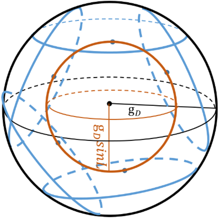
As the Earth moves from west to the east, the apparent of gravity anywhere on the Earth is a cone. In this paper, we define a new vision of gravity motion. If we see the three-dimensional space of gravity vector parametric change in an inertial frame: (1) with Equations (1–4) the parametric trajectory of gravity vector is a circle; (2) because the magnitude of gravity in all frames is constant, this circle is on the surface of a sphere; (3) the radius of the sphere is the magnitude of gravity  ${\textrm{g}_D}$ and its centre is the origin; (4) the radius of the circle is
 ${\textrm{g}_D}\sin L$ with L being the latitude; (5) the centre of the circle is on the surface of another sphere with radius
 ${\textrm{g}_D}\cos L$; (6) in inertial space, a circle in
 ${i_{b0}}$ inertial frame is rotated towards the circle in
 $\textrm{ }i$ inertial frame.
With orientation of  ${i_{b0}}$ frame parametric circle with respect to
 $\textrm{ }i$ frame parametric circle in inertial space, the direct cosine matrix between these two frames can be calculated.
The gravity vector in the inertial frame is:
 \begin{equation}{\textrm{g}^i} = C_n^i{\textrm{g}^n},\,{\textrm{g}^n} = {\left[ {\begin{matrix} 0&0&{{\textrm{g}_D}} \end{matrix}} \right]^T}\end{equation}
According to Equation (5), we can calculate the parametric motion of gravity in i frame with no need for accelerometer data.
 \begin{equation}{\textrm{g}^i} = C_n^i\left[ {\begin{matrix} 0\\ 0\\ {{\textrm{g}_D}} \end{matrix}} \right] = \left[ {\begin{matrix} { - \hbox{cos}\, L\cos {\omega_{ie}}t}\\ { - \hbox{cos}\, L\sin {\omega_{ie}}t}\\ { - \hbox{sin}\, L} \end{matrix}} \right]{\textrm{g}_D}\end{equation}
and:
 \begin{equation}{f^{ib0}} = C_b^{ib0}{f^b}\end{equation}
where  ${f^b}$ is the output of accelerometers in the body frame. With Equation (6) and Figure 1 we have the i frame parametric circle:
 \begin{equation}\begin{cases} {\textrm{g}_x^i(t )= -
{\textrm{g}_D}\cos L\cos {\omega_{ie}}t }\\
{\textrm{g}_y^i(t )= - {\textrm{g}_D}\cos L\sin
{\omega_{ie}}t }\\
{\textrm{g}_z^i(t )= -
{\textrm{g}_D}\sin L} \end{cases}
\end{equation}
Parametric motion of gravity in the inertial frame in different circles caused by different initial Euler angles. The circles and their centres are on the surface of two spheres

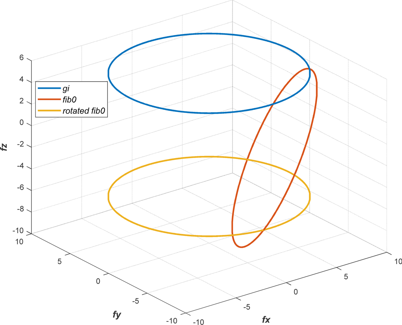
Because of the shape in  ${i_{b0}}$ frame, and according to Figure 2 only rotated respect to circle of i frame, this shape is a circle and with equation (6) we see that the rotation of
 ${\textrm{g}^i}$ is the linear combination of
 $\left[ {\begin{matrix} {\cos {\omega_{ie}}t}&{\sin {\omega_{ie}}t}&1 \end{matrix}} \right]$. As a result, the general equation of the
 ${i_{b0}}$ frame parametric circle is:
 \begin{equation}\left\{
{\begin{matrix} {f_x^{ib0}(t )= {A_1}\cos {\omega_{ie}}t +
{B_1}\sin {\omega_{ie}}t + {C_1} }\\ {f_y^{ib0}(t )=
{A_2}\cos {\omega_{ie}}t + {B_2}\sin {\omega_{ie}}t +
{C_2}}\\ {f_z^{ib0}(t )= {A_3}\cos {\omega_{ie}}t +
{B_3}\sin {\omega_{ie}}t + {C_3}} \end{matrix}}
\right.\end{equation}
 ${g^i}$,
 ${f^{ib0}}$ and rotated
 ${f^{ib0}}$ circles in inertial frame.
 ${f^{ib0}} $ for
 $\psi = {30^\circ }$,
 $\varphi = {7^\circ }$ and
 $\theta = {10^\circ}$ initial angle of SINS

The purpose of the next section of this paper is to find the unknown parameters of Equation (9) and then to directly calculate the direct cosine matrix between these two inertial frames.
4. Parametric circle fitting in space
In this section, we want to find  ${f^{ib0}}$ parameters from measurement data.
 ${f^{ib0}}$ data are in a plane with noise and perturbations. To find parametric circle estimation:
A. The plane containing the
${f^{ib0}}$ points is estimated.B. The points are transferred to a vertical normal vector plane (finding a direct cosine matrix for this transformation).
C. With nonlinear least square error method, parameters for nonlinear circle fitting are estimated.
D. Parametric circle equation is transferred to the original plane.

The novelty of this paper in estimating this parametric circle is the point-to-point transfer to the parametric circle. This process has been done by adding an initial phase to the estimated circle in Section 4.3.
4.1 Finding the plane containing the ${f^{ib0}}$ points

In general,  ${f^{ib0}}$ points are on a plane. Suppose that the plane equation is as shown below:
 \begin{equation}Ax + By + Cz = 1\end{equation}
With m points, to calculate the plane parameters:
 \begin{equation}[{A B C} ]{\left[ {\begin{matrix} {f_x^{ib0}({{t_i}} )}\\ {f_y^{ib0}({{t_i}} )}\\ {f_z^{ib0}({{t_i}} )} \end{matrix}} \right]_{3 \times m}} = {[1 ]_{1 \times m}}\end{equation}
Parameters A, B and C are elements of the normal vector ( $N$) of the plane. Using the linear least square error method, we can estimate the plane parameters.
4.2 Transferring the plane
The normal vector of the estimated plane must be rotated, where only the third element has a nonzero value. To transform the plane to a horizontal plane, we must find the transformation matrix that changes the plane normal vector to a vertical vector. For this purpose, we use QR factorisation for the normal vector. The QR factorization is a linear algebra operation that factors a matrix into an orthogonal component, which is a basis for the row space of the matrix, and a triangular component. In this case, vector  ${R_{3 \times 1}}$ becomes an upper triangular matrix (only the first element of its three elements is nonzero) and
 ${Q_{3 \times 3}}$ matrix is an orthogonal transformation matrix.
 \begin{equation}{N_{3 \times 1}} = {Q_{3 \times 3}}{R_{3 \times 1}}\end{equation}
Now, by changing the column of matrix Q, we have matrix U, which transforms the plane normal vector to a vertical vector.
 \begin{equation}U = {\left[ {\begin{matrix} {{Q_2}}&{{Q_3}}&{{Q_1}}\\ \downarrow & \downarrow & \downarrow \end{matrix}} \right]^T},UN = vertical\end{equation}
Since the normal vector becomes vertical by the U transformation matrix, if  ${f^{ib0}}$ points multiply to this matrix (U), the points plane transforms to a plane that is parallel to the
 ${x_e}{y_e}$ plane.
4.3 Estimation of parametric circle equation
The parametric equation of the circle on the two-dimensional space is defined as follows:
 \begin{equation}\begin{matrix} {x = {x_0} + r\cos ({\omega t + {\varphi_0}} )}\\ {y = {y_0} + r\sin ({\omega t + {\varphi_0}} )} \end{matrix}\end{equation}
Since the points are estimated one by one in time, it is possible that the points have a rotation; therefore, we placed the initial phase in Equation (14). The values of  ${x_0}$ and
 ${y_0}$ are zero, and we know the value of the radius, so in Equation (14) we only need to find the phase of the parametric circle.
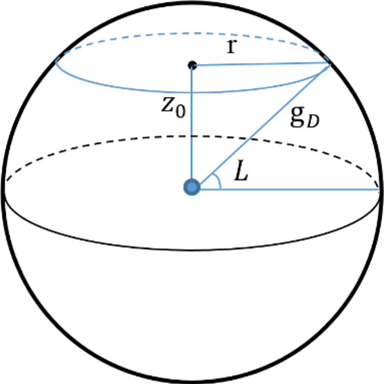
By considering the constant gravitational vector, and according to Figure 3 the radius of the circle is computed through the following equation.
 \begin{equation}\begin{aligned} {z_0} &={-} {\textrm{g}_D}\sin L\\ r &= \sqrt {{\textrm{g}_D}^2 - {z_0}^2} = |{{\textrm{g}_D}\cos L} |\end{aligned}\end{equation}
The radius of parametric motion of gravity circle in inertial frame

Then, we solve the nonlinear least square problem using the Gauss-Newton method (Nelles, Reference Nelles2002). With the assumption:
 \begin{equation}\begin{matrix} {f{1_i} = {x_{i1}} - x({{\varphi_0}} )}\\ {f{2_i} = {x_{i2}} - y({{\varphi_0}} )} \end{matrix}\end{equation}
and
 \begin{equation}f = {\left[ {\begin{matrix} {\begin{matrix} {f{1_1}}\\ \vdots \\ {f{1_m}} \end{matrix}}\\ {\begin{matrix} {f{2_1}}\\ \vdots \\ {f{2_m}} \end{matrix}} \end{matrix}} \right]_{2m \times 1}}\end{equation}
The distance of  ${d_i}$ from
 $p_i\left( {x_{i1},x_{i2}} \right)$ is:
 \begin{equation}d_i^2 = [{{{({f{1_i}} )}^2} + {{({f{2_i}} )}^2} } ]\end{equation}
Finally,  ${\varphi _0}$ is obtained from minimising the following cost function:
 \begin{equation}\mathop \sum \limits_{i = 1}^m d_i^2 = min\end{equation}
The Jacobean matrix is constructed as:
 \begin{equation}J = {\left[ {\begin{matrix} {\begin{matrix} {\dfrac{{\partial f{1_1}}}{{\partial {\varphi_0}}}}\\ \vdots \\ {\dfrac{{\partial f{1_m}}}{{\partial {\varphi_0}}}} \end{matrix}}\\ {\begin{matrix} {\dfrac{{\partial f{2_1}}}{{\partial {\varphi_0}}}}\\ \vdots \\ {\dfrac{{\partial f{2_m}}}{{\partial {\varphi_0}}}} \end{matrix}} \end{matrix}} \right]_{2m \times 1}}\end{equation}
Hence, using the Gauss-Newton method we have:
 \begin{equation}{\varphi _0}_k = {\varphi _0}_{k - 1} - h{({J_{k - 1}^T{J_{k - 1}}} )^{ - 1}}J_{k - 1}^T{f_{k - 1}}\end{equation}
In which h is step parameter, and using the recursive method we could compute  ${\varphi _0}$. For the initial value of
 ${\varphi _0}$ we can calculate the mean values of
 ${x_i}$ and
 ${y_i}$ for some seconds of time and the initial value of
 ${\varphi _0}$ is obtained from the following equations:
 \begin{equation}\begin{aligned} {x_{im}} &= \frac{{\mathop \sum \nolimits_{i = 1}^m {x_i}}}{m} ,\quad {y_{im}} = \frac{{\mathop \sum \nolimits_{i = 1}^m {y_i}}}{m}\\ {\varphi _0}_0 &= {{\tan }^{ - 1}}\left( {{y_{im}},{x_{im}}} \right) \end{aligned}\end{equation}
Because the Gauss-Newton optimisation method is a local method, there may be many global solutions to the problem. When using a local optimisation method, the desired convergence occurs if the initial values selected are appropriate. In this case, because the initial phase is approximately approximate according to Equation (22), the local optimisation method provides a good answer and there is no need for global optimisation methods.
If the number of the points used in the initial alignment is less than 5 min, the computed initial value for  ${\varphi _0}$ is sufficient and using the Gauss-Newton method does not improve the accuracy of the alignment.
Now, all the parameters in Equation (14) are determined. Using triangular equations, we have:
 \begin{equation}\begin{matrix} {{x_i} = {x_0} + r\cos {\omega _{ie}}{t_i}\cos {\varphi _0} - r\sin {\omega _{ie}}{t_i}\sin {\varphi _0}}\\ {{y_i} = {y_0} + r\sin {\omega _{ie}}{t_i}\cos {\varphi _0} + r\cos {\omega _{ie}}{t_i}\sin {\varphi _0}} \end{matrix}\end{equation}
and parametric equations of the circle in the horizontal plane are obtained. This equation is transformed to the main plane by using the inverse of the transformation matrix in Equation (13):
 \begin{equation}{\textrm{g}^{ib0}} = {U^T}\left[ {\begin{matrix} {{x_0} + r\cos {\omega_{ie}}{t_i}\cos {\varphi_0} - r\sin {\omega_{ie}}{t_i}\sin {\varphi_0}}\\ {{y_0} + r\sin {\omega_{ie}}{t_i}\cos {\varphi_0} + r\cos {\omega_{ie}}{t_i}\sin {\varphi_0}}\\ {{z_0}} \end{matrix}} \right]\end{equation}
and the favourite parametric equations are obtained.
5. Calculating the direct cosine matrix
We can rewrite the parametric  ${\textrm{g}^i}$ equation as the following:
 \begin{equation}{\textrm{g}^i} = \underbrace{{\left[ {\begin{matrix} { - {\textrm{g}_D}\cos L}&0&0\\ 0&{ - {\textrm{g}_D}\cos L}&0\\ 0&0&{ - {\textrm{g}_D}\sin L} \end{matrix}} \right]}}_{{{C_{\textrm{g}i}}}}\left[ {\begin{matrix} {\cos {\omega_{ie}}t}\\ {\sin {\omega_{ie}}t}\\ 1 \end{matrix}} \right]\end{equation}
Also the parametric equation of  ${\textrm{g}^{ib0}}$ is:
 \begin{equation}{\textrm{g}^{ib0}} = {U^T}\underbrace{{\left[ {\begin{matrix} {r\cos {\varphi_0}}&{ - r\sin {\varphi_0}}&{{x_0}}\\ {r\sin {\varphi_0}}&{r\cos {\varphi_0}}&{{y_0}}\\ 0&0&{{z_0}} \end{matrix}} \right]}}_{{{C_{\textrm{g}ib0}}}}\left[ {\begin{matrix} {\cos {\omega_{ie}}t}\\ {\sin {\omega_{ie}}t}\\ 1 \end{matrix}} \right]\end{equation}
and we have:
 \begin{equation}{\textrm{g}^{ib0}} = C_i^{ib0}{\textrm{g}^i}\end{equation}
By substitution we reach:
 \begin{equation}{C_{gib0}}\left[ {\begin{matrix} {\cos {\omega_{ie}}t}\\ {\sin {\omega_{ie}}t}\\ 1 \end{matrix}} \right] = C_i^{ib0}{C_{gi}}\left[ {\begin{matrix} {\cos {\omega_{ie}}t}\\ {\sin {\omega_{ie}}t}\\ 1 \end{matrix}} \right]\end{equation}
As a result:
 \begin{equation}{C_{\textrm{g}ib0}} = C_i^{ib0}{C_{\textrm{g}i}}\end{equation}
Finally:
 \begin{equation}C_i^{ib0} = {C_{\textrm{g}ib0}}\textrm{ }{C_{\textrm{g}i}}^{ - 1}\end{equation}
and the unknown direct cosine matrix of section 3 is obtained. Now we have transferred the matrix from the body to the navigation frame in the first instance from the following equation:
 \begin{equation}C_b^n(0 )= C_i^n(0 )\textrm{ }C_{ib0}^i\textrm{ }C_b^{ib0}(0 )\end{equation}
and we have:
 \begin{equation}\begin{aligned} &C_b^{ib0}(0 )= I\\ &C_i^n(0 )= C_e^n = \left[ {\begin{matrix} { - \sin L}&0&{\cos L}\\ 0&1&0\\ { - \cos L}&0&{ - \sin L} \end{matrix}} \right] \end{aligned}\end{equation}
As a result:
 \begin{equation}C_b^n(0 )= \left[ {\begin{matrix} { - \sin L}&0&{\cos L}\\ 0&1&0\\ { - \cos L}&0&{ - \sin L} \end{matrix}} \right]C_{i}^{ib0T}\end{equation}
By determining this matrix, the initial Euler angles are determined.
6. Simulation
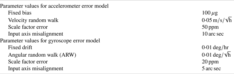
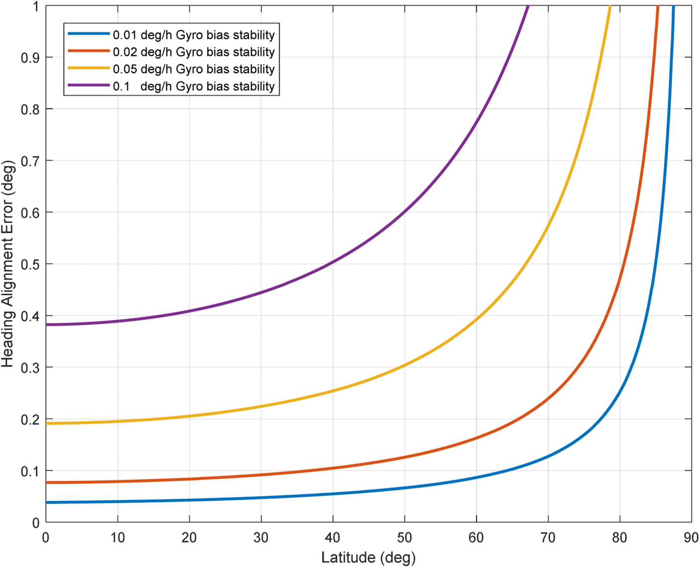
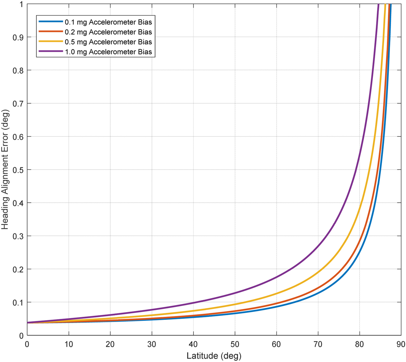
In the case of initial alignment at sea using inertial sensors, the accuracy to be achieved depends on many parameters. Among these parameters are the specifications of the inertial sensors used. For this research, the important parameters are specified in Table 1 and it is assumed that the calibration compensations are performed thoroughly on the sensors. This calibration compensation can be done using methods such as those in Rahimi and Nikkhah (Reference Rahimi and Nikkhah2020). Another parameter is the time required to achieve the desired accuracy. As time goes on, accuracy usually approaches the accuracy of static environmental conditions. Another important parameter is the amount of turbulence due to the environmental conditions of the sea. Achieving the desired accuracy is an important issue in different sea conditions. In the initial alignment based on the specifications of the sensors, the achievable accuracy based on the latitude is determined by Equation (34) (Titterton and Weston, Reference Titterton and Weston2004).
 \begin{equation}\Delta \psi = \frac{{{b_{gyro}}}}{{{\omega _{ie}}}}SecL + \frac{{{b_{acc}}}}{\textrm{g}}\tan L\end{equation}
where  ${b_{gyro}}$ is the gyroscope bias,
 ${b_{acc}}$ is the accelerometer bias, L is the test position latitude,
 ${\omega _{ie}}$ is the magnitude of the angular velocity of the Earth,
 $\textrm{g}$ is the magnitude of the gravitational acceleration at the test position, and
 $\Delta \psi $ is the initial alignment heading angle error.
Parameter values for IMU error model

Based on Equation (34) and also based on the accelerometer specifications mentioned in Table 1, for different bias stability values of gyroscopes, accuracy can be achieved in the heading angle, as shown in Figure 4. Also based on Equation (34) and based on the gyroscope specifications mentioned in Table 1, for different bias values of accelerometers, accuracy can be achieved in the heading angle as shown in Figure 5.
The accuracy that can be achieved in the heading angle, for different bias stability of gyroscopes

The accuracy that can be achieved in the heading angle, for different bias of accelerometers

As shown in Figures 4 and 5, for 35 degrees latitude (test position) and for 0⋅01 degrees per h gyroscope bias stability and 0⋅1 mg accelerometer bias (according to Table 1), the expected accuracy at the heading angle is 0⋅05 degrees. To verify the proposed algorithm a simulation was conducted.
6.1 Sensor model
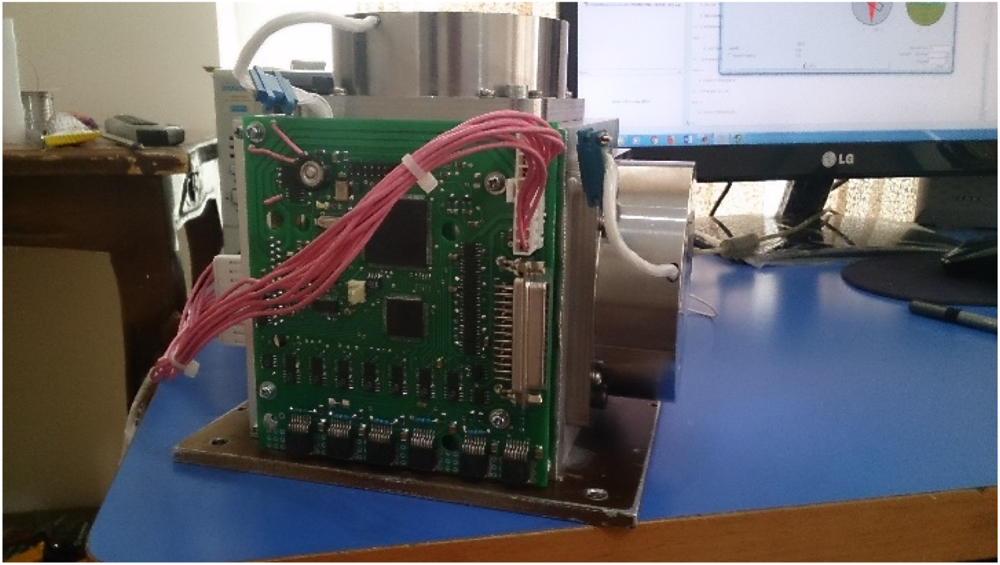
The model of inertial measurement unit (IMU) used in our simulation has parameters as shown in Table 1. The IMU used in this test is based on the specifications of Table 1 and was constructed by the electronics centre of K. N. Toosi University of Technology. It is shown in Figure 6.
K. N. Toosi IMU FOG gyroscopes and Q-FLEX accelerometers (Rahimi et al., Reference Rahimi and Nikkhah2020), with details in Table 1

6.2 Sea turbulence model
In order to simulate the designed algorithm, there is a need for a model of sea turbulence. Different models have been suggested for this purpose in the literature. In this section, the models used in some papers are presented and one of them is selected for use in this research. In Gu et al. (Reference Gu, El-Sheimy, Hassan and Syed2008) it is assumed that the ship is in an anchorage and the angles of its heading, pitch and roll are changed as follows:
 \begin{equation}\begin{aligned}
{\psi } &= {{30}^\circ } + {5^\circ }\cos \left(
{\dfrac{{2\pi }}{7}t + \dfrac{\pi }{3}} \right)\\
{\theta } &= {7^\circ }\cos \left( {\dfrac{{2\pi
}}{5}t + \dfrac{\pi }{4}} \right)\\
\phi &= {{10}^\circ }\cos \left( {\dfrac{{2\pi }}{6}t +
\dfrac{\pi }{7}} \right)
\end{aligned}\end{equation}
where ψ is the heading angle, θ is the pitch angle and φ is the roll angle. Also, its velocity changes as follows
 \begin{equation}{V_{{D_i}}} = {A_{{D_i}}} + {\omega _{{D_i}}}\textrm{ cos}({{\omega_{{D_i}}}t + {\varphi_{{D_i}}}} )\end{equation}
where  $ i = x\textrm{,}y\textrm{,}z$,
 ${A_{{D_x}}} = 0{\cdot}02m$,
 ${A_{{D_y}}} = 0{\cdot}03m$,
 ${A_{{D_z}}} = 0{\cdot}3m$,
 ${\omega _{{D_i}}} = 2\pi /{T_{{D_i}}}$,
 ${T_{{D_x}}} = 7s$,
 ${T_{{D_y}}} = 6s$,
 ${T_{{D_z}}} = 8s$ and
 ${\varphi _{{D_i}}}$ is considered a normal distribution in the interval
 $\left[ {\begin{matrix} 0&{2\pi } \end{matrix}} \right]$. Perturbation velocities due to high frequency vibrations are considered as follows:
 \begin{equation}{V_{D{H_i}}} = \frac{{{A_{D{H_i}}}}}{{2\pi {f_{D{H_i}}}}} + \textrm{ cos}({2\pi {f_{D{H_i}}}t + {\varphi_{D{H_i}}}} )\end{equation}
where  $i = x\textrm{,}y\textrm{,}z$,
 ${A_{D{H_x}}} = 4{\cdot}2\textrm{g}$,
 ${A_{D{H_y}}} = 3{\cdot}8\textrm{g}$,
 ${A_{D{H_z}}} = 4{\cdot}0\textrm{g}$,
 ${f_{D{H_x}}} = 300Hz$,
 ${f_{D{H_y}}} = 250Hz$,
 ${f_{D{H_z}}} = 400Hz$ and
 ${\varphi _{D{H_i}}}$ is considered a normal distribution in the interval
 $\left[ {\begin{matrix} 0&{2\pi } \end{matrix}} \right]$.
In Sun and Sun (Reference Sun and Sun2010) it is assumed that the ship is at anchor and the angles of its heading, pitch and roll are changed as follows:
 \begin{equation}\begin{aligned}
{\psi } &= {{10}^\circ }\cos \left( {\dfrac{{2\pi
}}{6}t} \right)\\
{\theta } &= {6^\circ }\cos \left(
{\dfrac{{2\pi }}{8}t} \right)\\
\phi &= {{12}^\circ }\cos
\left( {\dfrac{{2\pi }}{{10}}t} \right)
\end{aligned}\end{equation}
where ψ is the heading angle, θ is the pitch angle and φ is the roll angle. Also, its velocity changes as follows:
 \begin{equation}{V_i} = {A_i} + \frac{{2\pi }}{{{T_i}}}\cos \left( {\frac{{2\pi }}{{{T_i}}}t + {\varphi_i}} \right)\end{equation}
where  $ i = x\textrm{,}y\textrm{,}z$ means the north, east and down in the navigational frame, and
 ${A_x} = 0{\cdot}02\,m$,
 ${A_y} = 0{\cdot}02\,m$,
 ${A_z} = 0{\cdot}35\,m$,
 ${T_x} = 7\,s$,
 ${T_y} = 6\,s$,
 ${T_z} = 8\,s$, and
 ${\varphi _i}$ is a normal distribution in the interval
 $\left[ {\begin{matrix} 0&{2\pi } \end{matrix}} \right]$.
Gao et al. (Reference Gao, Ben, Zhang, Li and Yu2011) also provide a model that is almost the same as that of Sun and Sun (Reference Sun and Sun2010). In Chang et al. (Reference Chang, Hu, Li and Qin2013), only the attitude model is pointed out. Because of the validity and completeness of the simulation in Gu et al. (Reference Gu, El-Sheimy, Hassan and Syed2008), their model is used in this paper for simulations.
6.3 Wahba's method
To compare the proposed method with the conventional least square method, Wahba's method is used in this section. Grace Wahba proposed the Wahba issue in 1965 (Wahba, Reference Wahba1965). This problem, a weighted least square, is used to calculate the initial quaternion in the alignment of navigation systems, and is as follows:
Consider a set of m points:
 \begin{equation}\{{{v_1},{v_2}, \ldots ,{v_m} } \}\ and\ \{{{w_1},{w_2}, \ldots , {w_m} } \}\ m \ge 2\end{equation}
where  ${v_i}$ points are in the first frame and
 ${w_i}$ points are in the second frame. We want to find a conversion matrix from first frame to second frame through the least square method. Find the conversion matrix R such that it minimises the following weighted error function:
 \begin{equation}er{r^2} = \frac{1}{2} \mathop \sum \limits_{i = 1}^m {a_i}||{R{v_i}} - { {{w_i}} ||^2} \end{equation}
where  ${a_i}$ is a non-negative weight,
 ${v_i}$ and
 ${w_i}$ are vectors. For our problem, the two categories of vectors are the acceleration of the body frame and the acceleration vector in the navigation frame. Weights can be considered as unit.
There are many ways to solve this problem of least squares weighted error. The Q-Davenport method is one of the best ways to solve this problem. This method is computationally stable and does not create a singularity. This method uses quaternion to determine the attitude (Markley and Mortari, Reference Markley and Mortari1999). By sorting the Wahba error function quadratically, the situation becomes such that the error function becomes as follows:
 \begin{equation}er{r^2}(q )= {q^T}Kq \end{equation}
where in:
 \begin{align}K &= \left[ {\begin{matrix} \sigma &{{z^T}}\\ z&{B + {B^T} - \sigma I} \end{matrix}} \right] \end{align}
 \begin{align}z &= \mathop \sum \limits_{i = 1}^m {v_i} \times {w_i} \end{align}
 \begin{align}B &= \mathop \sum \limits_{i = 1}^m {v_i}{w_i}^T \end{align}
 \begin{align}\sigma &= trace(B ) \end{align}
The quaternion that minimises this weight function is the eigenvector resulting from the largest positive eigenvalue of the matrix K.
6.4 Static simulation
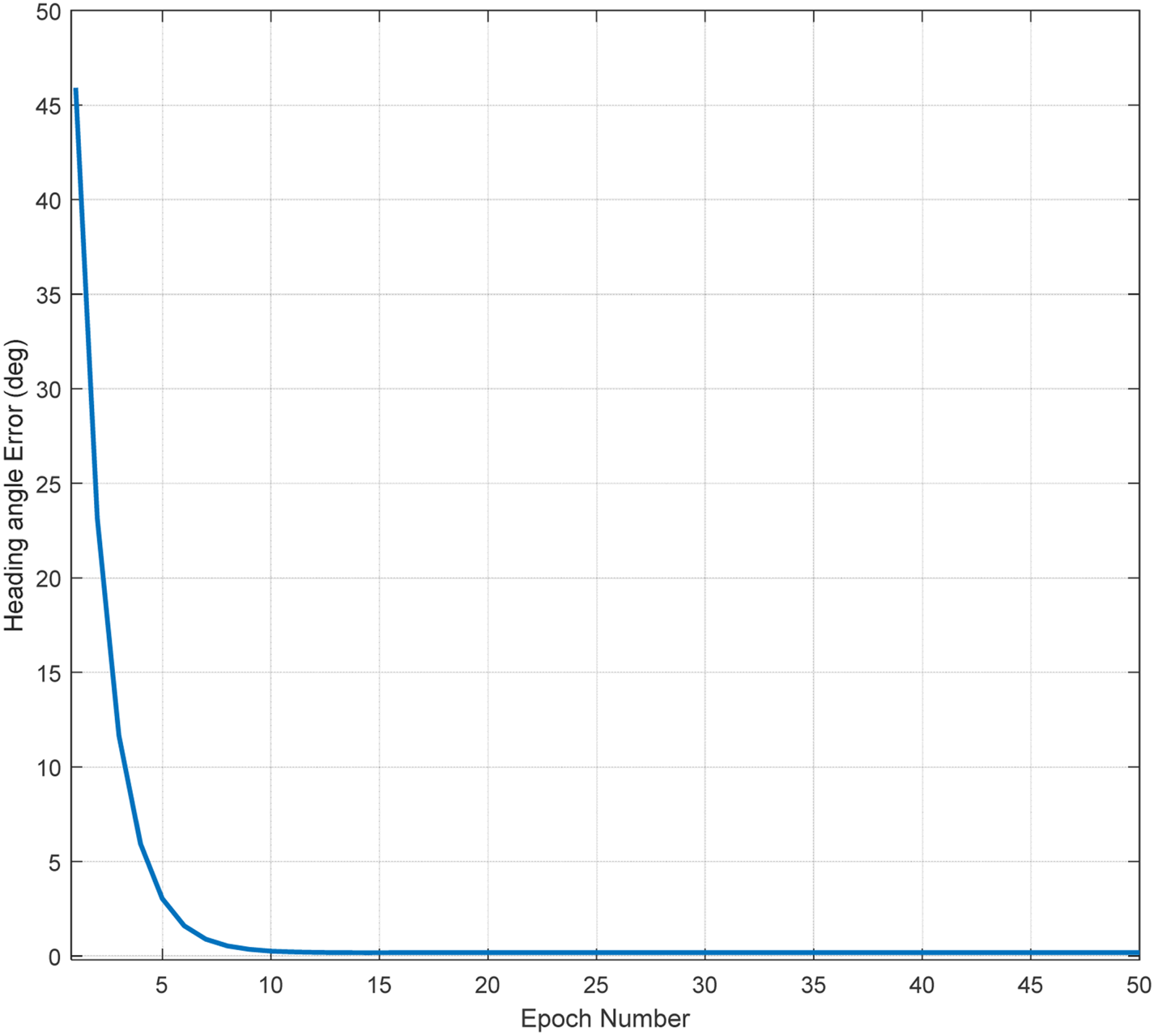
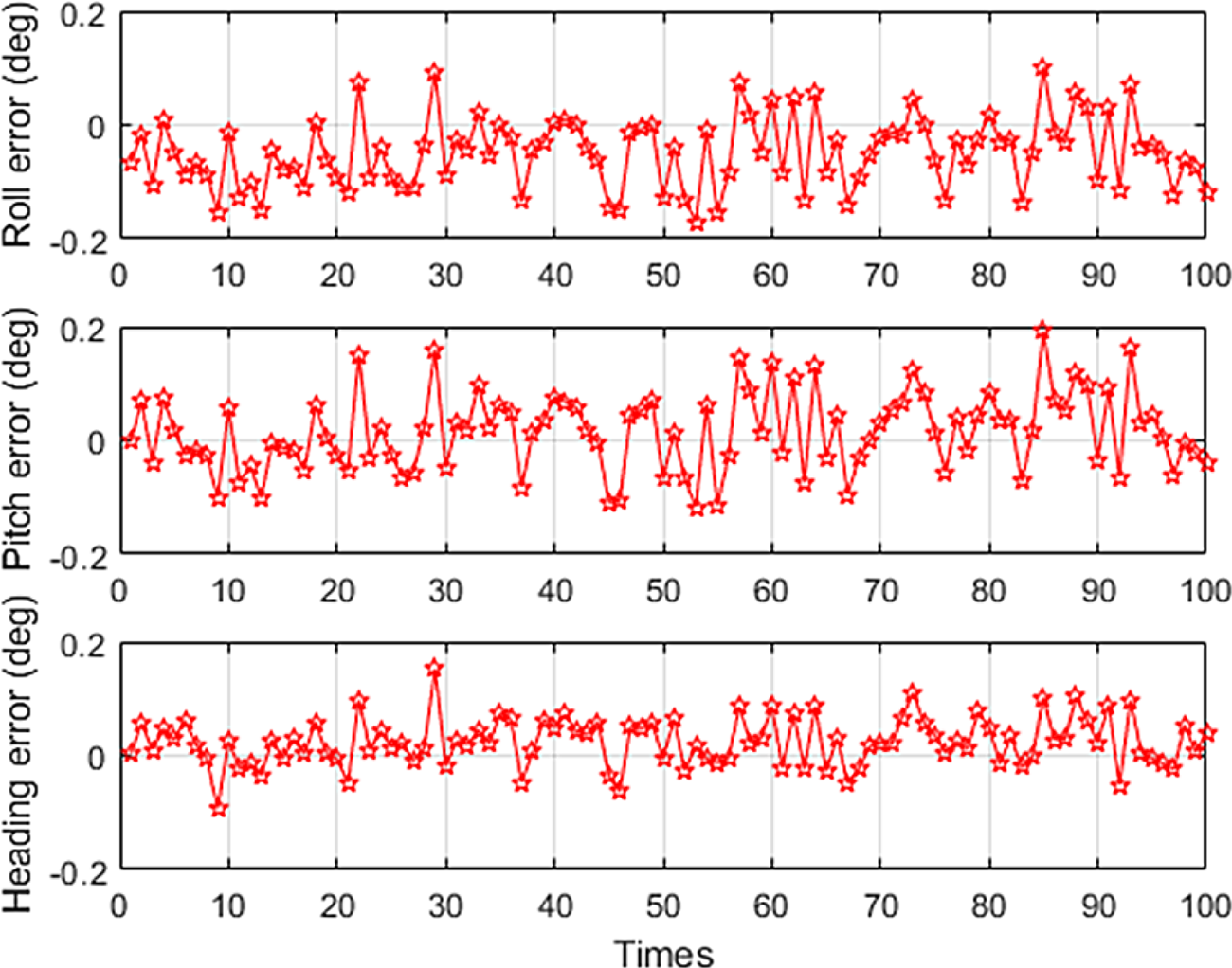
To understand the results of the proposed algorithm, in the first step we assume that the conditions are static and we have only the IMU sensor errors. Data update rate is 100 Hz and we use 200 s data for 100 simulation runs. Given that the proposed algorithm uses the Gauss-Newton nonlinear estimation method to find the phase angle of rotation, the convergence trend of phase angle error for static test is shown in Figure 7. As can be seen from Figure 7, full convergence has occurred after 20 epochs. Figure 8 shows the result of initial angle error for 100 simulation runs.
Trend of convergence of phase angle error for static testing

Initial angles error of the proposed coarse alignment for 100 simulation runs in static conditions

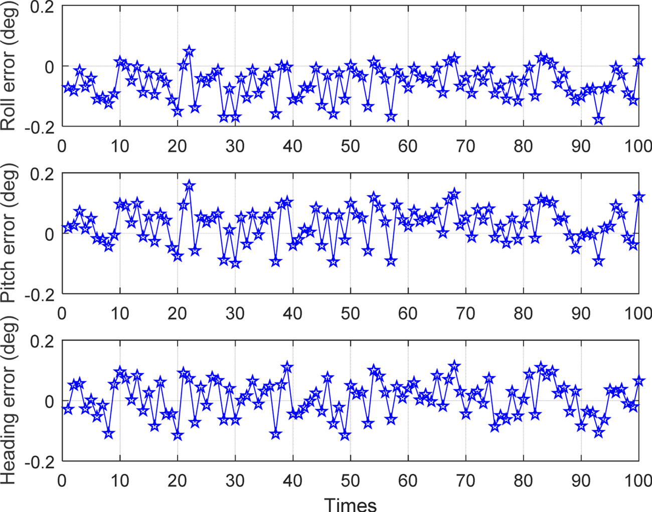
Figure 9 shows the result of initial angle error for 100 simulation runs in static condition with Wahba's method.
Initial angles error of Wahba's method alignment for 100 simulation runs in static conditions

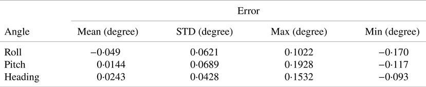
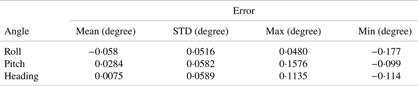
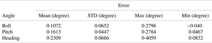
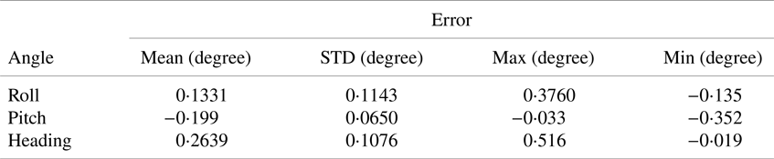
The proposed algorithm error statistics are listed in Table 2. The Wahba's method error statistics are listed in Table 3. The simulation results of the proposed method in static conditions are not improved compared with Wahba's method. In addition, the proposed method does not improve on the usual methods of static conditions.
Statistics for proposed algorithm static simulation results

Statistics for Wahba's method static simulation results

6.5 Mooring simulation
In the simulation, it is assumed that the ship is in moored condition, and we have the IMU sensor errors. Data update rate is 100 Hz and we use 200 s data for 100 simulation runs. Given that the proposed algorithm uses the Gauss-Newton nonlinear estimation method to find the phase angle of rotation, the convergence trend of phase angle error for mooring testing is shown in Figure 10.
Trend of convergence of phase angle error for mooring test

As can be seen from Figure 10, full convergence has occurred after 20 epochs. Figure 11 shows the results of the initial angle error for 100 mooring simulation runs. Figure 12 shows the results of initial angle error for 100 simulation runs in mooring condition with Wahba's method. Mooring simulation error statistics are listed in Table 4. Mooring simulation error statistics with Wahba's method are listed in Table 5.
Initial angles error of the proposed coarse alignment for 100 simulation runs in mooring conditions

Initial angles error of Wahba's method alignment for 100 simulation runs in mooring conditions

Statistics for mooring simulation results

Statistics for Wahba's method mooring simulation results

In the simulation of the moored state, the proposed method has a few improvements compared with Wahba's method.
7. Mooring experiment
To verify the coarse alignment algorithm, practical experiments were conducted. The IMU with Table 1 parameters is used for this purpose. In order to validate the proposed algorithm, a test is performed with the turntable. We run the turntable 15 times for the simulation of mooring conditions. Data update rate is 100 Hz and we use 200 s data. The roll, pitch and heading errors of the initial alignments are shown in Figure 13.
Initial angles error of the proposed coarse alignment for 15 test runs in mooring conditions

Figure 14 shows the result of initial angle error for 15 runs in mooring condition with Wahba's method.
Initial angles error of Wahba's coarse alignment for 15 test runs in mooring conditions

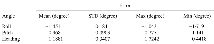
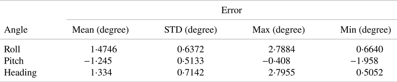
In this section, a two-axis turntable has been used. IMU is installed on this turntable. Before moving the turntable, the initial values of the angles are specified. Further, the mooring movements of the sea are performed on the turntable. At the end of the time, the initial values of the angles extracted from the algorithm are compared with the initial angles of the table and the errors are extracted. The error statistics are listed in Table 6. Mooring condition error statistics with Wahba's method are listed in Table 7.
Statistics for proposed algorithm mooring results

Statistics for Wahba's method mooring results

From Figure 13 and Table 6, it is clear that the attitude and heading errors of the initial coarse alignment are less than 1⋅8 degrees and hence fulfil the requirement for the initial coarse alignment of navigation systems. The reason for the worse results from tests compared with simulations is probably the IMU calibration errors, as well as the nonlinear parameters of the IMU.
In the simulation of mooring conditions with the two-axis turntable, the proposed method has a few improvements relative to Wahba's method.
In the proposed initial alignment process, these three parameters should always be considered:
A. Environmental conditions
B. The degree of accuracy
C. The time of initial alignment.
A change in any one of the above parameters usually causes a change in the others. For example, increasing the initial alignment time reduces the effects of environmental conditions, and as a result, the accuracy of the proposed algorithm increases and approaches the expected accuracy according to the sensor specifications. In addition, if the environmental conditions change, in order to keep the accuracy constant, it is necessary to change the time of the initial alignment.
Because the proposed algorithm is coarse and the accuracy is sufficient up to a few degrees, a fixed time of 5 min is considered and as a result, the accuracy of the algorithm results changes according to different sea conditions. It is clear that in the test environmental conditions, accuracy increases with increasing initial alignment time. However, with more increase of time, the accuracy depends only on the specifications of the sensors used, and with increasing time, there is not much increase in accuracy.
8. Conclusions
When a ship is moored, the method of static ground coarse alignment cannot be used in the marine SINS. Therefore, the initial alignment with the classic method leads to an inaccurate calculation of the initial attitude angles. This paper proposes a new approach for marine SINS coarse alignment. Using the parametric motion of the gravity vector properties in the inertial frame with the circular path of the motion and characteristics like radius and centre of the parametric circle, the initial direct cosine matrix was estimated using the nonlinear least square error method with suitable accuracy. Since the variation of gravity is disregarded in the proposed method, the sensor noise does not have an effect on the accuracy, and the results of the attitude and heading computation are improved. The results of the simulation and mooring experiments indicate that the novel proposed method is effective for coarse alignment in mooring conditions.