I. INTRODUCTION
Cold spray is an advanced coating and repair technology classified as a solid-state thermal spray process (Singh et al., Reference Singh, Kumar and Singh2022). Unlike conventional thermal spray techniques, cold spray operates below the melting temperature of the feedstock material. It accelerates metallic or composite powders to supersonic velocities (typically 300–1,200 m/s) using a high-pressure gas stream, such as nitrogen or helium (Kosarev et al., Reference Kosarev, Klinkov, Alkhimov and Papyrin2002). Upon impact with the substrate, the particles undergo plastic deformation, promoting bonding through mechanical interlocking and metallurgical mechanisms, without significant thermal input (Assadi et al., Reference Assadi, Gatner, Stoltenhoff and Kreye2003). One of the key advantages of cold spray is its ability to deposit coatings with minimal thermal effects, preserving the microstructure and properties of both the substrate and the feedstock material. This prevents oxidation, phase transformations, and undesirable residual stresses, making it particularly suitable for temperature-sensitive materials such as titanium alloys, aluminum, and polymers (Poza and Garrido-Maneiro, Reference Poza and Garrido-Maneiro2022). Additionally, cold spray allows for the deposition of thick layers (up to several millimeters) in a single step, achieving high deposition efficiency and low porosity (Li et al., Reference Li, Gazquez, Borisevich, Mishra and Flores2018). These characteristics make it an ideal technique for applications such as component repair, additive manufacturing, and protective coatings against corrosion and wear. However, cold spray also has its limitations. The requirement for high-pressure gas systems adds complexity and increases equipment costs. Additionally, achieving sufficient adhesion on hard substrates can be challenging unless specific surface preparation, such as grit blasting or polishing, is applied. Furthermore, not all materials are suitable for deposition; while ductile metals and alloys perform well, brittle materials present challenges due to their limited ability to undergo plastic deformation upon impact. Despite these drawbacks, cold spray remains a versatile and promising technology, gaining increasing adoption in industries such as aerospace, automotive, and energy.
High-entropy alloys (HEAs), also known as multi-principal element alloys, are an emerging class of metallic materials that offer a compelling alternative to traditional alloys in advanced engineering applications (Cantor, Reference Cantor2020; Yeh et al., Reference Yeh, Chen, Lin and Chen2007). Unlike conventional alloys, which are typically based on a single principal element – commonly referred to as the “solvent” – HEAs consist of five or more elements in near-equiatomic or high-concentration ratios, typically ranging from 5 to 35 at.% (Martin et al., Reference Martin, Salvo, Pio and Aguilar2021). Due to the stabilizing effect of configurational entropy, HEAs tend to form solid solutions (SSs) or amorphous phases rather than intermetallic (IM) compounds. These solid-solution phases commonly adopt simple crystal structures such as face-centered cubic (FCC), body-centered cubic (BCC), or hexagonal close-packed arrangements (Balaji and Anthony Xavior, Reference Balaji and Anthony Xavior2024). This intrinsic phase stability, combined with synergistic interactions among elements, enables HEAs to exhibit exceptional mechanical, physical, and chemical properties (Gao et al., Reference Gao, Yeh, Liaw and Zhang2016; Lu et al., Reference Lu, Dong, Jiang, Wang, Li and Zhang2015; Zhang et al., Reference Zhang, Gao, Liaw and Yeh2016). Notably, HEAs demonstrate an outstanding balance of high strength, excellent ductility, and superior wear and corrosion resistance, making them highly suitable for applications in extreme environments (Edalati et al., Reference Edalati, Floriano, Tang and Edalati2020; Gorr et al., Reference Gorr, Müller, Azim and Heilmaier2017; Odetola et al., Reference Odetola, Babalola, Afolabi and Olubambi2024; Vaidya et al., Reference Vaidya, Muralikrishna and Murty2019; Ye et al., Reference Ye, Wang, Lu, Liu and Yang2016; Youssef et al., Reference Youssef, Zaddach, Niu, Irving and Koch2015; Yu et al., Reference Yu, Zhang, Cheng, Zhang, Ma, Li, Li, Liaw and Liu2016; Zeng et al., Reference Zeng, Man, Bai and Zhang2021). Their remarkable thermal stability and oxidation resistance have generated significant interest in high-temperature applications, including aerospace components, turbines, and energy-generation systems (Bai et al., Reference Bai, Ding, Hu, Yang, Fan and Liu2021; Yao et al., Reference Yao, Qiao, Gao and Zhang2016, 2017). Additionally, certain HEAs have demonstrated biocompatibility, making them suitable for use in medical implants and devices (Shi et al., Reference Shi, Yang and Liaw2017).
One of the most promising applications of HEAs is the development of advanced coatings to enhance the surface properties of engineering components (Özbilen et al., Reference Özbilen, Vasquez, Abbott, Yin, Morris and Lupoi2023). The unique characteristics of single-phase FCC HEAs, including high hardness and excellent adhesion properties, make them ideal candidates for surface engineering technologies. Among the various deposition techniques, cold spray stands out as a particularly advantageous method for applying HEA coatings (Mengiste et al., Reference Mengiste, Arab, Chen and Xie2025). The absence of significant heating during deposition prevents oxidation, preserves the microstructure of the HEA particles, and ensures strong adhesion to the substrate (Fan et al., Reference Fan, Chen, Ju, Rafferty, Lupoi, Kong, Xie and Yin2024). Mengiste et al. (Reference Mengiste, Arab, Chen and Xie2025) investigated the effect of cold-spray deposition parameters on the wear performance of CrMnFeCoNi and reported a coefficient of friction of 0.30 with a wear rate of 5.10 × 10⁻⁵. Similarly, Fan et al. (Reference Fan, Chen, Ju, Rafferty, Lupoi, Kong, Xie and Yin2024) studied the solid-state deposition of CoCrFeNiMo x (x = 0, 0.2, 0.5, and 1.0), providing further insights into the impact of molybdenum content on coating properties. The HEA showed an SS with FCC crystal structure and hard brittle phases. The CoCrFeNiMo1.0 showed the lowest specific wear rate of 5.1 × 10⁻⁵ mm3/N m, which is smaller than 95% with HEA alloy without Mo.
X-ray diffraction (XRD) profile analysis is a powerful tool currently used for characterizing material microstructures (Mittemeijer and Scardi, Reference Mittemeijer and Scardi2004). The broadening of diffraction profiles is typically attributed to factors such as (a) a reduction in the size of coherent diffraction domains (commonly referred to as crystallite size in nanostructured materials) and (b) the presence of crystalline defects, including stacking faults, microstrain, and dislocations. The contribution of the size of coherent diffraction domains and microstrain (caused by crystalline defects) to the broadening of XRD profiles can be separated because the size of coherent diffraction domains is independent of the diffraction order, unlike strain. There are several methods to determine crystallite size and microstrain, such as the Warren–Averbach method (Warren, Reference Warren1959), the Williamson–Hall method (Williamson and Hall, Reference Williamson and Hall1953), the Rietveld refinement (Rietveld, Reference Rietveld1969), and modified versions of the Warren–Averbach and Williamson–Hall methods (Ungár and Borbély, Reference Ungár and Borbély1996). From XRD profile data, a comprehensive characterization of material structures can be achieved. Information that can be obtained includes (a) the size of coherent domains (or crystallite size) (Dercz et al., Reference Dercz, Matula and Dercs2017), (b) strain, (c) dislocation density, (d) stacking fault probability, (e) twinning probability, (f) coherent domain size distribution, (g) average distance between dislocations, (h) dislocation arrangement parameters, (i) stacking fault energy, (j) lattice parameter, (k) texture, and (l) phase identification (Ungár, Reference Ungár2007). XRD provides a detailed understanding of the microstructural changes induced by the cold-sprayed deposition process of HEA coatings. The rapid plastic deformation and high strain rates during cold spray can alter the microstructure, refine grains, and introduce residual stresses, all of which can be detected through XRD patterns. Broadening of diffraction peaks can be analyzed to estimate the crystallite size and microstrain within the coating, offering insights into the degree of grain refinement and lattice distortion caused by particle impacts (Fan et al., Reference Fan, Chen, Ju, Rafferty, Lupoi, Kong, Xie and Yin2024). Furthermore, XRD can be used to quantify residual stresses in the coating, which significantly influence the coating’s mechanical performance and adhesion to the substrate. Mengiste et al. (2025) reported microstrain values of 3.6 × 10⁻² for a cold-sprayed coating of CrMnFeCoNi. Wei et al. (Reference Wei, Cojocaru, Aghasibeig, Shao, Li, Zhang, Irissou and Zou2024) reported the presence of texture in the cold-sprayed coating of AlCoCrFeNi alloy, specifically in the (200) and (220) peaks of the FCC solid-solution phase. Fan et al. (Reference Fan, Chen, Ju, Rafferty, Lupoi, Kong, Xie and Yin2024) reported XRD pattern broadening due to the reduction in crystallite size and the increase in microstrain in the cold-sprayed coating of the CoCrFeNiMo alloy.
The aim of this manuscript is to characterize HEA powder (CrFeCoNi) as cold-sprayed coatings. XRD pattern analysis was applied to characterize the microstructure of both the raw HEA powder and the cold-sprayed coating. Rietveld refinements were performed using the Materials Analysis Using Diffraction (MAUD) software (Lutterotti et al., Reference Lutterotti, Matthies and Wenk1999).
II. EXPERIMENTAL METHODS
A. Metallurgical design of alloys
In this work, an HEA was chosen according to the following metallurgical criteria:
(a) Microstructure: A microstructure composed of a single phase with an FCC crystal structure is preferred for cold-spray deposition. This is because powders with an FCC crystal structure can undergo greater plastic deformation during deposition, which enhances the efficiency of the process.
(b) Thermodynamics analysis: The High-Entropy Alloys Predicting Software (HEAPS) (Martin et al., Reference Martin, Salvo, Pio and Aguilar2021), accessible at www.rpm.usm.cl, was employed to select the alloy for this study. HEAPS is an open-source, user-friendly tool designed for the exploration and design of HEAs. By leveraging both physical and semi-empirical parameters, it predicts phase formation in alloys. Users can evaluate individual alloys or multiple compositions through its intuitive graphical interface or script-based functions. The software streamlines the screening process by forecasting the microstructure, which includes predicting single-phase solid solution (SPSS) microstructures, lattice structures, and the formation and classification of IM compounds, all based on a wide range of semi-empirical parameters. The classification of criteria used in HEAPS is as follows: (i) microstructure classification (MC), which categorizes microstructures based on whether they consist of an SPSS, SSs, or contain at least one IM phase; (ii) lattice structure solid solution (LSS), which groups criteria related to predicting the lattice structure of the SS; (iii) intermetallic formation (ImF), which focuses on criteria for predicting the formation of specific IM compounds; and (iv) functional and mechanical properties (FMPs), which groups criteria for predicting the FMPs of HEAs.
To determine the formation of SSs and crystal structures, the main MC criteria include (i) atomic size mismatch (δr), which is used to evaluate lattice stability; (ii) enthalpy of mixing (ΔHm), which helps balance the formation of SSs and the stability of IM phases; (iii) valence electron concentration, which aids in predicting lattice structures (e.g., FCC and BCC); (iv) configurational entropy (ΔSm), which assesses the number of configurations within SSs; and (v) Allen’s electronegativity mismatch, which provides insight into atomic bonding and stability. The parameters and restrictions used to explore HEAs are listed in Table I. The temperature was fixed at 1,900 K, considering that alloys must be atomized. The elements explored were Cr, Fe, Co, Ni, Al, and Mn, with the focus on reducing the amount of them. A melting point smaller than 1,900 K is required to reduce the amount of energy necessary during the atomization process. The step size of the chemical amount of each element used was 0.1 at.%.
Parameters used to explore HEAs using HEAPS.

FCC, face-centered cubic; HEA, high-entropy alloy; SS, solid solution.
B. Production of powders
The HEA chosen was Cr0.25Fe0.25Co0.25Ni0.25 (at.%). Powders were produced by gas atomization with a particle size between 15 and 45 μm. The HEA powder was produced via vacuum induction melting and argon atomization processes. Cr, Fe, Co, and Ni components were placed in equimolar composition. The alloy was repeatedly melted five times, which ensured the uniformity of components. The gas atomization parameters were as follows: pressure, 4 MPa; temperature, 1,700 °C; inner diameter of the melt nozzle, 5 mm; and atmosphere, Ar.
C. Cold spray
To deposit the coatings, the CGT Kinetics 4000 system available at CPT facilities (Thermal Spray Center, Universitat de Barcelona, Barcelona, Spain), equipped with a water-cooled WC nozzle, was used. The carrier gas was N2 at a pressure of 4 MPa and a temperature of 800 °C. The standoff distance between the gun and the sandblasted steel substrate was 40 mm, and the robot arm traverse speed, where the gun is fixed, was 200 mm/s.
D. Characterization of powders and coatings
The XRD patterns were obtained at room temperature using a PANalytical X’Pert PRO MPD θ/θ, 240-mm goniometer radius, X’Celerator detector (active length of 2.122°), and a Co radiation source with a wavelength (Kα = 1.7903 Å; Kα1 = 1.7890 Å, Kα₂ = 1.7929 Å), 40 kV, and 45 mA. Incident beam fixed divergence slit of 0.5°, incident beam Soller slits of 0.04 radians, diffracted beam Soller slits of 0.04 radians, and a Kβ filter of iron with 0.015 mm of thickness in the diffracted beam. The XRD patterns were obtained by measuring the angular range of 2θ from 30° to 130° (from 20° to 152° for LaB6 powder) with a step size of 0.008° and measuring times of 100 seconds per step. The microstructural changes were determined by analyzing the X-ray powder diffraction patterns using Rietveld refinements using MAUD software (Lutterotti and Scardi, Reference Lutterotti and Scardi1990; Lutterotti et al., Reference Lutterotti, Matthies and Wenk1999). An external standard, LaB6 (NIST SRM-660a) with a lattice parameter of 0.415704(8) nm, was utilized to determine instrumental broadening (Scardi et al., Reference Scardi, Lutterotti and Maistrelli1994). In order to analyze the microstructure, the following microstructural models were used: (a) for the HEA powders, the profile fitting was conducted using the Delf line broadening and isotropic models for size and strain (de Keijser et al., Reference de Keijser, Langford, Mittemeijer and Vogels1982; Delhez et al., Reference Delhez, de Keijser, Langford, Louër, Mittemeijer, Sonneveld and Young1993), and (b) for the coated sample, the Popa’s rule (Popa, Reference Popa1998), texture, and Waren planar defects (Warren, Reference Warren1990) were used. The Popa’s rule incorporates anisotropic size–strain models (Popa, Reference Popa1998). The structural model considered was an FCC crystal structure with a space group
 $ Fm\overline{3}m $
, with a total occupancy for each Cr, Co, Fe, and Ni element of 0.25; as a result, the CrFeCoNi HEA is atomic equimolar.
The metallographic preparation of the coatings was conducted according to the ASTM E1920-03 standard (ASTM International, 2021). For the starting feedstock powder size distribution, Laser scattering (LS) in dry mode was performed on a Beckman 102 Coulter LS13320 (Brea, CA, USA) equipment, in accordance with ASTM B822-02. The cross-sectional microstructure of the coatings was observed using a Phenom ProX (Eindhoven, the Netherlands) scanning electron microscopy (SEM).
III. RESULTS AND DISCUSSION
A. Design of HEA
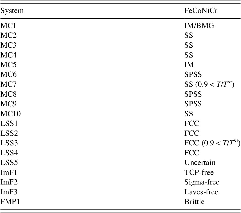
The CrFeCoNi alloy was chosen because it meets all the requirements outlined in Table I. Table II lists the results of all criteria determined by the HEAPS software. A detailed description of each criterion can be found in our group’s work (Martin et al., Reference Martin, Salvo, Pio and Aguilar2021). Based on the majority of the HEAPS criteria, a complete SS microstructure was predicted. Most of the MC criteria, which categorizes microstructures as SPSS, SS, or IM phases), predicted the presence of SS, single-phase disordered solid solution (SPSS), and SS, while only the MC criteria predicted the presence of IM or bulk metallic glass phases. On the other hand, the majority of the LSS criteria suggested an FCC crystal structure for the SS. The ImF criteria predicted the absence of topologically close-packed phases, such as Laves, μ, and σ phases (Dong et al., Reference Dong, Lu, Jiang, Wang and Li2014). It is important to note that all these criteria were primarily based on microstructural data of HEAs produced using casting methods, typically followed by annealing processes.
The criteria result of the HEAPS software.

BMG, bulk metallic glass; FCC, face-centered cubic; FMP, functional and mechanical property; HEAPS, High-Entropy Alloys Predicting Software; IM, intermetallic; ImF, intermetallic formation; LSS, lattice structure solid solution; SPSS, single-phase solid solution; SS, solid solution; TCP, topologically close-packed phase; Tm, melting point.
B. Characterization of HEA powder and cold-sprayed samples
HEA powder: Figure 1a presents the particle size distribution as a function of particle diameter, expressed in volume percentage. The distribution features a sharp peak centered at a mean particle diameter of 26 μm, with a median diameter (d₅₀) of 33.2 μm, indicating a slight skew toward larger particle sizes. Key statistical parameters include (i) standard deviation of 2.3 μm, reflecting a narrow size distribution; (ii) d₁₀ of 10.8 μm, representing the diameter below which 10% of the particles fall; and (iii) d₉₀ of 49.1 μm, indicating that 90% of the particles have a diameter below this value. Figure 1b presents the corresponding SEM image of the particles, revealing predominantly spherical shapes with smooth surfaces. The particles exhibit high sphericity with minimal irregularities, consistent with the unimodal and narrow size distribution observed in Figure 1a. These characteristics indicate a well-controlled production process, which is crucial for meeting the stringent requirements of cold-spray applications. Both particle size distribution and morphology play a key role in determining material behavior during the cold-spray process, affecting deposition efficiency, coating density, and adhesion to the substrate (Vaz et al., Reference Vaz, Silvello, Sanchez, Albaladejo and García-Cano2021). The spherical particle morphology observed in the SEM image provides several advantages for cold-spray applications. The main benefits of HEA spherical particles include (i) improved flowability (Vaz et al., Reference Vaz, Silvello, Sanchez, Albaladejo and García-Cano2021), because spherical particles, as shown in Figure 1b, exhibit reduced interparticle friction, leading to better flow characteristics compared with irregularly shaped particles. This enhances powder feeding consistency and deposition uniformity. This ensures consistent feeding into the spray nozzle, (i) minimizing clogging, and optimizing the spray process efficiency, (ii) higher deposition efficiency results from the uniform particle size distribution (Figure 1a), which ensures predictable particle velocities and impact energies during the cold-spray process, leading to better adhesion and coating uniformity (C. Zhang et al., Reference Zhang, Molla, Brandl, Watts, McCully, Tang and Schaffer2025). This minimizes the occurrence of suboptimal adhesion caused by over- or under-accelerated particles, thereby enhancing deposition efficiency and coating integrity, (iii) the controlled particle size (mean diameter of ~26 μm) falls within the optimal range for cold spray, ensuring that particles attain sufficient momentum to plastically deform upon impact while maintaining high velocity, which enhances coating adhesion and density, (iv) superior impact behavior is achieved because spherical particles ensure uniform impact stresses upon collision with the steel substrate, reducing stress concentrations and promoting better mechanical interlocking. This promotes efficient plastic deformation, essential for forming dense, high-strength coatings.
Characterization of high-entropy alloy particles: (a) particle distribution as a function of particle diameter, (b) scanning electron microscopy (SEM) image of particle size, and (c) SEM-EDS analysis of the powder.

For the sake of accuracy, the performance of a coating obtained by depositing spherical or quasi-spherical particles, that is, those produced via gas atomization, is not always superior to that of coatings formed from water-atomized particles, which have an irregular shape. The deposition efficiency, adhesion strength, and final properties of the coating depend on multiple factors, including particle deformability, surface roughness, and mechanical interlocking, which may sometimes favor irregularly shaped particles. It was demonstrated that irregularly shaped 316L particles can be deposited with the same deposition efficiency as quasi-spherical particles, while also ensuring higher adhesion strength between the coating and the substrate (Vaz et al., Reference Vaz, Silvello, Sanchez, Albaladejo and García-Cano2021). Therefore, it can be concluded that there is no inherently superior particle shape for deposition via the cold-spray process; rather, the optimal morphology depends on the specific material, process parameters, and desired coating properties. Therefore, the choice must always consider the specific properties and performance enhancements being targeted. Furthermore, the aforementioned study shows that the coating obtained from irregular particles exhibits better corrosion resistance than that produced using gas-atomized particles. However, despite its improved corrosion resistance, this coating does not show inferior wear resistance compared to the one obtained with regular-shaped particles. This highlights the importance of evaluating multiple factors beyond particle morphology when optimizing cold-spray coatings.
The elemental composition of the HEA was verified by SEM-EDS (Figure 1c). No additional alloying elements were detected above the EDS detection limit. A carbon signal is attributable to the carbon sticker for depositing the powders in the holder. These results confirm that the HEA alloy was near-equimolar according to the detection limits of the EDS.
Cold-sprayed sample: Figure 2 shows the HEA coating applied via cold spray on a carbon steel substrate. The coating appears relatively dense and homogeneous, with a smooth surface indicative of a well-executed deposition process. This aligns with the typical characteristics of cold spray, where high-velocity impact causes particles to plastically deform and adhere to the substrate (Tria et al., Reference Tria, Elkedim, Hamzaoui, Guo, Bernard, Millot and Rapaud2011). Overall, the uniform coating thickness demonstrates consistent feedstock powder flow and stable process parameters during cold spraying. Another characteristic that emerges from the cross section of the deposited coating is the absence of oxidation, which is inherent to the cold-spray process. As previously discussed in detail, the underlying mechanism of starting powder deposition in cold spray is the plastic deformation that occurs upon impact with the substrate, rather than particle melting, as in other thermal spray processes. This allows the deposited coatings to retain the same mechanical, physical, and chemical properties as the starting feedstock powders.
Scanning electron microscopy image of the substrate coating.

C. X-ray diffraction profile analysis
Figure 3 shows the XRD patterns of the HEA powder and the cold-sprayed sample or coating and the Rietveld plots for both simples. The XRD pattern of HEA powder shows the presence of FCC crystal structure only. The reflections indexed were (111), (200), (220), (311), and (222), and the space group correspond to
 $ Fm\overline{3}m $
(225). The XRD pattern of the HEA powder exhibited sharp, narrow peaks with small broadening, indicating low levels of microstrain and large crystallite size. This agrees with the synthesis method for the HEA powder. The atomization method produces metal and alloy powders from liquid state. During atomization, the molten metal is broken into fine droplets and rapidly cooled in a controlled atmosphere, typically by gas or water (German, Reference German2005). This cooling method reduces the formation of significant crystalline defects and residual stresses, which typically arise from high melting or mechanical deformation (Mandal et al., Reference Mandal, Sadeghianjahromi and Wang2022). Furthermore, the uniform heat dissipation during the atomization process allows for the growth of larger crystallites. On other hand, the XRD pattern of the cold-sprayed sample exhibits broadened diffraction peaks and decreased peak intensities compared to HEA powder. This broadening is attributed to the high crystalline defect density such as dislocations and crystalline size (or grain) refinement caused by intense plastic strain during cold-spray process. The crystalline defect density increment produces a microstrain increase (Aguilar et al., Reference Aguilar, Ordoñez, Guzman and Rojas2010; Hernández et al., Reference Hernández, Aguilar and Medina2019). Additionally, the plastic deformation process may induce texture changes, altering the relative intensities of specific peaks depending on the deformation mechanism and material structure (S. Zhang et al., Reference Zhang, Zhou, Zhou, Hu, Yershov and Wu2023). Figure 4 shows a comparison of normalized XRD patterns between the (111) and (222) planes of HEA powder and cold-sprayed coating. The peaks of cold-sprayed coating were considerably broadened compared to peaks of the HEA powders, highlighting significant microstructural changes induced by the cold-spray process.
X-ray diffraction patterns and Rietveld plot of (a) raw powder and (b) cold-sprayed coating.

Comparison between normalized (111) and (222) peaks of high-entropy alloy powder and cold-spray coating.

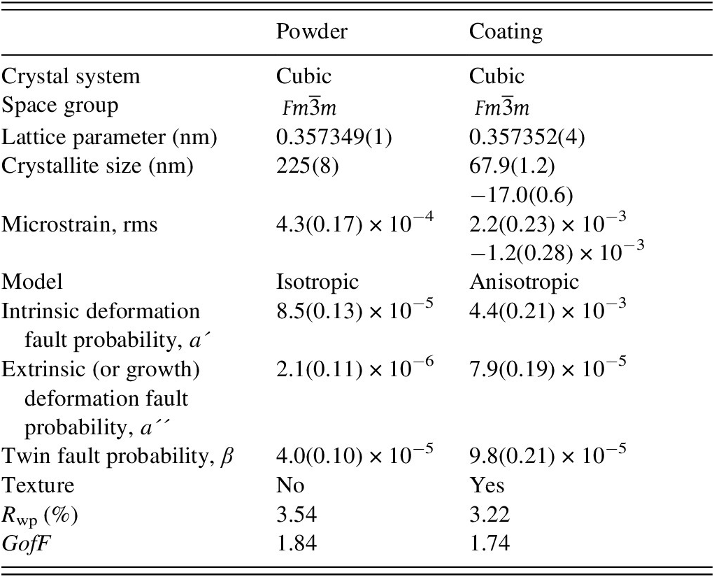
The main results computed by the Rietveld refinement are listed in Table III. The main difference between models used were as follows: (i) for the HEA powder, the Delf line broadening, size–strain isotropic model, and no texture were used, and (ii) for the cold-sprayed sample, the Popa LB line broadening, size–strain anisotropic model, texture, and Warren planar defects were used. The anisotropic model computed two crystallite size dimensions and two microstrain values. A negative crystallite size value indicates a concave surface, whereas a positive value corresponds to a convex surface. For microstrain, negative values represent compressive strain, whereas positive values indicate tensile strain. The refinement quality, indicated by the slightly lower R wp (3.22) and GofF (1.74) values for the cold-sprayed sample compared with the HEA powder (R wp: 3.54; GofF: 1.84). These figures of merit support the accuracy of the Rietveld method in characterizing the microstructure of both samples. A reduction in crystallite size was observed, decreasing from 225(8) nm in the HEA powder to 67.9(1.2) nm in the cold-sprayed sample, which highlights the role of grain refinement driven by dynamic recrystallization under the intense deformation conditions of cold spray (Tria et al., Reference Tria, Elkedim, Hamzaoui, Guo, Bernard, Millot and Rapaud2011). The microstrain value increased markedly from 4.3(0.17) × 10−4 in the HEA powder to 2.2(0.23) × 10−3 in the cold-sprayed sample, reflecting the generation of a high density of crystalline defects. The microstrain is produced by the introduction of crystalline defects such as dislocations, vacancies, and stacking faults within the crystallites (de Martínez et al., Reference de Martínez, Aguilar, Marín, Ordoñez and Castro2007; Aguilar et al., Reference Aguilar, Araya, Klein, Cardoso-Gil and Vargas2017; Salvo et al., Reference Salvo, Aguilar, Guzmán, Alfonso and Mangalaraja2019). A texture for the cold-sprayed sample was observed mainly in the {200} reflection. The lattice parameter exhibited a slight increase from 0.357349(1) nm in the HEA powder to 0.357352(4) nm in the cold-sprayed sample, indicating the presence of residual strain induced by the high strain rates and impact forces experienced during particle projection (Özbilen et al., Reference Özbilen, Vasquez, Abbott, Yin, Morris and Lupoi2023). The planar defect values showed differences between the two samples. The following planar defects were computed: (i) intrinsic stacking (deformation) fault, αʹ, (ii) extrinsic stacking (growth or deformation) fault, αʹʹ, and (iii) twin fault, β. The HEA powder sample exhibited smaller planar defects than those of the cold-sprayed sample. The αʹʹ value in the HEA powder 2.1(0.11) × 10−6 was one order of magnitude smaller than the cold-sprayed coating 7.9(0.19) × 10−5. The αʹ value in the cold-sprayed coating 4.4(0.21) × 10−3 is two orders of magnitude larger than the HEA powder 8.5(0.13) × 10−5. The αʹ is the intrinsic deformation fault that is produced when metals and alloys are subjected to plastic deformation. The β value 4.0(0.10) × 10−5 for the HEA powder is half that of the cold-sprayed coating, 9.8(0.21) × 10−5. The results were in agreement with the cold-spray process because it produces plastic deformation (Ghelichi et al., Reference Ghelichi, Bagherifard, Mac Donald, Brochu, Jahed, Jodoin and Guagliano2014; Chen et al., Reference Chen, Liu, Chu, Zhang and Zheng2022). Intrinsic and extrinsic stacking faults in FCC metals and alloys are considered similar (Hirth, Reference Hirth1982). Extrinsic stacking faults are not often observed in practice, so stacking faults in FCC metals and alloys is usually assumed to be intrinsic (De Cooman et al., Reference De Cooman, Estrin and Kim2018). This is the reason why the extrinsic stacking fault values are small.
Microstructural parameters obtained by Rietveld refinements using the MAUD software.

MAUD, Materials Analysis Using Diffraction.
The HEA powder displayed an isotropic microstructure, whereas the cold-sprayed sample exhibited anisotropy, suggesting the development of texture due to the unidirectional impact and compression forces associated with the deposition process (Bagheri et al., Reference Bagheri, Pariente, Ghelichi, Guagliano and Vezzú2010). The plastic deformation experienced during particle deposition not only caused lattice distortions but also facilitated interparticle bonding and strong adhesion to the substrate. These microstructural changes, induced by the cold-spray process, are expected to enhance the mechanical properties of the coating, including improved strength through grain boundary and dislocation strengthening mechanisms. However, the increased microstrain and texture may introduce residual stresses, which could influence the adhesion and durability of the coating. These results demonstrate the significant impact of the severe plastic deformation inherent to the cold-spray process on the microstructure of HEAs, providing insights into tailoring coating performance for advanced applications. These changes in XRD patterns provide valuable insights into the microstructural evolution of the HEA powder and cold-sprayed samples.
Recent studies on cost-effective Fe-based HEAs subjected to severe plastic deformation have confirmed that microstructure refinement is a key pathway to enhance hardness and wear resistance. For example, cyclic closed-die forging was shown to produce ultrafine grains (≈100–300 nm) and significantly increase hardness and tribological performance in Fe–Mn–Co–Cr–Ni–Cu alloys (Naseri et al., Reference Naseri, Myasnikova, Imantalab, Gholami, Mikhailov, Amra and Shaburova2024b), Fe–Ni–Cr–Mo–Al systems (Naseri et al., Reference Naseri, Myasnikova, Gholami, Imantalab, Mikhailov, Amra and Shaburova2024a), and Fe–Ni–Cr–Mo–Al variants (Naseri et al., Reference Naseri, Myasnikova, Imantalab, Gholami, Mikhailov, Amra and Shaburova2024c). These reports demonstrate that deformation-induced lattice defects and texture development (e.g., Rotated Cube {001}<110> component) play a central role in improving wear resistance. The present findings on CrFeCoNi coatings deposited by cold spray are consistent with these observations, as Rietveld refinement revealed peak broadening and increased microstrain, indicating microstructural refinement similar to that observed in SPD-processed HEAs. This supports the interpretation that cold spray, through its high-velocity impact and associated plastic deformation, can act as an alternative pathway to achieve refined and defect-rich microstructures in HEA coatings, thereby contributing to their mechanical performance.
Figure 5 depicts the crystallite shape of the cold-sprayed coating in a three-dimensional representation, which was computed using MAUD software and Popa’s anisotropic model (Popa, Reference Popa1998). The crystallite shape is anisotropic, resembling an ellipsoid or distorted sphere, as indicated by the differing radii of 67.9(1.2) (convex surface) and −17.0(0.6) nm (concave surface). The positive radius along one axis reflects an elongated or stretched crystallite dimension, whereas the negative radius of −17.0(0.6) nm suggests compressive strain or distortion, likely resulting from the severe plastic deformation inherent to the cold-spray process. This anisotropic crystallite morphology aligns with the intense mechanical impact and strain experienced by the particles during cold-spray deposition, where high-velocity impacts lead to grain refinement, dislocation density increases, and deformation-induced defects. The resulting microstructure typically exhibits preferred orientations or texture, contributing to the observed anisotropy in crystallite shape.
Modeling of anisotropic crystallite shape of the cold-sprayed coating.

IV. CONCLUSION
The Rietveld refinements provided a comprehensive microstructure characterization of the HEA powders and coatings. The results of lattice parameter, crystallite size, microstrain, planar defects, and texture give critical insights into the interplay between processing conditions and microstructure. Upon cold-spray deposition, the HEA coatings underwent substantial microstructural evolution, which leads to the following conclusions:
-
• Phase stability both the gas-atomized feedstock and the cold-sprayed coating remain single-phase FCC, and the lattice parameter is essentially unchanged (powder a = 0.357349(1) nm, coating a = 0.357352(4) nm), indicating no phase transformation during deposition.
-
• Size–strain refinement: Cold spray induces severe plastic deformation that reduces the crystallite size from 225(8) nm (powder) to 67.9(1.2) nm (coating) and increases microstrain from 4.3(0.17) × 10−4 to 2.2(0.23) × 10−3. The coating shows anisotropic size–strain consistent with impact-driven directional refinement.
-
• Defects and texture: The coating exhibits enhanced {200} preferred orientation and markedly higher planar-fault probabilities, especially intrinsic stacking faults (α′ ≈ 4.4(0.21) × 10−3 vs. 8.5(0.13) × 10−5 in powder), consistent with deformation-controlled faulting and twinning observed in FCC alloys.
-
• Process–structure link: Full-pattern Rietveld/MAUD analysis (anisotropic size/strain, texture, and stacking faults) provides quantitative microstructural descriptors that capture cold-spray-induced refinement and defect formation, offering actionable targets for process optimization and anticipating improvements in mechanical/tribological performance.
FUNDING STATEMENT
C.A. acknowledges financial support from the Millennium Institute on Green Ammonia as Energy Vector – MIGA (ICN2021_023), funded by the Millennium Scientific Initiative, FONDECYT No. 1230620, FONDEQUIP No. EQM140095, and Postgraduate No. 74220021 from the Agencia Nacional de Investigación y Desarrollo (ANID). A.S. acknowledges support from Grant PID 2021-128917NA-I00, funded by MICIU/AEI/10.13039/501100011033 (Spain) and, as appropriate, by “ERDF A way of making Europe,” by “ERDF/EU,” by the “European Union” or by the “European Union NextGenerationEU/PRTR. I.G.-C. acknowledges support from Generalitat de Cataluña (Grant No. 2021SGR00712).
COMPETING INTERESTS
The authors have no competing interests.