Introduction
Volumetric modulated arc treatment (VMAT) delivered treatment faster than multiple static fields of intensity-modulated radiotherapy (IMRT) without compromising the dosimetric goal. Reference Munshi, Sarkar, Roy, Ganesh and Mohanti1 So, in several treatment regions, VMAT has become the standard of care and the technique of choice for external beam radiotherapy. Reference Sarkar, Manikandan, Nandy, Munshi, Sayan and Sujatha2 Head and neck cancer was one treatment region where VMAT performed better than IMRT dosimetrically and in delivery time. Reference Broggi, Perna and Bonsignore3 Due to clinical requirements, planning target volume (PTV) may be very much proximal to the critical organ at risk. A high dose gradient concerning distance would be created in such a case during treatment planning for VMAT. With a high gradient in the distribution, VMAT demands a proper setup through image guidance to avoid missing any clinical or subclinical disease, leading to locoregional failure. Reference Teoh, Clark, Wood, Whitaker and Nisbet4 Although there were limited solutions for image guidance, like two-dimensional portal imaging, stereoscopic imaging and surface guidance, the most accurate and the standard was the linear accelerator embedded in cone beam CT. Reference van Herk5,Reference Cao, Liu and Zhai6 Quite a few articles showed the high accuracy of cone beam computed tomography (CBCT) and compatibility with other imaging systems.
There were various methods available for registration of cone beam CT to planning CT. Reference Teoh, Clark, Wood, Whitaker and Nisbet4,Reference Goldsworthy, Leslie-Dakers and Higgins7,Reference Mohandass, Khanna and Kumar8 The choice available to the user depended on the make and model of the equipment and the licences available for the equipment. Users must evaluate the benefits and drawbacks of each technique and establish an institution-specific protocol for patient setup image registration. The available image registration methods using CBCT and treatment planning system (TPS)-generated images for X-ray volumetric imaging (XVI) were as follows. There were clip box registration (CBR), mask-based registration, and dual registration (DR). Reference Goldsworthy, Leslie-Dakers and Higgins7,Reference Mohandass, Khanna and Kumar8
-
(1) CBR: In this method, an region of interest (ROI) was defined on the CT image in the form of a box drawn on any of the three orthogonal views around the ROI.
-
(2) Mask registration (MR): This used image registration using a particular soft tissue (ST) volume. The mask sets an irregular volume of interest around the main chosen volume. The registration was restricted to the voxels inside this volume and should include the target.
-
(3) DR: DR was defined as the combination of CBR & MR. The average of these errors, determined from these registrations, was attributed to the final patient setup error.
Users can use the three registration methods for patient setup verification per the requirements. In our institute, the XVI (version 4.5.1) enabled manual matching and clip box-based automatic matching. For automatic matching, the options available were bone matching or grey value-based (ST matching). Cao et al. compared image registration methodology with different ROIs in lung cancer radiotherapy. Reference Cao, Liu and Zhai6 It was found that the automatic image matching of onboard imaging (OBI, Varian, Palo, Alto, CA) was accurate and highly reliable for detecting offset errors.
The appropriate choice of the registration between the cone beam CT and reference image depended upon the ROI. Bone matching was considered appropriate in parts covered by a bony structure or the area where target volume was determined by a bony landmark (like the spinal cord). According to Cambel et al., ST matching was considered the gold standard. Reference Campbell, Owen, Brown, Pryor, Bernard and Lehman9 This study compared the efficacy of bony matching with ST matching. Also, the image registration time for bony landmark (BL) and ST matching for the head-neck site were compared. Relevant publications mentioning the benefit and limitations of bony matching in head-neck sites compared to ST matching were not found.
The final quantitative outcome of the setup verification data was to determine the setup margin (SM). The PTV was defined by a safety margin over the clinical target volume (CTV) to be vigilant of the positional error due to random and systematic shifts of the latter. The van Hark formula was the most common technique for calculating a margin over a population of patients having multiple treatment sessions. Multiple investigators justified and validated this formulation for different treatment sites and used it in all modern clinical practices. Reference Gill, Reddy, Campbell, Chen and Pearson10,Reference Dionisi, Palazzi and Bracco11 Therefore, determination of the SM was essential to accurately delivering treatment.
This article evaluated the characteristic change in the SM as a function of the two different image registration methods for the head and neck regions receiving treatment using the VMAT delivery technique.
Novelty: During SM calculation, much literature did not consider the type of registration used for matching. However, shift values differ based on the registration process during image matching, which may result in different PTV margins for other registration processes during portal imaging. Here we have tried to find the correlation of the CBCT matching process with setup error in head-neck cancer patients. We have not found any suitable publication for margin compared with the matching methods. It was found that less time was required for bony matching compared to ST matching, maintaining same quality which was also a new finding.
Materials and Methods
Radiotherapy treatment planning and patient selection
Simulation contouring and treatment planning
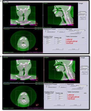
All patients were simulated in head-first supine condition with both arms by the side using a five-clamp head and neck thermoplastic mask. Using the CT room’s laser (DORADO, LAP GmbH, Germany), three fiducial markers were placed on the patient’s anterior and lateral places during CT scan simulation. 3mm CT slices were obtained encompassing the region 2 cm above the orbit and lower level up to carina bifurcation as a standard CT simulation approach for all head-neck patients. Despite having a poitron emission tomography (PET)/CT machine, CT was taken as primary image data for all patients. PET data were acquired for some patients based on recommendations by the clinician. CT scans were used to outline all patients’ tumours. Figure 1(a) and (b) showed the typical CBCT matching window in XVI. Thirty head and neck cancer patients received a simultaneous integrated boost of 54-60-66 Gy in 30 fractions. 6MV flatten beam was used for VMAT planning. Patients received daily CBCT scans throughout therapy. When shifts above the action level were established by our hospital protocol, that is, 3 mm for translational direction, and 3 °for rotational direction, inter-fractional images were collected. If positional error exceeded the action level, another CBCT was acquired after correcting the table position. Reference Sarkar, Ganesh and Munshi12 Same action protocol applied for repeated imaging. Although 900 CBCT images were taken during setup, 33 could not be retrieved, making this image CBCT 867 with 1734 registrations. Several radiation therapists registered images at separate times. Radiation therapists requested that the on-call radiation oncologist and medical physicist examine the imaging and make a determination regarding the use of shift if shift data exceeded the 3 mm, 3° action threshold during registration. Inter-operator variability cannot, therefore, be ignored in this study. All study patients’ VMAT treatment plans were created using Monaco TPS (V5·11·1, IMPAC Medical System, Inc., MU). After radiation oncologist approval, the planned CT dataset and treatment coordinates were transferred to the XVI console.
(a) and 1 (b) depicted two XVI image registration procedure for head and neck patients.

CBCT image acquisition procedure
In image-guided radiotherapy treatment (IGRT), XVI system with an Elekta Synergy® (Elekta Ltd, Crawley, UK) LINAC was utilised to acquire CBCT pictures after positioning the patient using TPS shift coordinates. Before treatment, image verification system checked the patient’s position. Elekta Synergy® (Elekta Ltd, Crawley, UK) had a kilovolt X-ray source arm and a flat-panel detector. The linac was equipped with EPID IviewGT Elekta, based on the aSi panel XRD 1640 AL5 (PerkinElmer Optoelectronics, Fremont, CA USA). With a pixel pitch of 400 m, the active area of the sensitive layer was 409·6x 409·6 mm2. Elekta’s scanning technology was used to obtain three-dimensional CBCT (3D-CBCT) images. Image collection parameters were 120 kV, 528 mA, clockwise or counter-clockwise gantry rotation from 180° to 180°, 1 rotation per minute gantry speed, collimator cassette M20, F1 filter and 330 frames. Using XVI software, 0·2 cm CBCT images were collected and reconstructed. XVI employed Feldkamp–Davis–Kress algorithm to match CT and CBCT. Reference Schäfer, Borgert, Rasche and Grass13 XVI’s user guideline suggested verifying matching precision on a phantom. 14
CBCT image matching procedure
Monaco (V5·11·1, IMPAC Medical System, Inc., MU) TPS used 3D image series to calculate the patient’s setup deviance. Feldkamp’s back-projection algorithm was used to create 3D datasets from 2D image data. Reference Schäfer, Borgert, Rasche and Grass13 XVI could be used for automatically or manually matching patient’s images. Automatic matching was possible using either bone landmarks (BL) or ST. Bony landmark available in the PTV adjacent area was considered for bony matching. The most prevalent markers were C1–2, C5–7, occiput and mandible. Grey value-based matching (ST matching) was time-consuming compared to bony matching. For ST matching, the time required for a head-neck case was 28·6 ± 7·5 s. Bony landmark-based image registration took 1s for all head-neck patients under study. As per Meyer et al., ST matching was considered superior to bone matching. Reference Meyer, Wilbert and Baier15
Grey value (translational(T)+ rotational(R)) matching
In this work, patient treatment setup errors were analysed using ST (T + R) automatic image matching procedure. Maximum translational and rotational error tolerances were 3 mm and 3°. As the linac did not have a 6D couch, the couch under study could not correct rotational inaccuracies. Inaccuracies higher than 3° required repositioning and a second CBCT. Sarkar et al. published a rotational correction action procedure that could be further utilised for a non-6D couch system. Reference Sarkar, Ganesh and Munshi12
CBR matching: The image’s area of interest was boxed in sagittal, coronal, and axial views. User-specified box dimensions were available. Each image set only evaluated voxels within the target’s clip box. A rigorous registration technique did not account for image margins. Chamfer matching was a powerful tool for shape-based detection in cluttered images. Reference Yu, Wei and Yang16
Patient setup errors
The patient setup error was defined as the difference between the actual and predicted position of the treated region of the body. The planned position and the image data from the TPS via the Digital Image and Communication in Medicine export process were sent to the imaging console. Image sent from TPS was considered as a baseline for the patient.
Setup errors were classified into two types: systematic errors and random errors.
Systematic error (∑): Systematic error was considered a deviation from the planned patient position to the average position for fractionated radiation therapy. The systematic error for a population of patients was determined using the standard deviation of mean errors for each patient using two distinct registration methods. Reference van Herk5,Reference Czajkowski and Piotrowski17
Random error (σ): Random error was a variation between fractions during the same patient’s treatment sequence. It was measured using two different registration methods as the root mean square value of the standard deviation of errors acquired for each patient. Reference Czajkowski and Piotrowski17,Reference Palombarini, Mengoli, Fantazzini, Cadioli, Degli Esposti and Frezza18
Analysis of mean setup errors in three translational directions using two methods
Mean displacement vector (R)
The mean displacement vector had a length equal to the shortest distance between the point’s initial and final positions. It was expressed in terms of the patient’s overall setup error distance, considering three translational coordinates, where, correspondingly, dx, dy and dz were deviations in the x, y, and z directions, and r was the mean displacement.
Margin calculation
Margin calculation was done with the van Herk formula Reference van Herk5 ; for any translational direction as
Margin = 2.5Σ + 0.7σ
where Σ was the systematic error and σ was the random error in any particular direction for any particular site.
Statistical analysis
The statistical analysis was performed on two different registration methods using the Pearson correlation test (P < 0·05) to determine the P value of the analysed data using SPSS software (SPSS V.16, IBM, IL, USA). Bland–Altman analysis was performed using Microsoft Excel 2019.
Results
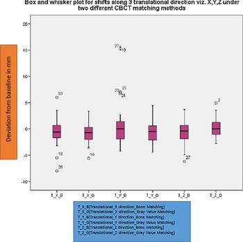
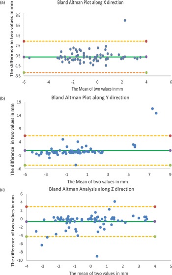
The final results showed similarities and contrasts in setup errors due to the influence of two different CBCT registration techniques. Variation of shifts in different directions under two different registration is shown in Figure 2 by using a box and whisker plot. It could be inferred from the plot that the deviation was within 2 mm in most instances. Bland–Altman plots were used to compare two different methodologies’ efficacy. Bland–Altman plots identify systematic differences (fixed bias) or outliers. Bland–Altman plot (difference plot) compared two arrays. It could also be used to reach a new measurement technique or method with a gold standard, as even a gold standard was not error-free. The shift data obtained from two methodologies were analysed using Bland–Altman analysis for three translational directions, as shown in Figure 3(a)–(c). Figure 3(a)–(c) illustrated that the two methodologies were comparable, and the difference was insignificant.
Translational shifts along three directions with two different registration methods by box and whisker plot.

(a). Translational shifts along X direction with two different registration methods. (b). Translational shifts along Y direction with two different registration methods. (c). Translational shifts along Z direction with two different registration methods.

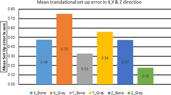
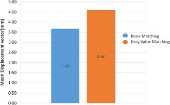
The mean setup errors for BL and ST matching in the X direction (0·48 mm, 0·75 mm), in the Y direction (0·33 mm, 0·56 mm) and in the Z directions (0·47 mm, 0·17 mm) were observed, as shown in Figure 4. For grey value matching (ST matching), the time required for a head-neck case was 28·6 ± 7·5 s. BL took 1s for all head-neck patients with same area of interest. As shown in Figure 5, the value of the mean displacement vector was lower in BL method (3·68 mm) than in ST method (4·6 mm). There was no statistical significance of one method over another (P > 0·05). For BL and ST, the systematic error contribution along 3 translational directions was X direction (0·6, 0·54), Y direction (2·02,1·92) and Z direction (1·3,1·15), respectively. The random error contribution for BL and ST were the X direction (1·4, 1·28), Y direction (1·35, 1·33) and Z direction (1·41, 1·33), respectively, along with three translational directions. This was shown in Table 1. The values for total systematic error (∑) and total random error (σ) for different translational directions with different matching methodologies are shown in Table 2.
Comparison of mean setup error in two different registration methods.

Comparison of mean displacement vector for bone and grey value matching.

Calculation for systematic and random part from CBCT-acquired data for two different registration methods

∑ and σ calculation for two different registration methods

The margin calculated based on different registration methodology was as follows; X margin (BL) = 4·6 mm, X margin (ST) = 4·4 mm, Y margin (BL) = 6·2 mm, Y margin (ST) = 4·7 mm, Z margin (BL) = 3·0 mm, Z margin (ST) = 3·6 mm.
Discussion
Accurate patient positioning was crucial for clinical success. Accurate patient placement reduced CTV-to-PTV margins. Reducing the CTV-to-PTV margin allowed target volume dose escalation, which may improve tumour control and prevent normal tissue complication rate. CBCT could be used to measure and correct patient setup errors, improving RT efficacy and accuracy. IGRT reduced patient setup errors, according to various studies. Reference Hawkins, Aitken, Hansen, McNair and Tait19,Reference Guckenberger, Roesch, Baier, Sweeney and Flentje20
Because complex treatment options like VMAT and IMRT produce a more conformal and steep dose distribution, IMRT and VMAT require precise patient positioning. Patient placement was vital for improving target localisation efficacy and reducing morbidity in crucial organs. Many factors contribute to uncertainty in the placement of the PTV. The van Herk formula used CBCT image shift measurements to calculate the PTV margin. Reference Cao, Liu and Zhai6 In head-neck VMAT treatment, there were very few published literatures comparing BL and ST matching with respect to possible impact in PTV margin. The current study analysed translational errors in setup adjustments utilising CBCT images in head-neck cancer treatment using VMAT and two registration approaches.
Hawkins et al. tested the CBR approach on oesophageal cancer patients. Reference Guckenberger, Roesch, Baier, Sweeney and Flentje20 Their study analysed 122 EPID image pairs and 207 CBCT images. Reference Hawkins, Aitken, Hansen, McNair and Tait19 According to Hawkins et al., clip box orientation and registration methods can affect displacements (translation and rotation). The clip box area could fluctuate in clinical applications based on clinical site and volume.
Guckenberger et al. studied the influence of clip box size on head and neck cancer patient setup errors using 98 CBCT pictures. Reference Guckenberger, Roesch, Baier, Sweeney and Flentje20 Guckenberger et al. recommended limiting clip box size to the ROI, including the patient’s skull. In VMAT breast cases, all registration methods exhibited an insignificant difference in patient setup error. Reference Mohandass, Khanna and Kumar8 According to Mohandas et al., Reference Mohandass, Khanna and Kumar8 automatic CBR matching ensured easy target position verification. The insignificant difference in bony and ST matching for head-neck patients provided similar inference as Mohandas et al. for breast patients. Goldsworthy et al. compared clip box and DR to treat oropharyngeal carcinoma. Reference Goldsworthy, Leslie-Dakers and Higgins7 The results of this study demonstrated that there was a clinical difference between using a standard CBR and DR in patients with oropharyngeal cancer. Our results showed an insignificant difference between ST and bony matching.
The lack of statistical difference does not mean there is no significant difference but that the method and data cannot demonstrate a difference statistically. Hence, an alternative approach, viz. Bland–Altman analysis, was chosen to analyse the data further. The Bland–Altman analysis results are shown in Figure 3(a)–(c). In Figure 3(a)–(c), it was clearly seen that most of the data were within the upper line of agreement (LOA) and lower LOA for all their translational direction. It implied all three dataset’s mean values of two different methodologies have a similar outcome or are comparable. A similar inference was obtained from the Pearson correlation test. The result from the Bland–Altman analysis inferred the same conclusion as the other methodology. The two registration techniques revealed no statistically significant differences in the systematic error component, random error component, mean displacement vector, or mean setup error. In this study, bone matching was faster than grey value matching.
Interobserver variability during image registration, patient motion during image acquisition and severe reduction in image quality due to the presence of dental prosthesis were the limitations of our study. No intrafraction images were taken into consideration in this study.
Radiotherapy departments may have the additional benefit of faster registration time with the bone registration method compared to a ST registration method. Reduced time reclining on the treatment couch relieved a patient with a tight thermoplastic mask on the face. Reducing treatment duration could reduce couch wait times and setup errors. Bony matching sped up the process of image matching for head and neck patients without sacrificing accuracy in registration. It was an addition that may be deployed routinely to provide faster treatment while keeping the same quality of care.
Conclusion
The different registration processes provided different perspectives on image registration. Shift results ended up maintaining an action protocol for shift management. Hence, it was essential to quantitatively assess other registration processes while using them in our department. The SM difference obtained during this assessment could be incorporated while delineating the PTV for any particular site. In this study, two different registration methods for head-neck cancer patients were evaluated quantitatively. PTV margin was calculated based on van Herk formulae. Mean translational setup error and mean displacement vector for two registration methods were also compared in this study. The two registration methods, namely bone matching and ST matching, did not show any statistically significant difference in their ability to detect patient positioning errors in X, Y and Z directions for head-neck VMAT treatment delivery. For patient setup verification, the user can select either one of the two registration methods. Image registration in head-neck cases using bony matching was less time-consuming while maintaining the same registration quality. It was an excellent feature which could be regularly utilised to deliver a faster treatment maintaining the same quality of treatment. Dependence of registration method on the PTV margin for different sites can be calculated and compared. Hence, PTV margin calculation and efficacy of each registration method for brain, thorax and pelvic sites can be further evaluated. Thereafter, the relationship between PTV margin and registration methods can be understood in a more efficient manner.
Acknowledgements
We would like to thank Mr. Abhijt Pal, a medical physicist at AMRI Hospital Kolkata, for his assistance. Mr. Nilendu Saha, an Elekta service engineer, is also appreciated for responding to my inquiries on occasion. Dr. Arjunan Manikandan, Senior Medical Physicist at the Apolo Proton Cancer Centre, also deserves our gratitude.
Financial Support and Sponsorship
Nil.
Conflicts of Interest
There are no conflicts of interest.