Introduction
In the present scenario, reconfigurable antennas with multiple frequency bands for commercial applications are most convincing for transmitting and receiving different frequency applications. In the design of reconfigurable antennas, slot antennas are considered as building blocks, and these are considered for ultra high frequency [Reference Pozar1, Reference Peroulis, Sarabandi and Katehi2]. Reconfigurable patch antennas are additionally intended to work in both L and X-frequency bands [Reference Liu, Shi and Liu3, Reference Gupta, Joshi and Khanna4]. The tunability now and again makes the system an intelligent system. Generally, reconfigurability of an antenna is acquired by varying the frequency of operation, improving the radiation patterns. The reconfigurable antenna governs the resonating frequency of the antenna and assists to resonate at different frequency bands. Variable solutions are available for matching network; among them, impedance-matching network is the best possible solution used to estimate the characteristic impedance of the device [Reference Pozar5, Reference Garg, Bhartia, Bahl and Ittipiboon6].
At present, the radio frequency micro electro mechanical switches (RF-MEMS) technology is attractive for different applications such as military, satellite, and commercial applications. Though many of the RF-MEMS devices exist in the market, only switches are preferred due to numerous advantages such as lower power consumption, low insertion, and high isolation, and good reliability switches are preferred to reconfigure the frequency. The system performance can be increased by embedding the optimized switch on to the patch. To overcome the challenges of p-n diode and feild-effect transistor such as longer switching time and more power consumption, switches are preferred as basic building blocks [Reference Attaran and Rashidzadeh7–Reference Kolte and Mahajan11]. In satellite communication applications, to attain the switching between frequency bands, the reconfigurable antennas are required [Reference Cetiner, Jafarkhani, Qian, Yoo, Grau and De Flaviis12–Reference Mak, Rowell, Murch and Mak14]. There are many possibilities to estimate the achievement of the MEMS switch integrated with patch antennas, few of them are intended for in [Reference Hong, Kim, Park, Kahng and Choi15–Reference Brown17]. Impedance matching also needs to be verified while integrating the antenna with MEMS device. To overcome a few challenges in the traditional devices, these RF-MEMS devices are introduced to the patch antennas to enhance the switching probability. Here, switches are of two types namely series and shunt type. Depending on the configuration, shunt switches are preferred and they provide excellent performance. Switches are the basic building block of the RF signal functioning system, so they can be used on the patch to reduce the interference. Reconfigurable antennas support more than one wireless standard, reduce the cost and volume requirement, and provide narrowband or wideband operation.
In the design of reconfigurable antennas, slot antennas are considered to be essential components. As mentioned earlier, due to different positions of switch integration on these slot antennas [Reference Simons, Chun and Katehi18], it is feasible to alter the characteristics of the antenna. This is concluded by adjusting the electrical length of the current flow or control the flow of current distribution around the slot [Reference Badía, Nicole and Ionescu19–Reference Sharma, Tripathi and Rishi22]. By integrating the actuating circuits in the antenna system, the overall performance of the antenna can be increased. In this work, we incorporate a slot antenna into RF-MEMS to compose a novel antenna.
Most of the techniques are introduced to make use of radio spectrum with great performance; significance interest has been shown to the orbital angular momentum of light (OAM) antennas. A large amount of data is to be swapped with the help of OAM communication system for wireless servers. This process requires the transmitter and receiver to be aligned with one another. The channel capacity can be improved in a link between two antennas through different means. The aim is to notice that an antenna at once can create various fields. However, each field is associated with an alternate measure of orbital force [Reference Morabito, Di Donato and Isernia23].
In this work, the design of reconfigurable elliptical-shaped patch antenna is proposed with a single band for satellite application. The proposed elliptical-shaped patch resonates at the frequency from 10.3 to 10.6 GHz. The presented antenna structure is controlled by the design of the switch geometry. The radiation patterns and the return loss are presented. The proposed MEMS device is embedded into the elliptical antenna. The switching reconfiguration can be achieved by the proposed switch. The impedance-matching technique is verified through Smith chart and is performed for the proposed switch-based elliptical microstrip patch antenna. The proposed electrostatically actuated capacitive switch is of fixed-fixed type. The switch provides an excellent RF performance. The actuation voltage estimated for the proposed switch is very low. From the results, the proposed switch is considered for the elliptical-shaped antenna to be integrated. The proposed antenna integrated with the switch can be used for satellite applications. The prototype of the proposed antenna is fabricated and tested experimentally. The proposed antenna is suitable for satellite applications of low interference due to one resonant band.
The proposed antenna is considered with an elliptical shape and embedded split-ring resonator (SRR). The non-uniform meander line shunt capacitive RF-MEMS switch is proposed. RF-MEMS switch is integrated into elliptical-shaped microstrip patch antenna at SRR. The antenna performance is observed at three conditions. The detailed explanation is given in antenna design. The theme of the proposed antenna is resonated at a single band to reduce interference for satellite application. Such a type of design is not available in the literature as per our (authors’) knowledge. To validate the performance verification of the elliptical SRR antenna, the designed model is fabricated and tested.
This paper consists of four sections; section “Introduction” provides introduction. Section “Design description” describes the design of the proposed antenna and the shunt capacitive switch specifications and the working. Section “Results and simulations” consists of the results and discussions of the proposed work at different conditions of antenna embedded into the switch. Section “Conclusion” concludes the findings of the proposed work.
Design description
Elliptical antenna
The Fr-4 substrate material (ɛr is 4.4, h = 1.6 mm) is considered for designing the proposed antenna. The length and width of the substrate materials are L1 and W1, respectively. An elliptical-shaped patch antenna is metallized on the substrate material with a thickness of 0.01 mm. Full ground plane is quoted on the other side of the substrate. A circular-shaped complementary split ring resonator (CSRR) is etched from the elliptical-shaped patch antenna with inner and outer radii of r1 and r2 and a slit gap of 0.4 mm. The dimensions of the elliptical patch antenna are given in Table 1. The proposed antenna is embedded on the ring slot etched on the SRR, and finally, the switch is placed on the patch.
The optimized values of the proposed antenna

MEMS switch design
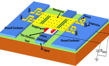
The device was modeled in the tool having one switch on CSRR slot in an elliptical patch. The characteristic impedance maintained for the device is 50 Ω. The present design consists of a dielectric with a thickness of 0.3 μm. The area of overlap between the electrodes is 110 μm × 100 μm that is used to validate the capacitance of the switch, which improves the isolation performance. Two sides of the device consist of non-uniform meander lines to reduce the spring force. The spring constant (k) is associated with the actuation voltage. Lower the spring constant, lower the actuation voltage. The material used for the membrane of the switch is gold as it has good conductivity. The dimensions of the switch are given in Table 2. The RF signal passes through the switch from input to output in ON state, while in OFF state, there is no transmission and the air gap exists from the signal line, and the co-planar waveguide line is 3 μm which is apt for fabrication (Figs 1–3).
Proposed antenna with RF-MEMS switch.

Top perspective of the proposed non-uniform meander switch.

One-dimensional view of the proposed switch.

The geometry specifications of the proposed device

Results and simulations
Electromagnetic performances of the antenna
The implementation evaluations that were achieved from this simulation are given as follows:
Reflection loss
Reflection loss is characterized as the measure of power loss caused by the reflection of power at a line interruption. It is communicated in terms of decibels (dB) and the return loss is conveyed in equation (1).

where τ is the reflection loss of the proposed antenna.
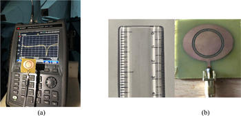
The return loss of the proposed elliptical-shaped patch antenna and the other two conditions sustained with MEMS switch ON and OFF state is shown in Fig. 4. The reconfigurability can be observed in the figure at different conditions of the switch. The proposed antenna exhibits maximum reflection loss at the antenna with switch in OFF state. The performance of the fabricated prototype is measured by a vector network analyzer in an anechoic chamber presented in Fig. 5. The comparison analysis of the proposed antenna's simulated and measured results is shown in Fig. 6.
Reflection loss of the proposed antenna with different states of the RF-MEMS switch.

(a) Fabricated antenna with vector network analyzer in an anechoic chamber. (b) Fabricated prototype of the proposed antenna design.

Simulated and measured results of the proposed antenna design.

Impedance matching
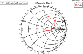
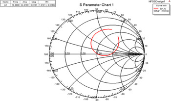
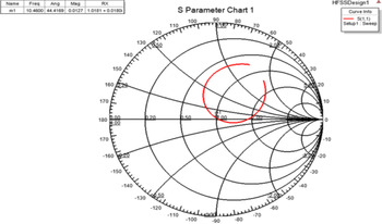
Impedance coordination is presented by employing a coordinating system with lumped components (LandC). Different feasible improvements are accessible for coordinating system design. They are mostly influenced by design complication, its execution, and flexibility. The ideal plan for matching network utilizing lumped components can be achieved by Smith chart. The ideal impedance of the antenna (Z L) is ought to be considered. Eventually, the ideal impedance for the switch can be validated as (Z 0). In order to meet the required assessment, the device geometry is to be made properly. To attain the proper matching, the antenna and the switch need to satisfy the condition (Z 0 = Z L). The lumped elements involve in matching the input impedance. Only when the proper matching is done, it can be verified with the Smith chart. Though many solutions are available, only Smith chart is selected among them. To verify the proper matching, the input impedance should meet the focal point of the Smith chart. If the input impedance is away from it, the condition mentioned above will not be satisfied. The impedance ought to be considered as 50 Ω.
From Figs 7–10, the characteristic impedance of the antenna, antenna with switch ON state, antenna with switch OFF state, and finally the proposed switch is observed. The investigation on impedance with and without RF-MEMS switch on elliptical patch antenna is studied. The switch may be in open or closed condition depending on the scattering parameters.
Impedance matching of the antenna in Smith chart showing an input impedance of 50 ohms.

Elliptical-shaped microstrip patch antenna with the proposed switch in ON-state impedance-matching network in Smith chart.

Elliptical-shaped microstrip patch antenna with the proposed switch in OFF-state impedance-matching network in Smith chart.

Impedance-matching network of the proposed switch in Smith chart.

The impedance of the elliptical patch antenna and the embedded switch is observed for two (ON and OFF) states. The characteristic impedance of the switch matches with the proposed antenna impedance.
Radiation patterns
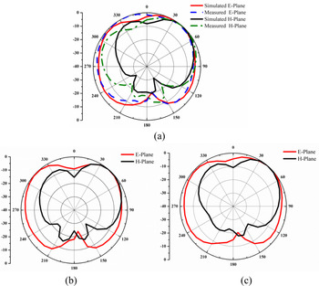
The implementation of the elliptical-shaped antenna is studied for various far field conditions. The following figures represents the radiation patterns of the proposed antenna with respect to E plane an H plane. Here, three distinctive far field conditions are used, those are φ = 0, φ = 90, and the outlines for these conditions are observed in Figs 11(a-c), respectively. Radiation of the proposed antenna at the frequency of 10.46GHz, the proposed antenna with MEMS ON state at the frequency of 10.57GHz, the proposed antenna at the frequency of 10. 53GHz.The radiation patterns of all the three conditions in E plane are observed as omni directional.
(a) Patterns of the proposed elliptical-shaped antenna. (b)Patterns of the proposed elliptical-shaped antenna with switch in ON state. (c) Patterns of the proposed elliptical-shaped antenna with switch in OFF state.

The normalized radiation patterns of the proposed elliptical patch antenna are shown in Fig. 11(a). The simulated patterns of the antenna are matched well with the measured results at 10.46 and 10.5 GHz, respectively. Due to measurement errors, there is a slight difference between the simulated and measured results.
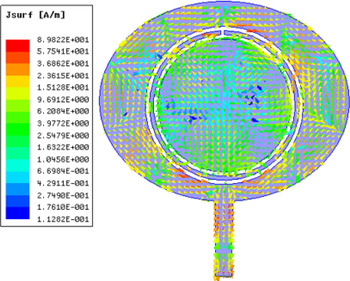
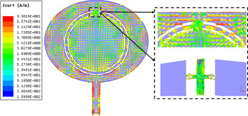
Figures 12 and 13 show the current distributions of the proposed elliptical microstrip patch antenna with and without switch. The losses are minimized due to elliptical shape.
Surface current distributions of the proposed antenna without switch at 10.46 GHz.

Surface current distributions of the proposed antenna with switch (OFF-state) at 10.57 GHz.

Figure 14 shows the simulated and measured radiation efficiency of the elliptical microstrip patch antenna. The deviation from simulated and measured results is due to issues raised during fabrication. Radiation efficiency is presented to validate the antenna performance.
Radiation efficiency of the elliptical patch antenna.

The simulated and measured gains of the proposed antenna are 6.13 and 5.9 dB, respectively, as shown in Fig. 15. For a better understanding of the proposed model antenna and higher gain obtained when compared to the other antenna models, see Table 3.
Gain versus frequency of the elliptical patch antenna.

Performance of the MEMS switch
MEMS switch analysis
In the process of design, the actuating voltage applied on the switch is unique which needs to be low and considered to be a challenging parameter in RF-MEMS; usually when the switches are activated, the metal beam is bent down and restores its elasticity to the original position. The beam in the upstate is subjected to duty electrostatic force and thus pull-in voltage expression can be given as:

where g is the maximum air gap maintained between the plates, k is the spring constant, and A is the overlapping area of beam and lower electrode when actuated; here, when

representing the maximum actuation voltage when the air gap between the upper and lower electrode reaches 1/3rd of its height, then the expression can be evaluated as

where A is the area of overlap.
Actuation voltage is defined as the voltage that is given to the upper beam and lower electrode.
RF performance of the device is evaluated with lumped elements. The typical values of the lumped components are important to notify. The ON and OFF states of the switch capacitance are the important ones which are given in the equivalent circuit. The ON-state capacitance is evaluated with the expression.
In the parallel plate switches, charges are implemented through charge carrier. Based on the overlapping area, parallel plate capacitance relies between the two capacitive plates. The total beam area is directly proportional to the total switch capacitance. Here, the term Cpp represents the ideal capacitance (parallel plate). It is important to support the minimal capacitance to attain the required frequency for the switch. The Cff simply relies upon the holes on the switch beam. Here, in the proposed shunt switch, the electric field moves across the switch beam and modifies the overall capacitance of the switch beam. However, the Cff can be observed across the upper surface of the plate and between the sides of the plates.

where C pp is the parallel plate capacitance and C ff is the fringing field capacitance.
When the switch is in ON state, the on capacitance must be low in order to keep the insertion loss minimum. The OFF-state capacitance is typical to calculate because when the membrane is in OFF state, it is not fully flat over the oxide layer. The switch OFF-state capacitance can be expressed as

The ON-state and OFF-state capacitance of the switch with aluminum nitride as a dielectric is 1.83 and 2.91 pF. The ON-state capacitance should be lower than the OFF-state capacitance.
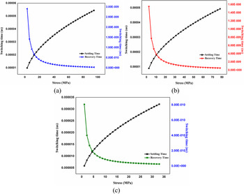
The deformation of beam with different beam thickness at 0.8, 1, and 1.2 μm is considered to evaluate the switch performance. To validate the switch three different beam thickness like 0.8, 1 and 1.2 µm are considered.and analysed) instead of (To validate the switch and for the material saving three analysis are ought to be considered for the switch after 1µm if the thickness is increased the beam cannot meet the required demand. The time required for a switch to toggle from ON state to OFF state can be expressed as


There are switching times concerned with switch. The first referred to pull-in time or the settling time, defined as the time taken to move the flexible beam to the bottom ground electrode through the voltage applied referred as pull-in voltage. The second referred to the pull-up time or the recovery time, the time taken by the beam to release from the pull-in position to its switched position by removing the voltage applied to the beam referred as pull-up voltage. Here the settling time and the recovery time of the switch are presented in Fig. 16. Due to the force applied on the switch, it undergoes three different stresses at overall, center and edge of the beam.
Switching time and recovery time of the proposed switch with different states (ON and OFF): (a) all over the beam, (b) at the center of the beam, and (c) at the edges of the beam.

In this section, the analysis is presented with switch on the proposed antenna. Switch performance is evaluated on the isolation, low return, and insertion loss. Therefore, by adjusting the geometrical parameters of the switch, the RF performance can be optimized. It is concerned with the return loss of −78 dB at 8 GHz and the insertion loss of −0.07 dB at 8 GHz frequency. By changing the dielectric height, the capacitance between the electrodes is changed, leading resonant frequency change. So, the dielectric layer thickness must be chosen between 0.1 and 0.5 to attain the required frequency range. The isolation performance of the proposed switch can be observed in the following figures. The isolation of −77 dB at the frequency of 8 GHz is obtained. From Figs 17 and 18, the performance can be observed. The actuation voltage calculated for the proposed switch is 7.9 V to actuate the top electrode to move from ON state to OFF state.
Isolation performance of the switch.

(a) Return loss and insertion loss of the proposed switch. (b) Actuation voltage and displacement curve.

The performance of the RF-MEMS switch related to the low return loss, insertion loss, and the improved isolation is −78, 0.07, and −77 dB at 8 GHz. The radiation patterns of the proposed elliptical antenna integrated with the switch are observed. The proposed SRR elliptical patch antenna is compared with the previous works in Table 3.
Comparison of the proposed SRR elliptical patch antenna with literature work

N/A, not available.
The proposed antenna is suitable for satellite applications and the optimization is carried out with HFSS. So, we consider only one resonant frequency band. The purpose of generating a single resonant band is reducing interference because the satellite communication antenna may have low losses. However, the proposed shape can be generated by a dual band with different optimization techniques.
Conclusion
This work proposes a novel type of elliptical-shaped patch antenna, and the characteristic of the antenna is controlled by the RF-MEMS switch. The impedance-matching technique performed for the antenna integrated with switch at ON and OFF states is examined. The proposed device return loss observed at different conditions (without, ON, and OFF switches) is presented as −37.6 dB at 10.46 GHz, −30 dB at 10.57 GHz, and −43 dB at 10.53 GHz, respectively. The actuation voltage obtained for the proposed switch is 7.9 V to actuate from up state to the down state of the switch. The fixed-fixed type RF-MEMS bridge is introduced to operate the antenna either at 10.46 or 10.57 GHz subjected to the position of the switch. The design of the elliptical-shaped antenna with switch geometry is simulated with HFSS electromagnetic simulator considering ideal MEMS switch. The fabricated prototype of the antenna is resonated at 10.5 GHz with the return loss of −35 dB which is considered to be a good agreement; there is a slight deviation between simulated and measured results.
Acknowledgements
This work was supported by the Science and Engineering Research Board (SERB), DST, India, Grant no: EEQ/2016/000754.
 Bokkisam Venkata Sai Sailaja received the Bachelor's degree in Electronics and Communication Engineering in the year 2012 from Anna University, the Master's degree in VLSI from K.L. University in the year 2018, and currently pursuing the Ph.D. degree on reconfigurable antennas using MEMS Research domain in K.L. University. She has published 11 international research publications and presented more than five conference technical papers around the world.
 Ketavath Kumar Naik received the B.Tech degree in Electronics and Communication Engineering (ECE) from Jawaharlal Nehru Technological University JNTU College of Engineering, Kukatpally, Hyderabad, India; M.Tech degree in Digital Electronics and Communication Systems from JNTU College of Engineering, Anantapur, India; and Ph.D. degree in ECE from the College of Engineering, Andhra University, Visakhapatnam, India. He is working as a Professor in the Department of ECE, Koneru Lakshamaiah Educational Foundation (deemed to be University), Guntur, India. He has sponsored research projects from the Department of Science and Technology (DST) worth of Rs. 7 856 000. He also received the “DST Young Scientist Award” in 2014 from the Government of India, and the “Best Paper Award” at the International Conference InCMARS 2008. He is the referee for Sponsored Research Proposals of DST, SERB, Government of India. He is the Associate Editor of International Journal of Electronics, Communications, and Measurement Engineering (IJECME), IGI Global, USA. He is a reviewer for various international and national journals and conferences such as IEEE Transactions on Antennas and Propagation, IEEE Access, IEEE Sensors, IET Electronics Letters, AEU-International Journal of Electronics and Communications, International Journal of Wireless Personal Communications, Engineering Reports, Journal of Ambient Intelligence and Humanized Computing, Journal of Electromagnetic Waves and Applications, IETE Journal of Research, International Journal of Applied Computational Electromagnetics Society, International Journal of Advanced Electromagnetics, etc. He is also a Referee of Sponsored Research Proposal of Science and Engineering Research Board (SERB), Department of Science and Technology (DST), Govt. of India. He has published over 75 research papers in reputed international and national journals and conferences. He has also authored five book chapters. He is a Fellow IETE and a Senior Member IEEE, etc. His research interests include ring arrays, phased-array antennas, microstrip antennas, conformal antennas, SRR, EMI/EMC, RF switches, and biomedical applications.