I. INTRODUCTION
Hexagonal planar arrays are capable of providing an optimum sampling strategy for signals which are band limited in a Fourier plane over a circular region [Reference Van Trees1]. Beside this, the arrays with hexagonal geometry are able to reduce the high sidelobe problems which arise in case of using circular configuration. The excellent scanning abilities of the hexagonal planar arrays along with the above-mentioned capabilities make it suitable to find applications in smart antennas for wireless communications and in satellite applications [Reference Van Trees1–Reference Mahmoud, El-Adawy, Ibrahem, Bansal and Zainud-Deen5]. Synthesis of hexagonal planar array appears in the literature [Reference Van Trees1–Reference Mahmoud, El-Adawy, Ibrahem, Bansal and Zainud-Deen5]. Synthesis of hexagonal planar array with the application of Gegenbauer polynomial for low sidelobe and high directivity has been reported in [Reference Goto2]. The radiation pattern of a hexagonal array with the elements in triangular lattice has been synthesis using a pattern of linear array [Reference Goto3]. Synthesis of hexagonal array for obtaining patterns having high gain and directivity is carried out by Gozasht et al. [Reference Gozasht, Dadashzadeh and Nikmhr4]. Mahmoud et al. [Reference Mahmoud, El-Adawy, Ibrahem, Bansal and Zainud-Deen5] have designed hexagonal and circular array with 18 half-wave dipole elements and evaluated complex excitation amplitude and phase using particle swarm optimization (PSO).
Synthesis of uniformly excited thinned array using deterministic approach is reported in [Reference Bucci, Isernia and Morabito6].
Different optimization algorithms such as genetic algorithm, PSO, etc. have been applied to a huge variety of electromagnetic problems especially for broadband, miniature, multiband, high-directivity antennas, and also for synthesis of different beam patterns from a variety of antenna arrays [Reference Johnson and Rahmat-Samii7–Reference Jayasinghe, Anguera and Uduwawala11]. Apart from these population-based optimization algorithms, several other techniques [Reference Van Trees1–Reference Goto2, Reference Gozasht, Dadashzadeh and Nikmhr4, Reference Bucci, Isernia and Morabito6] are reported in the literature to synthesize beam pattern from different array geometries.
In this paper, synthesis of a standard hexagonal array (SHA) [Reference Van Trees1] for generating two different beam patterns of a pencil beam and a square footprint over a bounded region is presented. Two different cases have been considered. In the first case, a pencil beam is generated by thinning [Reference Mailloux12–Reference Petko and Werner18] the array and in the second case a square footprint pattern [Reference Elliott and Stern19–Reference Eirey-Perez, Álvarez-Folqueiras, Rodriquez-González and Ares-Pena22] is obtained by properly modifying the array elements amplitudes, phases, and their corresponding states (“on”/“off”). The optimum values of the parameters for the two different cases are computed individually using artificial bee colony (ABC) [Reference Karaboga and Basturk23, Reference Karaboga and Basturk24] optimization and firefly algorithm (FA) [Reference Yang25, Reference Łukasik and Żak26]. A comparative analysis has been carried out between ABC and FA in terms of fitness value and the superiority of FA over ABC has been established for both the cases.
II. PROBLEM FORMULATION
The positions of the array elements are assumed to be fixed and all the elements have two states either “on” or “off”, depending upon whether the element is connected to the feed network or not. In the “on” state of an element, the amplitude and phase excitations are imposed through the feed network; and in the “off” state, the element can be assumed to be passively terminated to a matched load or an open circuited.
A pencil beam of the first case is obtained from the uniformly excited array by turning off some of the elements from the array i.e. by modifying the elements states. The process is known as array thinning and is widely employed to reduce the peak side lobe level (peak SLL) of the array. Typical applications of thinned arrays include satellite-receiving antennas that operate against a jamming environment [Reference Mailloux12], ground-based high-frequency radars [Reference Mailloux12], and design of interferometer array for radio astronomy [Reference Mailloux12]. The phase excitations of the array elements for the first case are assumed to be “zero” degree.
A footprint pattern with given specification is obtained from the array by appropriately modifying the elements amplitudes, phases, and their corresponding states. The inclusion of elements states in the synthesis method reduces the power consumption and simplifies the design process. The application of footprint patterns is involved in satellite communications, where coverage of a specified geographical region on earth surface is required while minimizing the radiation in other nearby regions.
Following the above procedures, two different beam patterns of pencil beam and a square footprint pattern with lower peak SLL have been achieved. The elements excitations in terms of amplitudes and phases and their corresponding states are assumed to have a quadrantal symmetry among themselves for the two different cases. The purpose of considering the symmetric excitations is to impose the required symmetry in the desired beam patterns.
In case of SHA, the relationship between the horizontal and vertical interelement spacing of the rows is
 $${d_y}=\displaystyle{{\sqrt 3 } \over 2}{d_x}.$$
Considering the horizontal interelement spacing d x = 0.5λ, the far-field pattern of the SHA as shown in Fig. 1 on the x − y plane can be expressed as [Reference Van Trees1]
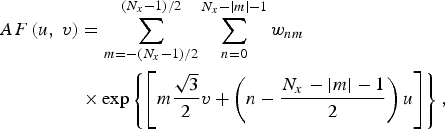 $$\eqalign{AF\left({u\comma \; v} \right)& = \sum _{m = - \lpar {N_x} - 1\rpar {\rm /}2}^{\lpar {N_x} - 1\rpar {\rm /}2} \sum\limits_{n = 0}^{{N_x} - \left\vert m \right\vert - 1} {{w_{nm}}} \cr & \times{\rm exp}\left\{{\left[{m\displaystyle{{\sqrt 3 } \over 2}v + \left({n - \displaystyle{{{N_x} - \left\vert m \right\vert - 1} \over 2}} \right)u} \right]} \right\}\comma \; }$$
where w nm is the complex weight of the nmth element. N x is the number of elements in the horizontal row passing through the origin (Fig. 1). The individual elements in a particular row is indexed with the variable n, which ranged from n = 0 to N r − 1; where, N r is the number of elements in a particular row [Reference Van Trees1] and is defined as [Reference Van Trees1] N r = N x− |m|. Each row is indexed by the variable m, ranges from −(N x − 1)/2 to (N x − 1)/2. The direction cosines are u = sin θ cos φ and v = sin θ sin φ where θ and φ represent the polar and azimuth angles, respectively.
Geometry of a hexagonal planar array with 37 isotropic elements.

The design objective of this paper is to minimize the fitness functions for the two different cases using ABC and FA which are defined as follows:
 $$F1=\mathop {{\rm max}}\limits_{\lpar u\comma v\rpar \in {A_1}} \left\{{A{F_{dB}}\lpar u\comma \; v\rpar } \right\}\comma$$
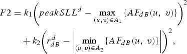 $$\eqalign{F2 & ={k_1}{\left({peakSL{L^d} - \mathop {{\rm max}}\limits_{\lpar u\comma v\rpar \in {A_1}} \left\{{A{F_{dB}}\lpar u\comma \; v\rpar } \right\}} \right)^2} \cr & \quad +{k_2}{\left({r_{dB}^d - \left\vert {\mathop {{\rm min}}\limits_{\lpar u\comma v\rpar \in {A_2}} \left\{{A{F_{dB}}\lpar u\comma \; v\rpar } \right\}} \right\vert } \right)^2}\comma \; }$$
where F1 is the fitness function for the pencil beam of case I and F2 is the fitness function for the square footprint pattern of case II. peakSLL d represent the desired values of the peak SLL and r dBd denotes the response ripple for square footprint pattern.
In equations (3) and (4), max(u,v)∈A 1 {AF dB(u,v)} is responsible for determining peak SLL of the obtained beam pattern in the u–v plane, where A 1 represents the angular region of the sidelobes which is outside the main beam region of the pattern. The computed value of peak SLL in this manner is subtracted from the desired values of the peak SLL and finally to increase the weightage of the resulting term, its square is taken. The same procedure is adopted for determining the ripple parameter in equation (4). The term |min(u, v)∈A 2{A F dB(u, v)}| determines the obtained ripple for the square footprint pattern within the angular region A 2, which is defined as −0.12 ≤ u ≤ 0.12 and −0.12 ≤ v ≤ 0.12. k 1 and k 2 are the weighting factors to give relative importance of each of the terms. The values assigned to k 1 and k 2 are 1 and 100, respectively.
III. ALGORITHM OVERVIEWS AND PARAMETRIC SETUP
A) Overview of ABC algorithm
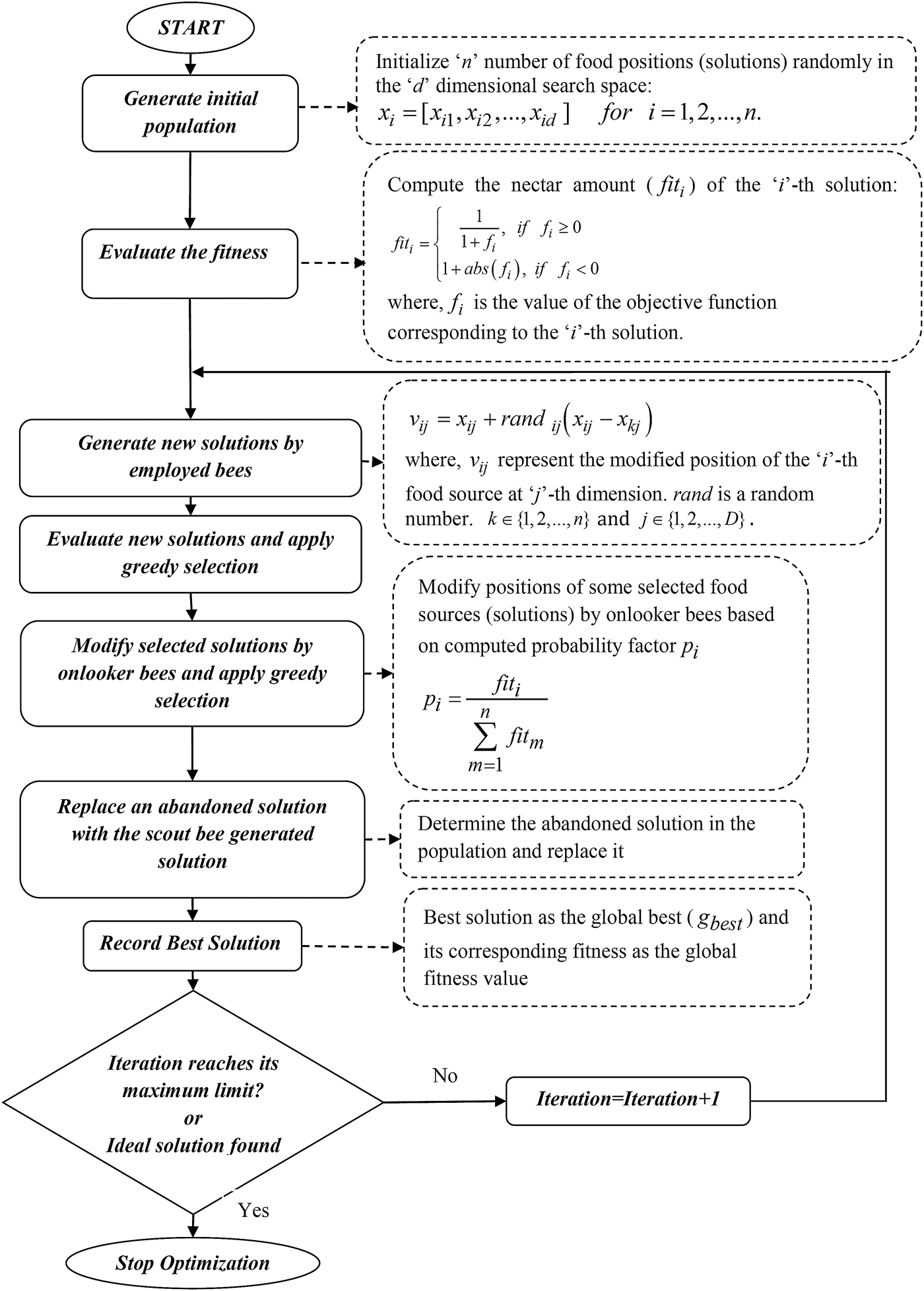
ABC algorithm is swarm-based optimization algorithm developed by Karaboga and Basturk [Reference Karaboga and Basturk23, Reference Karaboga and Basturk24]. In ABC algorithm, the solutions of an optimization problem are denoted by the positions of the food sources around a colony of artificial bees and the search ability of ABC lies on different behaviors of the three groups of bees: employed bees, onlookers, and scouts. The algorithm can be summarized in the flowchart of Fig. 2.
Flowchart of ABC algorithm [23, 24].
B) Overview of FA
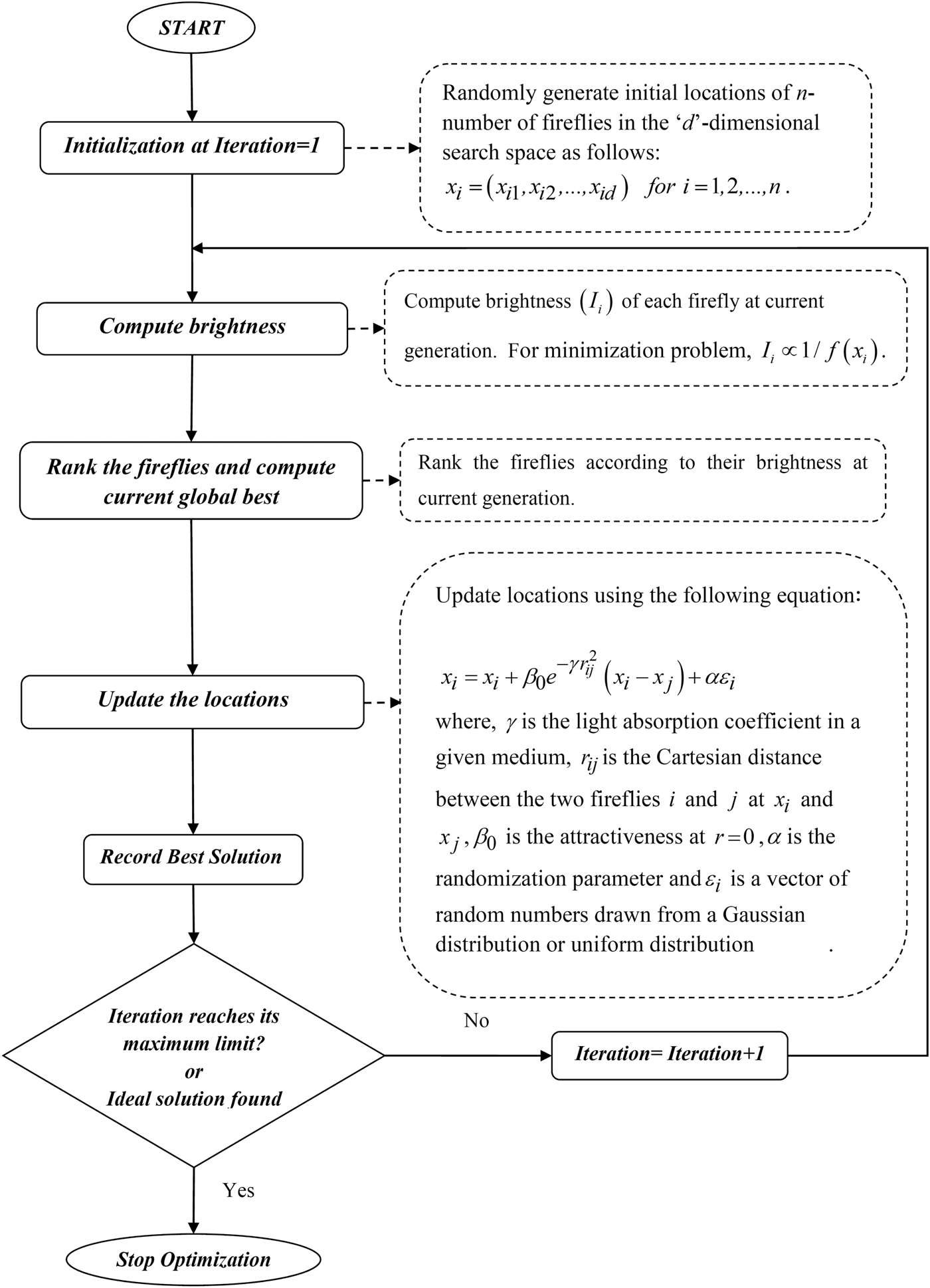
FA is a swarm-based optimization algorithm developed by Xin-She Yang [Reference Yang25, Reference Yang27]. The algorithm relates the flashing characteristics of the fireflies with the objective function and it was developed from the study of the behavior of how fireflies communicates. The algorithm considered glowing fireflies as the search agents and each firefly is characterized by two parameters: its location in the d-dimensional search space and its light intensity or brightness. Depending upon their brightness, the fireflies changes their location and the algorithm approaches toward its optimum solution.
The algorithm can be summarized in the flowchart of Fig. 3.
Flowchart of FA [25–27].
C) Details of parametric setup
A hexagonal planar array of total 169 isotropic elements is considered. The number of elements in the horizontal row through the origin is 15, i.e. N x = 15.
For the first case of pencil beam, as the design problem is to find out an optimum set of elements state; the individual of the population for both ABC and FA is considered as follows:
 $$P=\lsqb {S_1}\, {S_2}\, ...\, {S_X}\rsqb .$$
For the second case of square footprint pattern, the design problem is based on finding out optimum set of elements amplitudes, optimum set of elements phases, and optimum set of the elements states; the individual of the population for both ABC and FA are considered as follows:
 $$P=\lsqb {I_1}\, {I_2}\, ...\, {I_X}\, {\alpha _1}\, {\alpha _2}\, ...\, {\alpha _X}\, {S_1}\, {S_2}\, ...\, {S_X}\rsqb .$$
As the state of a particular element is either “0” or “1”, a mapping from real space to binary space for the elements states in each of the individuals for both ABC and FA has been performed using the sigmoid function restriction Sig(S i) as follows:
 $$Sig\left({{S_i}} \right)=\displaystyle{1 \over {1+{\rm exp}\left({ - {S_i}} \right)}}\comma \; \quad i=1\comma \; 2\comma \; ...\comma \; X\comma$$
 $${S_i}=\left\{{\matrix{ 1 & {{\rm if}\; rand \leq Sig\left({{S_i}} \right)\comma \; } \cr 0 & {{\rm otherwise\comma \; }} \cr } } \right.$$
where rand is a uniformly distributed random number between [0,1] and Sig(S i) denotes the probability of bit S i taking “1”. If S i becomes a vector of zeros or ones, the solution is regarded as infeasible for both ABC and FA.
The limits of the variables are defined as follows:
 $$0.05 \leq {I_m} \leq 1 \quad {\rm for}\; m=1\comma \; 2\comma \; \ldots\comma \; X\comma$$
 $$ - \pi \leq {\alpha _m} \leq \pi \quad {\rm for}\; m=1\comma \; 2\comma \; \ldots\comma \; X\comma$$
 $$0 \leq {S_m} \leq 1 \quad {\rm for}\; m=1\comma \; 2\comma \; \ldots\comma \; X.$$
The lower limits of the amplitudes are kept at 0.05 to maintain the DRR (dynamic range ratio) of the excitation amplitudes between 1 and 20. As the elements excitations and their states pause a quadrantal symmetry among themselves individually, the number of different variables in each of the computed set becomes 48. So for both the cases X = 48. The search space dimension for the two cases becomes 48 and 144, respectively.
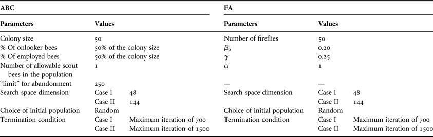
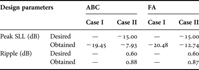
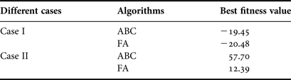
The other parametric setups of the ABC and FA for the proposed problem are set based on the guidelines provided in [Reference Karaboga and Basturk23–Reference Yang27] and are given in Table 1. The desired specifications of the parameters required for obtaining pencil beam patterns of case I and square footprint pattern case are given in Table 2.
Parametric setup of the ABC and FA.
Desired and obtained results for cases I and II computed using ABC and FA.
IV. SIMULATION RESULTS
The results presented in this section are the best set of results obtained from 20 different runs of ABC and FA while minimizing the fitness function of each individual case. The desired and obtained values of the design parameters for two different cases are listed in Table 2.
The beam pattern of the uniformly excited array and zero phases among the elements are shown in Fig. 4. The array with uniform excitation among the elements and constant phase gives peak SLL of 16.47 dB.
Far field pattern of a uniformly excited planar hexagonal array of 169 numbers of isotropic elements.
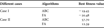
It can be observed from Table 2 that the obtained values of peak SLL for the pencil beam pattern of case I using ABC and FA are −19.45 and −20.48 dB. Figures 5 and 6 present the thinned array of best design using ABC and FA and their corresponding beam patterns are shown in Figs 7 and 8, respectively.
Thinned array using ABC (case I).
Thinned array using FA (case I).
Far field pattern of the thinned array using ABC (case I).
Far field pattern of the thinned array using FA (case I).
The obtained values of peak SLL for the square footprint patterns using ABC and FA are −7.93 and −12.74 dB corresponding to a desired value of −15 dB. The obtained response ripple using ABC and FA are 0.88 and 0.87 dB corresponding to their desire value of 0.60 dB. The state of array elements for the footprint patterns is shown in Figs 9 and 10 and their corresponding beam patterns are shown in Figs 11 and 12, respectively.
State of the array elements computed using ABC for obtaining square footprint pattern (case II).
State of the array elements computed using FA for obtaining square footprint pattern (case II).
Far field pattern of the optimized array with a target of a square footprint within the range of −0.12 ≤ u ≤ 0.12 and −0.12 ≤ v ≤ 0.12 using ABC.
Far field pattern of the optimized array with a target of a square footprint within the range of −0.12 ≤ u ≤ 0.12 and −0.12 ≤ v ≤ 0.12 using FA.
The optimum excitations of the switched-on elements in terms of amplitudes and phases for the rectangular footprint pattern of case II using ABC and FA are shown in Figs 13 and 14, respectively (Table 3).
Excitations of the switched-on elements computed using ABC for generating square footprint pattern (“case II”): (a) amplitude distribution and (b) phase distribution.
Excitations of the switched-on elements computed using FA for generating square footprint pattern (“case II”): (a) amplitude distribution and (b) phase distribution.
Total switched-on elements and DRR for cases I and II.
The convergence characteristics of the ABC and FA presented in this paper for all the cases are in terms of best fitness value versus generations for the best run of each algorithm (best out of 20 different runs).
Figure 15 shows the convergence of ABC and FA for case I and Fig. 16 shows the convergence of ABC and FA for case II. From Figs 15 and 16, it can be seen that the performance of FA over ABC is much better for the minimization of the fitness functions for both the cases (Table 4).
Convergence characteristics of ABC and FA for case I.
Convergence characteristics of ABC and FA for case II.
Comparative performance of the FA and ABC.
V. CONCLUSIONS
Two different swarm-based global optimization techniques have been applied to synthesize beam patterns of a hexagonal planar array of isotropic elements. The proposed method is capable of producing beam patterns that meet the desired specification to construct a pencil beam by thinning the uniformly excited array and a square footprint pattern over a bounded region by appropriately modifying the elements amplitudes, phases, and their corresponding states.
The performances of the two algorithms are also compared in terms of minimizing the fitness functions for the two different cases and the superiority of FA over ABC is established. The fitness functions are formed in such a manner to get satisfactory output. The termination conditions of FA and ABC are chosen by specifying a maximum number of iterations after which the probability of getting improved solutions is negligible.
Finally, the inclusion of elements states improve the overall power consumption of the system and the low value of DRR reduces the design complexity of the feed network.
The proposed technique can also be extended to generate other types of footprint from hexagonal planar array like rectangular, circular, and U-shaped footprints which often required in satellite communication applications.
 Anirban Chatterjee received his M. Tech and PhD from National Institute of Technology, Durgapur, India in 2009 and 2013 respectively. His research interest includes Array Antenna synthesis, Soft Computing, and Electromagnetics. He has published 11 research papers in international journals and 6 papers in international conferences.
 Debasis Mandal completed his M.Sc in Electronics, 2008 and M.Tech in Electronics and communication engineering in the year of 2010. Currently he is pursuing his Ph.D degree from National Institute of Technology, Durgapur, India and also working as an Assistant Professor in the department of Electronics and Communication Engineering at Bengal College of Engineering and Technology, Durgapur, India. He has published two research papers in international Journals and one research paper in International Conference. His research interest includes Array Antenna synthesis, Soft Computing, and Electromagnetics.