I. INTRODUCTION
Gray cast iron (GCI) has been utilized as a wear resistance material for applications where the applied loads are very high and cyclic. Rolling contact fatigue (RCF) is a common phenomenon of great practical significance to many engineering applications involving concentrated contacts, such as gears, rolling guides, and rails.Reference Polonsky, Chang, Keer and Sproul1–Reference Carroll and Beynon4 The service life of this and other types of guideway are often limited by RCF failure. Pit formation and surface peeling caused by RCF are serious problems in guideway applications, as well. Generally, to prolong the fatigue life, components such as rolling guides, which are typically suffered high alternating stress, can be modified by embedding high hardness steel into GCI substrate to benefit from the combined properties of both materials. Joining short steel pieces together is a complex process and formation of junctions makes defects more prone to occur. At this background, a facile and economical method of improving the fatigue wear resistance (FWR) of GCI is urgently necessary. Previous researchReference Shi, Hu and Zheng5 has suggested that GCI performs satisfactorily under RCF after surface treatment, though stress concentration is likely to be raised at the flake graphite tips, creating natural defects. However, abrupt discontinuity in the hardness between the coating and matrix is determined a primary cause of poor adhesion, leading to shedding and splitting of the coatings for this technology. An optimized method of surface treatment that successfully improves FWR should be explored in effort to remedy this.
Over billions years of natural selection and evolution, biological structures have gradually adapted to their living environment.Reference Zhang, Xu, Xuan, Wang and Tu6 The nacreous layer of a shell, a natural compound material, for example, possesses highly favorable mechanical properties. Nacreous layers are composed of 96% v/v of aragonite (hard) and 4% v/v protein (soft). The hardness of the nacreous layer is two times that of common aragonite; due to its composition of both soft and hard parts, nacreous layers are 1000 times tougher than plain aragonite. Kamat et al.Reference Kamat, Su and Ballarini7 studied the deformation and fracture of nacreous layers with bending resistance tests, and found that cracks were unable to penetrate the aragonite layer directly and caused deflection at the layer's interface. In a related study, Pederson et al.Reference Pederson, Ruberti and Messersmith8 demonstrated that material with the nonsmooth surface in accordance with the unique construct of shell structures showed superior mechanical behavior. Enlightened by the bionic method, the authors attempted to improve the FWR of materials by modifying sample's surface to imitate the surface structure of pangolin which exhibited excellent wear resistance at its life. With respect to the bionic principles, the pangolin surface was abstracted to a toughening structure with alternately soft and hard characteristic. As proven by Dubey and Yadava,Reference Dubey and Yadava9 laser treatment is an effective method of surface modification, characterized by high hardness, unaltered composition, and other favorable properties. High-energy beam remelting may further improve the properties of metallic compounds without seriously affecting the properties of the base material, because the maximum depth of the reinforced layer is only few millimeters. Additionally, previous studies have observed fatigue failure to occur at the surfaces and subsurfaces of materialsReference Zhang, Xu, Xuan, Wang and Tu6,Reference Seo, Kwon, Lee and Choi10,Reference Ringsberg11 ; it is thus reasonable to assert that laser remelting (LM) is positive to the improvement of FWR. A considerable drawback to this technology, however, is the formation of heterogeneous microstructures due to the nonuniform distribution of carbon, which limits FWR improvement.
Various reinforced phases are formed in the correspondingly treated region as a result of laser treatment,Reference Li, Wang, Zhang, Han and Han12 including martensite, austenite, ledeburite etc., due to carbon trapped during rapid resolidification. Hence, this study developed and used a laser cladding (LC) method in effort to artificially supplement the elements required to manage insufficient chemical composition. Carbon powder served as the coating. After laser depositing, FWR under both LM and LC were compared, and the influence of carbon powder thickness was studied by self-controlled fatigue wear testing. Additionally, the wear behavior of samples was also investigated, and a distinct FWR mechanism was proposed according to the results.
II. EXPERIMENTAL
A. Experimental original materials
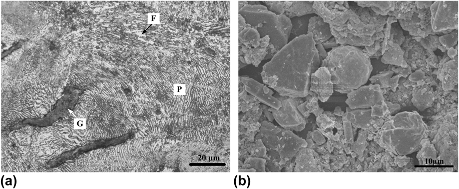
The used GCI was cut from the rail of a machine tool by electric spark machine (DK7732; Huadong Group, Taizhou, China). The nominal chemical composition of GCI used was: 3–3.2 wt% C, 1.5–1.8 wt% Si, 0.7–0.9 wt% Mn, less than 0.15 wt% P, less than 0.12 wt% S and Fe balanced. The microstructure (etched by 5% nital and polished by standard procedure) as shown in Fig. 1(a) revealed that the original GCI microstructure consisted of flake graphite (G) surrounded by ferrite (F) and pearlite (P). The bulk material hardness was 158 HB 10/500 and its pearlite matrix had 260 HV0.2. The carbon powder with purity of 98% and uncertain size [Fig. 1(b)] was used as coating material.
The microstructure of (a) PM by OM; (b) carbon powder by FESEM.

B. Preparation of specimens
1. Preparation of original samples
Samples were cut with dimensions of 120 mm × 15 mm × 5 mm (L × W × H) by electric spark machine. Polyvinyl alcohol was utilized as bonding material to prevent power from being splashed while laser processing. Before surface treatment, the covered coatings were polished by silicon carbide to required thickness. The effect of prepared coating thickness prior to LC on the FWR of GCI was experimentally investigated by observing five independent groups, including a group of parent material (PM) for comparison with the remaining treated samples. Among the treated specimens, one group without coating was treated by laser (LM) and the others covered in different thickness (s) of coating were irradiated by laser (LC). Each group included three identical samples for repetitive tests. Groups were marked No. 1–5 according to processing condition as listed in Table I. A cross-section of the coated sample was shown in Fig. 2(a). To avoid the effect of artificial defects (such as scratches) on fatigue wear lifetime, the samples were mechanically polished using progressively finer grades of silicon carbide papers up to 2000 grit.
Marked numbers according to the thickness of precoating.

(a) The cross-section of sample with coating before laser treatment; (b) the surface profile after laser depositing.
2. Laser treatment
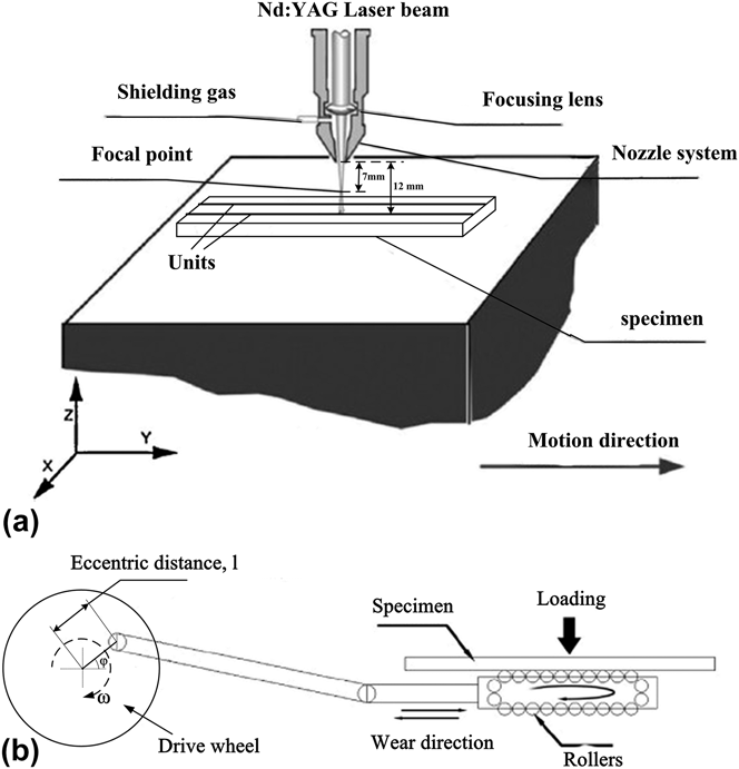
In this study, a Nd:YAG laser, with wave length of 1.064 μm and maximum power of 300 W, was utilized for surface modification under an argon gas shield, as the schematic diagram shown in Fig. 3(a). The laser head was vertically mounted in the Z-direction, and was adjustable. The work-bench was able to move along X, Y, and Z axes, or rotate on a given X–Y plane. During laser processing, the parameters were given as follows: pulse duration of 5.0 ms, frequency of 9 Hz, laser input energy density of 6.84 J/mm2, and an approximately circular spot size about 1 mm in diameter. Circulating cooling water was cycled in the interior of the machine to protect the machine from overheating, maintaining temperature at approximately 20 °C. The motion speed of the work-bench along the length of sample (Y axes) was 0.3 mm/s to produce stripy regions, two of which were processed in 5 mm center space. The sketch of modified surface was revealed in Fig. 2(b). The laser-treated region is referred to below as a “unit.”
The sketches of (a) laser processing system; (b) fatigue wear system.
C. Experimental details
1. Examinations of unit
Following surface modification, cross-sections of treated samples were cut parallel to the laser direction and subsequent standard methods of metallography were carried out. An optical microscope (Axio Imager A2m; Carl Zeiss Jena, Oberkochen, Germany) was utilized for preliminary study of the details of units. Micromesh microstructure analysis was then performed by means of Zeiss-Evo18 scanning electronic microscope (SEM, JSM-5500LV; JEOL Ltd., Tokyo, Japan) and field emission scanning electronic microscope (FESEM, JSM-6700F; JEOL Ltd., Tokyo, Japan). Phases and compounds formed in the unit were identified by D/max-RC x-ray diffraction (XRD) with Cu Kα radiation operated at the voltage of 40 KV, current of 40 mA, and scanning rate of 4°/min. Microhardness of the unit cross-section was measured by a Vickers Microhardness Tester (model 5104; Buehler Co. Ltd., Chicago, Illinois) at a load of 200 g and a dwell time of 10 s. Tensile and compressive tests were performed on samples by Material Testing Systems (MTS 810; MTS Systems Corporation, Eden Prairie, Minnesota).
2. Fatigue wear test
RCF tests were conducted on a self-controlled man-made machine [Fig. 3(b)] at room temperature. Runs were lubricated with SAE 46 machine oil. An elastohydrodynamic film was formed at the contact region that reduced the strain and friction coefficient. The samples were mounted in the back of loading station supported by ten trusted rollers (Ф5 × 11). A constant loading of 80 N would be transformed to samples' surface through a narrow contact area, which the generated pressure was well below that necessary to cause yielding. As shown in sketch, the rolling bearing and an eccenter were connected by a metal rod. By the rotation of eccenter, the roller bearing was actuated on the samples' surface back and forth. In present study, the rotation speed of eccenter was set at 30 rpm, corresponding to the instantaneously horizontal velocity (v) of the roller bearing which can be expressed as:
 $$v = \omega \cdot l \cdot \sin \varphi \quad ,$$
where ω denoted the angular velocity of drive wheel (180°/s), l was the eccentric distance (35 mm) that indicated the amplitude of back and forth path to be 35 mm, and φ was the deflection angle ranged 0°–360°. With respect to the calculated value of v, the positive and negative sign were presented the forwards and backwards of roller, respectively. Prior to each testing, the average weight of each group was measured by electronic balance with a precision of 0.1 mg. Similarly, the testing was interrupted to measure the mass of sample after 70 h, as well. It should be noted that sample was ultrasonically cleaned with acetone and blow-dried before mass measurement. The followed average mass loss (ML) of each group was recorded. Subsequently, the worn surfaces profiles were detected by optical microscope and SEM. According to the combination of ML and worn surfaces, the mechanisms of FWR improvement and various defect formations were correspondingly discussed, respectively.
III. RESULTS AND DISCUSSION
A. Morphology and dimensions of the melted zone
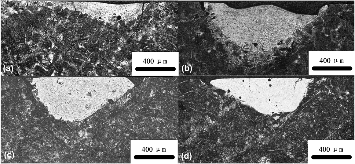
During the laser treatment processing, the temperature distribution of material cross-section was regular in laser beam direction. According to Li et al.Reference Li, Wang, Zhang, Han and Han12 who previously reported the temperature distribution during laser processing by finite element (FE), the isotherms presented an inverted parabola shape and the temperature gradually decreased outward from the heat source, as shown in Fig. 4. By the irradiation of high-energy laser beam, material elements were heated and subsequently resulted in phase transformation. In light of this, the cross-sections of created units (by LM and LC) showed inverted parabola shape, where the top of each unit was wider than its bottom, implying the temperature field feature, as the so-called units shown in Fig. 5. More specifically, a zone was experienced rapidly melting and solidification causing phase transformation while the other zone was undergone phase transformation without melting. According to the temperature field, the region under temperature higher than the melting point was defined as remelting zone (RZ), and the region under temperature lower than the melting point but higher than 727 °C underwent phase transformation without melting, was defined as transition zone (TZ). Additionally, the tempering effect, (confirmed by micro-hardness measurement in previous researchReference Jiang, Xue and Wang13), was overwhelmed in the area under temperature lower than 727 °C. However, the tempering zone was not taken into account in this study, as the scale was very narrow. Therefore, by the changed temperature in cross-section, the distinct regions in units were apparent in visual, including RZ and TZ.
The draft cross-section of unit according to Li et al.Reference Li, Wang, Zhang, Han and Han12
The actual cross-section morphologies of units with different coatings thickness in laser parametres: pulse duration 5.0 ms, frequency 9 Hz and laser input energy density 6.84 J/mm2. (a) without coating; (b) 0.1 mm; (c) 0.2 mm; (d) 0.3 mm.
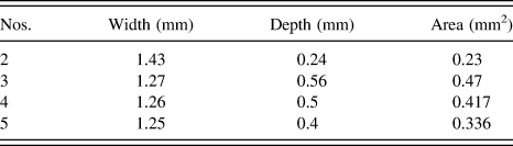
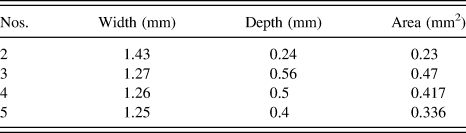
Table II indicated the dimensions of the laser remelting unit (LMU) and laser cladding unit (LCU). For both LM and LC, because the material element in TZ was not melted and subsequently failed to make a distinct boundary between TZ and the substrate, the measured dimensions were the statistic results of RZ. In comparison, the LMU melt pool was wider but shallower than that of the LCU; however, the area of LMU was apparently smaller than that of the LCU. Among the LCUs, the width was similar in different coating thickness, while the depth and area decreased in inverse proportion to coating thickness. Because the sample's surface was covered with black carbon powder, the covered surface was correspondingly subjected to higher power density as increased laser absorptivity, which resulted in large volume fraction of remelted region on LC sample compared to that on LM sample. These results were in accordance with reports by Benyounis,Reference Benyounis, Fakron, Abboud, Olabi and Hashmi14 in which low power density resulted in wider melt zone and little penetration while high power density produced a deep and narrow melted zone. What's more, with respect to the samples treated by LC, the created surface absorptivity and power density were completely identical. However, as known, a portion of heat would be consumed by the carbon coating during the thermal transmission in vertical direction. In light of the regular of LCU dimensions, this can be considered as the reason that the unit depth and area of LCUs were sensitive with the increase of coating thickness. In spite of the heat consumption by coating, the areas of all LCUs were always larger than the area of LMU. In other words, the level of increased unit area caused by increased surface absorptivity was more dominant than that of decreased unit area due to coating heat consumption.
Dimensions of laser remelted GCI processed in the laser parameters: pulse duration 5.0 ms, frequency 9 Hz and laser input energy density 6.84 J/mm2.
B. XRDs and microstructure characteristics
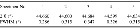
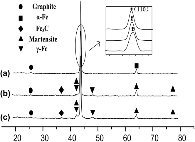
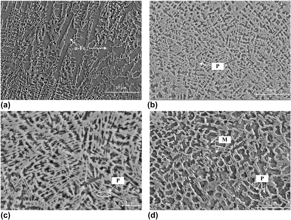
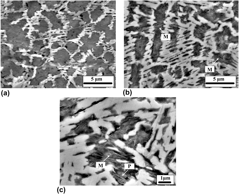
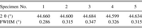
Owing to the high solidification rate of laser processing, the phases formed in the units were detected by means of XRD, and the microstructure characteristics of units were detected by SEM and FESEM. The parameters of major peaks were listed in Table III, in which demonstrated that the common 2-Theta of major peaks was about 44.6°. Nevertheless, slight differences in 2-Theta were an objective probability, due to the existence of residual stress (compressive or tensile) caused by phase transformation.Reference Grum and Šturm15 Broadening full width at half maximum (FWHM) of the treated specimens suggested the refinement of grain size, and LCU grain size likely decreased with increasing coating thickness, reaching similar FWHM as the LMU at coating thickness of 0.3 mm. Additionally, almost identical new phases, such as martensite and retained austenite, were demonstrated in the diffractograms (Fig. 6), which performed the role of reinforced phase in LMUs and LCUs. At the duration of laser treatment, the phase transition process could be validated as follows. When the surface got remelted, most of the α-Fe (bcc) transformed to γ-Fe (fcc) by trapping carbon, and subsequently transformed to martensite (M) or retained austenite (Ar) while some α-Fe kept its original phase in the absence of carbon diffusion. Consequently, the LMU microstructure [Fig. 7(a)] was irregular and nonuniform as absent carbon diffusion, which had a negative effect on mechanical properties. Conversely, the microstructures of LCUs were sufficiently uniform and regular in comparison with LMU, as illustrated in Figs. 7(b)–7(d). Due to the fact that external carbon was introduced into melted pool to supplement adequate carbon by thermal stress or laser beam impact, the ferrite in poor carbon region could trap the supplied carbon resulting in the transformation of martensite or austenite. Although the grain size in LCU (No. 5) was similar to that of LMU, LCU particles were more regular, uniform, and compact in comparison with the latter. However, in both LMU and LCU, similar dendrite structures throughout the melt zone were characterized by hypoeutectic dendrites with long primary and secondary arms. There was, additionally, complete dissolution of flake graphite and re-solidification of the hypoeutectic structure in RZ. Nevertheless, the spaces between secondary arms in LCU samples were much smaller than those in LMU. Under high magnification, the interior of the dendrites lacked M or P in the LMU [Fig. 8(a)], in accordance with previous research results,Reference Benyounis, Fakron, Abboud, Olabi and Hashmi14 but in LCU showed a considerable amount of martensite and pearlite [Figs. 8(b) and 8(c)].
Information of lattice plane (110) according to XRD.
XRD before and after laser depositing: (a) untreated sample; (b) treated sample by laser remelting; (c) treated sample by LC.
Microstructures of units with different coatings thickness by FESEM: (a) without coating; (b) 0.1 mm; (c) 0.2 mm; (d) 0.3 mm.
The microstructure of units by SEM: (a) LMU; (b) LCU; (c) interior detail of dendrites by LC.
Figure 9 depicted the details of interfaces between RZ and TZ of LMU and LCUs by FESEM. For the LMU and LCUs, TZ and RZ were clearly observed to be metallurgically bonded, and compositions of cementite (Fe3C) and abnormal ledeburite (Ld′) were formed in RZ. In addition, as visible in the micrograph of Fig. 9(a), a distinct interface was observed as well as martensite in TZ. With respect to LCUs, martensite content in TZ reduced with increased coating thickness until completely disappearing at 0.3 mm thickness, which instead was full of sorbite in the nominal TZ. Evidenced by these results, the thickness of coating was also considered to affect cooling rate to some extent. When the surface was exposed in the air or with thin coating, wide temperature gradient existed in RZ resulting in high cooling rate that induced the phase transformation. Surfaces with thick coating, conversely, showed relatively low cooling rate and subsequent narrow TZ with less martensite. Once coating increased to a critical value (0.3 mm), cooling rate was reduced even farther, and the martensite completely disappeared in TZ, owing to the fact that the thick coating consumed more heat or played an excellent heat preservation layer. This suggested that TZ formed in thick coating was suffered quenching and tempering effects during heating and cooling; in other words, that it normalized, resulting in the occurrence of sorbite.
The boundary of RZ and TZ of units in different coating thickness by FESEM: (a) without coating; (b) 0.1 mm; (c) 0.2 mm; (d) 0.3 mm.
C. Micro-hardness of units
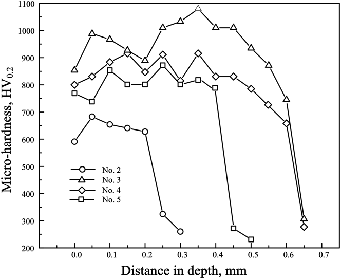
According to refined crystalline strengthening mechanisms, microscopic particle refinement reflected the increased micro-hardness on the macro. Micro-hardness tests were performed on the LCU and LMU cross-sections, showing micro-hardness profiles along the path from the melt surface to the bottom of melt pool (Fig. 10). Interestingly, all plots rose and then dropped down from top to bottom of the melt pool, indicating the oxidation reaction of carbon in the surface or subsurface inducing the formation of decarburization layer. Similar results were observed by Wang and Bergmann.Reference Wang and Bergmann16 Another notable aspect of the test results was that micro-hardness significantly increased under laser deposition, and it was more effective by LC, as high as 780–850 HV0.2 in RZ. Additionally, micro-hardness of both surfaces and subsurfaces of samples with thin coating was consistently higher than those with relatively thick coatings, ranked No. 3 > No. 4 > No. 5. Depending on the refined grain size and the microstructure in units, this phenomenon seemed to be reasonable.
The micro-hardness against the depth of units.
D. Improvement of tensile and compressive resistance
Figure 11 indicated the results of tensile and compressive tests executed on samples. Figure 11(a) markedly depicted the stress–strain plots of samples ranged Nos. 1–5. It was clearly seen that all the samples performed inconspicuous yield point and low fracture elongation, implying GCI to be a fragile material. According to the empirical view that yield stress approximated fracture stress for fragile materials, the yield stress of treated samples was subsequently sorted as: No. 3 > No. 4 > No. 5 > No. 2 > No. 1. That can be interpreted that laser deposition (either LC or LM) could significantly improve the yield stress of sample as the refinement of particles, and the improved level was intensively sensitive to grain size (explainable according to Hall–Petch LawReference Hugo, Kung, Weertman, Mitra, Knapp and Follstaedt17). Additionally, although the unit grain sizes of No. 5 and No. 2 were the same, the former exhibited higher yield stress due to its more compact and uniform crystal compared to the letter, as mentioned above. As a conclusion, the microstructure was another factor affecting the yield stress of sample. What's more, an unexpected result was demonstrated that fracture elongation was reduced by increased micro-hardness among LC treated samples. Even so, the fracture elongations of LC treated samples were consistently more favorable than those of LM treated samples or untreated samples. Figure 11(b) showed the axial displacement of the samples response to axial force during elastic deformation. This plot implied that the abilities of samples' axial deformation resistance had the same sequence with their yield stress. It can be concluded that the ability of compressive deformation resistance was determined by yield stress. Consequently, by the arrangement of refined particles and increased volume fraction of reinforced phase, the both of tensile and compressive deformation resistances were correspondingly improved.
The results of mechanical properties tests by MTS: (a) tensile plots; (b) compressive plots.
E. Mechanism of FWR improvement
Figure 12 demonstrated the average ML of each group at the end of test (about 1.26 × 10⁶ cycles). The results clearly showed that laser surface treatment was beneficial for FWR, particularly under LC. In addition, the influence was varying with various coating thickness that the level of improvement reduced in inverse proportion to coating thickness. There were several reasons behind that. Owing to the correspondingly improved tensile and compressive resistance of samples, the FWR enhancement presented in this study was therefore reasonable in accordance with a study by Kapoor,Reference Kapoor18 in which the Coffin–Manson Law was used to describe RCF failure ascribed to accumulated plastic deformation (combination of shear strain and axial strain). In the view of fracture, characterized by crack initiation and propagation, FWR was improved to some extent by increased fracture strength, as well. Generally, micro-cracks preferred to occur in graphite, which was usually regarded as the natural hole, suggesting that eliminating graphite can effectively prolong crack initiation.Reference Shi, Hu and Zheng5 What is more, the graphite also formed a connection bridge between adjacent cracks, allowing micro-crack propagation in the least energy as possible.Reference Chen, Zhou, Zhao, Zhang, Lu, Yang and Zhou19 When cracks propagated in the region without graphite (treated area), the generally developed paths of crack were intergranular and transgranular. By the refinement of crystal, the propagation of crack was more frequent deflection and more difficult to cross fine crystal compared to coarse crystal. Thus, the both ways of crack propagation would increase the absorbed energy, and subsequently improved the fatigue life. Therefore, once the graphite disappeared, crack initiation and propagation was effectively hindered and fatigue life was accordingly enhanced.
Average ML of each group ranged Nos. 1–5.
At the end of fatigue wear testings, the worn surfaces of samples were examined by optical microscope, as shown in Fig. 13. According to the worn surface profiles, large scale defects formed on the surface of the untreated sample [Fig. 13(a)], while relatively slight damage occurred on the substrate of treated samples [Fig. 13(b)]. Here, in terms of the substrate of treated samples, it can be concluded that its fatigue life was significantly prolonged as the existence of unit. The explanation had been stated by FE analysis in elsewhereReference Chen, Zhou, Zhao, Zhang, Lu, Yang and Zhou19 that dominant contact stress occurred on the unit region resulting in the corresponding reduction of burden on the substrate. What's more, owing to the distinct microstructures of units, the released levels were remarkably various, resulting in the different level of FWR improvement. On the other hand, even though the unit was subjected to the major load, no prominent damage [Fig. 13(c)] was observed on unit parts under high magnification (500x), attributed to the reinforcement of unit zones. Differences were further demonstrated by 3-D profile scanning [Fig. 13(d)], in which severe damages were observed on the substrate but almost no defects were presented on the unit region in contrast.
The worn surface: (a) PM; (b) matrix of treated sample; (c) unit region; (d) contrast of unit and matrix by 3-D profile scanning.
F. Mechanism of damage formation
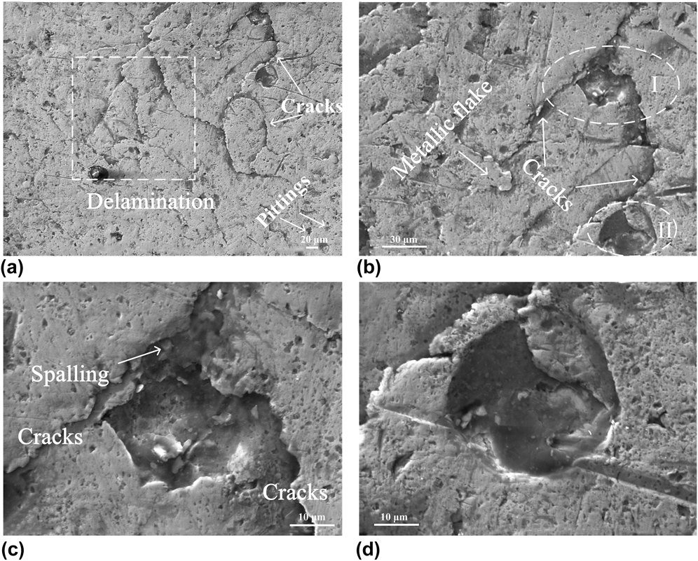
Different types of defects were visible on the worn surface, caused by a variety of factors. In Fig. 14(a), delamination, cracks, and pitting were observed on the region with high roughness, as the dominant representation of rolling fatigue failure. Commonly, these types of damages were the typical result of crack propagation. Differently, with respect to the nonlinear propagation of cracks, closed and unclosed cracks were presented. Unclosed cracks indicated the interrupted propagation processing, and as a result, the material element in the semiclosed region was removed from the surface. The phenomenon was clearly observable in the micrograph under high magnification [Fig. 14(b)]. In addition, metallic flakes were also observable on the surface where metallic tongue occurred (see Ref. Reference Franklin, Weeda, Kapoor and Hiensch20), because the formed cracks at subsurface reached the surface at a specific angle. By the development of these metallic flakes, a gradient surface was subsequently appeared, named as “delamination.” As shown in Fig. 14(b), two forceful cracks encountered at Region I, making the region more brittle and apt to develop into a defect-prone region. As cycle progressed, the defect at the intersecting region fanned out and made a ragged bottom, resulting in the typical spalling [Fig. 14(c)]. In addition, an apparent altitude intercept was revealed at the both side of semiclosed crack, in which the inside area of the crack was visibly lower than the outside one. This implied that the large sections of metal had been removed from the sample's surface, as a performance of the formation of typical delamination. In Region II, a crack branched from the major crack took circular form and prevented further damage by circular pitting [Fig. 14(b)]. Differently, circular pitting resulted from the propagation of a single crack was characterized by a flat bottom under high magnification [Fig. 14(d)]. So far, the reasons of cracks propagating in various paths had not been reported, and the authors conjectured that it was significantly affected by the stress intensity factor of crack.
The surface damages on the region with high surface toughness.
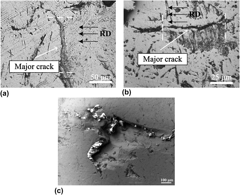
As far as relevant formation mechanisms, the fanned-out defect was caused by the interaction of two forceful cracks, while the circular defect was a result of the nonlinear propagation of a single crack. However, by the reduction of surface toughness, a completely different mechanism was responsible for the surface damage formation. As illustrated, the propagated direction of primary cracks were perpendicular [Fig. 15(a)] and parallel [Fig. 15(b)] to the rolling direction, respectively. The common continuous metal removal occurred along the one side of cracks during the processing of linear propagation (marked by the white dash lines in figures), which made the cracks look broader. To find out the details of the defect, a high-resolution defect was indicated in Fig. 15(c). As shown, this defect was characterized by an extended bottom to the contact surface from the bottom of the major crack at a certain angle. The result was in accordance with the found under lubricated condition in previous research, in which the initial crack was first directed toward the depth at an inclination of about 20°; when I branch > 1, a branch began to rise toward the contact surface inclined by about 90°, causing metal removal (see Ref. Reference Donzella, Faccoli, Ghidini, Mazzù and Roberti21). It should be noted that the type of defect was only observed during linear crack propagation. In contrast, during nonlinear propagation processing, it was caused in response to the damages as shown in Fig. 14. The exact mechanism at work during this process was not fully distinguishable, but will be examined further in our future research.
The surface damages on the region with low surface toughness.
IV. CONCLUSIONS
The most notable conclusions of this study can be summarized as follows.
In comparison with the region deposited by LM, the region treated by LC had finer, more compact and uniform crystals, though phase compositions were similar. LC-treated samples showed not only significantly improved micro-hardness, but also markedly enhanced tensile and compressive resistance. The degrees of improved mechanical properties were reduced in inverse proportion to the coating thickness. With respect to the distribution of contact stress, the unit portion was subjected to the highest contact stress which resulted in the reduction of the contact stress arisen on substrate, prolonging the substrate's fatigue life. No noticeable defects were apparent in the unit region. LC treatment had more positive effect on FWR improvement compared to LM treatment, and the degree of improvement increased with decreasing precoating thickness.
Two types of defect were observed: one was caused by nonlinear propagation of cracks, which presented flat bottom and cliff edges; the other was adjoined the major crack in the stage of linear propagation, in which the bottom connected to the surface at mild inclination from the bottom of the main crack.
ACKNOWLEDGMENTS
This article was supported by Project 985—High Performance Materials of Jilin University and the Project 985—Bionic Engineering Science and Technology Innovation and National Natural Science Foundation of China (No. 51275200).