I. INTRODUCTION
The transition-metal nitride coating of TiN has previously been applied in the surface modification of cutting tools to increase wear performance and service life Reference Vaz, Machado, Rebouta, Cerqueira, Goudeau, Riviere, Alvesc, Pischowd and de Rijkd1 because of its high hardness and high abrasion resistance. However, the working temperature of oxidation resistance is only 550 °C, Reference Niu, Li, Wang, Chen and Xue2 which can hardly meet the cutting requirements of hard machining materials. Reference Thakur and Gangopadhyay3 For further improving the wear performance of TiN coating, Al atoms are added into the TiN coating to form TiAlN coating, which improves the hardness and wear resistance. The mechanical and tribological performances of TiN coating have been increased, Reference AL-Bukhaiti, Al-hatab, Tillmann, Hoffmann and Sprute4 which satisfy the ever-growing demands of modern industrial applications. Reference Feng, Hu, Jiang, Wu, Li, Xin, Zhu and Wang5 TiAlN coating can be deposited using a chemical vapor deposition (CVD), cathode arc ion plating (CAIP), and reactive magnetron sputtering (RMP), Reference Li, Chen, Zou, Ma, Li and Li6 among them, the CAIP is widely used as a hard coating deposition technique because it has many advantages such as high deposition rate and strong bonding strength between the coating and the substrate. Reference Chang, Lin and Huang7 The TiAlN coating on cutting tools is demonstrated to have excellent high-temperature stability, Reference Wang, Li, Wang, Hu and Wu8 mechanical properties, Reference Zou, Zhang, Xie, Shao and Fu9 and wear resistance, Reference Liu, Deng and Tao10 which has been attracted many attentions in China and abroad. The addition of Al atoms into the FCC (face centered cubic) structure of TiN coating forms a TiAlN coating, the grain refinement of the TiAlN coating improves its hardness, high temperature oxidation, and wear resistance. Reference Keunecke, Stein, Bewilogua, Koelker, Kassel and van den Berg11 The presence of Al in the TiAlN coating overcomes the oxidation problems due to a superficial layer of Al2O3 formed at high temperature, which restricts oxygen diffusion and oxidative wear. Reference Tomaszewski, Gulbinski, Urbanowicz, Suszko, Lewandowski and Gulbinski12 The researches focus on mainly studying the deposition methods, growth mechanisms, and mechanical performances of the TiAlN coating. Reference Kong and Fu13 At present, the research works had been done on cutting performance and service life of the TiAlN coating on cutting tools. Reference Long, Zeng, Yu and Wu14 To date, the energy spectrum analysis and wear mechanism of the TiAlN coating have been rarely investigated. In this study, a TiAlN coating was deposited on YT14 cemented carbide cutting tools with a CAIP, the surface–interface morphologies, distributions of chemical elements, phases, and microhardness were analyzed with a field emission scanning electronic microscope (FESEM), energy dispersive spectrometer (EDS), X-ray diffraction (XRD), and microhardness tester, respectively, and bonding strength of the coating interface was characterized with a scratch tester. In addition, the friction–wear characteristics of the coating were investigated by using a multifunctional material surface tester which provided an experimental basis for evaluating the surface application in cutting tools.
II. EXPERIMENTAL
The experimental substrate was commercial YT14 cemented carbide cutting tools, which composed of TiC, WC, and Co as a binder; the chemical compositions were shown as follows (wt/%): WC 78, TiC 14, Co 8. Before being deposited, the samples were ground by the sandpapers of 80#–1200#, metallographic sandpaper, and polishing on a P-2T type polishing machine in turn (Guangzhou Weiyi Metallographic Test Instrument Co., Ltd., Guangzhou, China). Moreover, the samples were cleaned in pure acetone using ultrasonic oscillation, rinsed in pure ethanol, and dried up before being deposited in a PVT (plasmaund vakuum technik gmbh) coating system. The working gas was Ar with a high purity of 99.99%, and reaction gas was N2 with a high purity of 99.99%, the target was a Ti–Al alloy target with an atom fraction rate of 1:1. Before being deposited, the alloy target was etched with ions for 30 min to remove the organic adhesion complexes and oxidation layer of the target surface. The deposition parameters are shown in Table I. The surface–interface morphologies and chemical compositions of the obtained TiAlN coating were analyzed with a JSUPRA55 type FESEM (Carl Zeiss AG, Oberkochen, Germany), and its configured EDS, respectively, the phases of the coating were analyzed with a 2500PC type XRD (Rigaku Corporation, Tokyo, Japan), and the coating topography and grain scales were analyzed with a CSPM5500 type atomic force microscope (AFM; Original Nano-Instrument Co. Ltd., Beijing, China). The bonding strength of the coating interface was measured with a WS-2005 type film scratch tester (Lanzhou Zhongkai Science and Technology Development Co. Ltd., Lanzhou, China), the measurement method was acoustic emission, test parameters: load of 100 N, loading rate of 50 N/min, and scratch length of 4 mm. The microhardness of the coating was measured with a HV-1000 type micro-Vivtorinox hardness tester (Guangzhou Weiyi Metallographic Test Instrument Co. Ltd., Guangzhou, China), test parameters: load of 0.2 N, time of 15 s, the coating microhardness was presented with the average value in five times measurement. The friction and wear performances of the coating were investigated with a CFT type multifunctional material surface tester (Lanzhou Zhongkai Science and Technology Development Co. Ltd., Lanzhou, China), test parameters: load of 5 N, test time of 30 min, friction mode: sliding, friction pair: ceramic ball (Si3N4) with a diameter of 4 mm, running speed of 500 times/min, and running length of 3 mm.
Deposition parameters of TiAlN coating.

III. ANALYSIS AND DISCUSSION OF RESULTS
A. Surface–interface morphologies
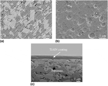
Figure 1(a) shows the surface morphology of a YT14 cemented carbide cutting tool after grinding. The visible WC and TIC particles were distributed in the binder Co, which remained the high hardness for the substrate. The surface roughness was ∼0.1 μm measured with a TR240 type surface roughness tester (Beijing Times Technology Co. Ltd., Beijing, China).
Morphologies of a YT14 cemented carbide cutting tool surface and TiAlN coating surface–interface: (a) substrate morphology; (b) coating surface morphology; (c) coating interface morphology.

The obtained TiAlN coating was continuously and uniformly distributed, as shown in Fig. 1(b). There was no particle spallation, this was because CAIP was accompanied by the emission of particles when the plasma was produced with high energy at the high density state. The coating thickness was ∼1.5 μm, as shown in Fig. 1(c), the coating structures at the bonding interface were compact and were closely combined with the substrate.
B. EDS and XRD analysis
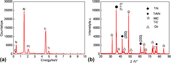
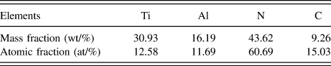
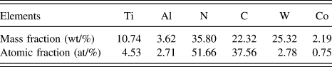
The EDS analysis result of TiAlN coating is shown in Fig. 2(a), and the mass fractions and atomic fractions are shown in Table II. The TiAlN coating was primarily composed of Ti, Al, and N, in addition, the appeared C element came from the contaminated products in the air. The mass fraction ratio of Ti/Al in the coating was close to 2:1, compared with the Ti and Al elements in the alloy targets, the mass fraction ratio of Ti and Al was 1:1, which was increased. The low Al content improved lattice distortion structure defects in the coatings and caused the lattice distortion for a constant lattice increase, which decreased the coating roughness Reference Zou, Zhang, Xie, Shao, Guo and Fu15 and changed the crystal preferred orientation of the coating growth, Reference Escobar-Alarcón, Solís-Casados, Romero, Fernández, Pérez-Álvarez and Haro-Poniatowski16 this was due to the difference of resputtering rate of Ti and Al atoms.
EDS and XRD analysis of TiAlN coating: (a) EDS analysis; (b) XRD analysis.

EDS analysis result of TiAlN coating.

The phase result of the TiAlN coating was measured by an XRD analysis with a Cu Kα1 radiation (λ = 1.54056 Ǻ), as shown in Fig. 2(b), the diffraction peaks of TiAlN (ICDD card no. 71-5864) at the diffraction angle of 37° and TiN (ICDD card no. 06-0642) Reference Matei, Pencea, Branzei, Trancă, Ţepeş, Sfăt, Ciovica (Coman), Gherghilescu and Stanciu17 at the diffraction angles of 44 and 63° were detected, respectively. For the TiN phase, the TiN energies of crystal planes (200) and (220) were minimized, therefore, the preferential growth of TiN was along crystal planes (200) and (220), and the microstructure of the coating was the TiN phase. When the Al was added to the TiN to replace the part of Ti, the diffraction peak shifted to a low angle, the spacing of crystal planes became large. The TiAlN coating was preferred to grow in the crystal plane (111), the lattice structure was still FCC structure. Reference Kong and Fu13 Because the thickness of the TiAlN coating was very thin, the substrate peaks of WC (ICDD card no. 51-0939), TiC (ICDD card no 32–1383), and Co (ICDD card no 15-0806) Reference Matei, Pencea, Branzei, Trancă, Ţepeş, Sfăt, Ciovica (Coman), Gherghilescu and Stanciu17 were detected by X-ray.
C. AFM analysis
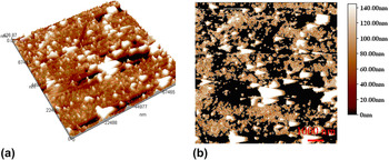
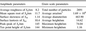
Figure 3 shows the AFM topography and grain scale of the TiAlN coating using the AFM configured imager 4.60 software, the corresponding amplitude and gain scale parameters are shown in Table III. The amplitude parameters were small, as shown in Fig. 3(a), the coating surface fluctuated a little, showing that the surface quality of the TiAlN coating had a well friction performance. The grain scales on the TiAlN coating with a smooth process are shown in Fig. 3(b), the total grain number of the TiAlN coating was 2691, the corresponding average area, diameter, and height was 1.69 × 10⁶ nm2, 463.9 nm, and 14.62 nm, respectively. According to the Hall–Petch equation, Reference Long, Zeng, Yu and Wu14 the smaller the particle size was, the higher the material hardness was. As a result, the TiAlN coating had high microhardness due to fined grains, which was 2724 HV measured by five times on a HV-1000 micro-Vivtorinox hardness tester. Compared with 2150 HV of TiN coating, Reference Quesada, Mariño and Restrepo18 the microhardness of TiAlN coating was increased by about 27%. This was because that the addition of Al in the coating formed TiAlN coating with the low content of Al, which not only had an effect of solid solution hardening but also changed the coating microstructure and crystallographic orientation.
AFM topography and particle distribution of TiAlN coating surface: (a) AFM topography; (b) particle distribution.

Roughness parameters and grain size parameters of TiAlN coating.

D. Energy spectrum analysis of surface and interface
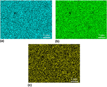
The chemical element distributions of the coating in Fig. 1(b) were analyzed with a plane scan analysis, Ti, Al, N, and C were detected, among them, C was the contaminated products on the TiAlN coating in the air. There were black spots existed on the plane energy spectrum of Ti, Al, and N elements, which was because that the ions bombarded the coating surface, the resputtering effect caused the pores during the deposition, resulting in uneven local distribution of Ti, Al, and N elements, as shown in Fig. 4(a)–4(c).
Plane scans of TiAlN coating surface: (a) Ti content; (b) Al content; (c) N content.

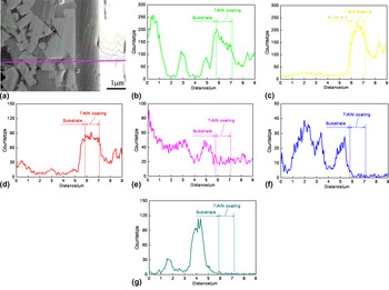
Figure 5(a) shows the line scanned position of the coating interface. Ti, Al, and N of the coating interface presented a gradient distribution; the contents of chemical elements in the coating were gradually reduced, as shown in Figs. 5(b)–5(d). Ti, Al, and N were diffused at the interface, which improved the bonding state between the coating and the substrate. This was because that at the initial stage of deposition, the coating was covered on the substrate. The C content in the substrate was high, as shown in Fig. 5(e), this was because that the hard carbide cutting tool was primarily composed of WC and TiC. Reference Kalinn and Jerina19 W and Co in the substrate did not produce a diffusion phenomenon, as shown in Figs. 5(f)–5(g).
Line scan analysis of TiAlN coating interface: (a) line scanned position; (b) Ti content; (c) Al content; (d) N content; (e) C content; (f) W content; (g) Co content.

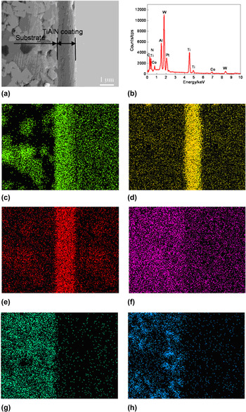
Figure 6(a) shows the position of the plane scan analysis at the coating interface, the result of the plane scan analysis is shown in Fig. 6(b), and the corresponding data are shown in Table IV. Ti, Al, and N formed a gradient diffusion layer at the interface, and there was a small amount of elements penetrating into the substrate, as shown in Figs. 6(c)–6(e). The boundary of the coating–substrate interface was obvious, and there was a stratification phenomenon, which was mechanical combination. The C distribution is shown in Fig. 6(f), coming from the substrate. As shown in Figs. 6(g)–6(h), the W and Co elements were distributed in the substrate, there was no diffusion. Therefore, the interface of the TiAlN coating was mechanical bonding, accompanied with local metallurgical bonding.
Plane scans of TiAlN coating interface: (a) plane scanned position; (b) result of plane scan analysis; (c) Ti content; (d) Al content; (e) N content; (f) C content; (g) W content; (h) Co content.

Plane scan analysis result of TiAlN coating interface.

E. Interface bonding strength
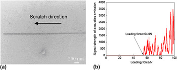
The diamond head with a radius of 0.2 mm was used to scratch on the TiAlN coating surface, when the load gradually increased to a certain value, there was break-off phenomenon that appeared between the coating and the substrate, Reference Liu, Deng and Tao20 as shown in Fig. 7(a). At the point, the critical load was the bonding strength of the coating interface, showing that the binding strength of the TiAlN coating was 54.9 N, as shown in Fig. 7(b).
Scratch morphology and bonding strength of TiAlN coating: (a) scratch morphology; (b) binding strength.

F. Friction and wear performance
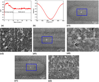
Figure 8(a) shows the relationship between COFs and wear time, the average COF was 0.59, of which the uncertainty was decided by the coating surface roughness and measurement errors. Reference Kong and Guo21 In the running-in period (0–10 min), the COF was increased rapidly with large fluctuation. This was because that the particles and pits of the coating surface made the friction resistance increase sharply, and the average COF was 0.56. The COF was gradually reduced with the wear time increasing. This was because the surface of the TiAlN coating was constantly polished. At the stable period (10–30 min), the average COF was 0.44, the TiAlN coating had high wear resistance. Reference Liu, Deng, Cui, Chen and Zhao22 The wear volume of the TiAlN coating is shown in Fig. 8(b), the selected surface baseline was −1.335 μm, the width and depth of wear profile were 318 μm, 2.335 μm, respectively, and the wear rate was 1.73 × 10⁻⁵ mm3/N m, which indicated that the coating had high wear resistance.
COFs and wear profile of TiAlN coating: (a) COFs versus wear time; (b) wear profile; (c) initiating zone; (d) central zone; (e) ended zone.

After the wear test, the TiAlN coating surface was covered with a layer of debris, the number of wear debris at the initiating and terminal ends was the most, there were some obvious thin furrows, as shown in Fig. 8(c). This was due to the friction effect of wear debris on the coating, there were some obvious wear phenomena. In the wear process, the cracks occurred, which caused larger wear debris. It verified that large particles of the coating surface occurred brittle fracture under the action of reciprocating friction, Reference Ramadoss, Kumar, Pandian, Dash, Ravindran, Arivuoli and Tyagi23 as shown in Fig. 8(d). In the course of friction, the wear debris at the worn scar edges were continuously removed, so the chip removal capacity was strong. Reference Sveen, Andersson, Saoubi and Olsson24 As shown in Fig. 8(e), the wear mechanism of the TiAlN coating was abrasive wear, accompanied by slight brittle fracture.
IV. CONCLUSIONS
-
(1) The TiAlN coating with a microhardness of 2724 HV is composed of TiN and TiAlN phases.
-
(2) Ti, Al, and N are combined with mechanical bonding at the interface, accompanied with locally metallurgical bonding, the interface bonding strength is 54.9 N.
-
(3) The average COF of TiAlN coating is 0.59, and the wear mechanism is abrasive wear + slight brittle fracture, showing deducing friction and wear resistance.
ACKNOWLEDGMENTS
Financial support for this research by the Jiangsu Province Science and Technology Support Program (Industry) (BE2014818) is gratefully acknowledged.