I. INTRODUCTION
Polyaniline (PANI) is unique in the family of conjugated polymers since it has rich redox chemistry and a simple and reversible acid doping/base dedoping process,Reference Salaneck, Lundstrom, Hjertberg, Duke, Conwell, Paton, Macdiarmid, Somasiri, Huang and Richter1 which enables control over properties such as free volume,Reference Anderson, Mattes, Reiss and Kaner2 solubility,Reference Cao, Smith and Heeger3 electrical conductivity,Reference Chiang and MacDiarmid4 and chemical/biological sensitivity.Reference MacDiarmid5 Nanostructured PANI, especially nanorods, nanowires, and nanofibers, offers the possibility of enhanced performance with a high interfacial area between PANI and its environment. As sensors, these electrically conductive nanostructures have greater sensitivity and faster response time relative to its conventional bulk counterpart due to their higher effective surface areas. However, a simple and effective process for preparing these nanostructures with desired characteristics in their composites remains a scientific challenge, and this is the issue that will be addressed in this article.
Generally, the chemical synthesis of PANI uses aniline, an oxidant, and a strong mineral acid dopant.Reference Salaneck, Lundstrom, Hjertberg, Duke, Conwell, Paton, Macdiarmid, Somasiri, Huang and Richter1 PANI nanotubes or nanofibers can be prepared by template-guided polymerization within channels of nanoporous membranesReference Wang, Wang, Li and Li6 or zeolites.Reference Wang, Wang, Li and Li6, Reference Wu and Bein7 Adding structure-directing agents, such as a surfactantReference Qiu, Wan, Matthews and Dai8 or a comonomer,Reference Yang, Chih, Cheng and Chen9 to the chemical polymerization bath is an alternative way to yield PANI nanostructures.Reference Qiu, Wan, Matthews and Dai8, Reference Yang, Chih, Cheng and Chen9 When organic dopants having surfactant functionalities are used, micelle formation leads to micro- or nanostructures, such as fibers, rods, or nanothin films.Reference Wei, Zhang and Wan10, Reference Yang, Chih, Huang and Chung11 Despite the variety of synthetic approaches to PANI nanostructures, there is still a need for a practical synthetic method capable of making pure, uniform, and template-free PANI nanostructures in bulk quantities, which are useful for the properties that depend on their ultrasmall and low-dimensional structures.
Recently, an interfacial polymerization route has been successfully developed by Kaner for the synthesis of polyaniline nanofibers (PANFs) with a diameter <100 nm without using a template.Reference Huang and Kaner12 However, these nanostructured materials are brittle, which limits their practical use. One approach for improving their mechanical properties is to blend them with conventional polymers.Reference Hopkins and Reynolds13, Reference Mirmohseni and Wallace14 Although many polymers have been used as host matrices in these blends, the maintenance of the originally highly electroactivity of the PANI nanostructures remains a formidable challenge.
We postulated that poly(vinyl alcohol) (PVA) should be an excellent host material because it is a water soluble, good film-forming, firm, nontoxic, and biocompatible polymer. Hence, PVA-modified electrodes were expected to be extensively applied for the electrochemical detection.Reference Tsai, Huang and Chiu15–Reference Li and Lin17 In this work, the PANFs prepared by the interfacial polymerization route were blended with PVA to form electroactive nanocomposites. We found that the presence of PVA in PANF suspension can prevent the aggregation of PANF and enhance the casting film quality. When 25 wt% PVA is added to PANF–PVA suspension (PANF‑PVA25), the composite film (casting at 105 °C) shows a porous nanostructure and possesses the excellent electroactivity and electroactive stability. However, we found that thermal treatment with PANF–PVA25 (casting at 200 °C) will cause the formation of ether linkage between PANF and PVA polymer chain, resulting in a decrease in the electroactivity and electroactive stability. Hence, we conclude that the thermal treatment with PANI–PVA is unfavorable for electrochemical applications of the nanocomposite.
II. MATERIALS AND METHODS
A. Reagents and materials
Chloroform (Mallinckrodt Chemicals, St. Louis, MO), ammonium persulfate (Baker, Phillipsburg, NJ), and hydrochloric acid (Riedel-de Haën, St. Louis, MO) were all of analytical grade and used as received. Aniline (Riedel-de Haën, St. Louis, MO) was distilled under a reduced pressure and stored at low temperature in the dark prior to use. Fully hydrolyzed (>99%) PVA (M w = 89,000–98,000 g mol−1) was obtained from Sigma-Aldrich (St. Louis, MO). Aqueous solutions were prepared using double distilled water.
B. Preparation of PANF
PANFs were synthesized via the interfacial polymerization according to literature procedures.Reference Huang and Kaner12 For a typical synthesis, 30 mmol of aniline dissolved in 100 mL of chloroform and 7.5 mmol of ammonium persulfate dissolved in 100 mL of 1 M HCl were transferred to a beaker. Due to the immiscible properties of chloroform and water, there were two layers in the beaker. After reacting at room temperature for 24 h, the entire water phase was filled homogeneously with dark-green PANI, and this phase was then collected and purified by dialysis (dialysis tubing, 8000 MW cut off). The precipitated polymer nanofibers were thoroughly washed with water and vacuum dried for 24 h at room temperature.
C. Preparation of PANF–PVA nanocomposites
PANF–PVA binaries with various compositions were prepared by mixing various amounts (0–7.5 g L−1) of PVA with a fixed amount (2.5 g L−1) of PANF in water, according to the following procedure. First, PVA was fully dissolved in water at 90 °C and was, then, cooled to room temperature. Subsequently, 0.25 g of PANF was added to 100 mL aqueous solution with various amount of PVA. The system was then sonicated until well-dispersed PANF suspensions were obtained. The suspensions were cast on a Teflon plate or the indium-doped tin oxide (ITO) glass substrate, followed by removing the residual water at 105 or 200 °C for 30 min to afford the composite films. For convenience, PANF–PVA nanocomposites, which contain 25, 50, and 75 wt% PVA, are designated as PANF–PVA25, PANF–PVA50, and PANF–PVA75, respectively.
D. Characterization of PANF–PVA nanocomposites
The microstructure was examined using scanning electron microscope (SEM; Philips XL-40 FEG, Amsterdam, Netherlands). The conductivity of dry samples compressed to compact pellets was measured using the standard four-point technique (ELCHEMA model CM-308, Potsdam, NY). The molecular structures were characterized by Fourier transform infrared (FTIR; Nicolet 550 spectrometer, Madison, WI) spectroscopy employing KBr pellet technique. Thermogravimetric analysis (TGA) was performed on a Perkin-Elmer TGA 7/DX thermal analyzer (Waltham, MA) over a temperature range of 100–900 °C in a nitrogen atmosphere at a heating rate of 10 °C min−1. Electrochemical analysis was performed using a PGSTAT20 electrochemical analyzer (AUTOLAB, Eco. Chemie B. V., Utrecht, Netherlands). A platinum wire and Ag/AgCl (in 3 M KCl) were used as the counter and reference electrodes, respectively, while PANF–PVA binaries cast on ITO was used as the working electrode. A Luggin capillary, whose tip was set at a distance of 1–2 mm from the surface of the working electrode, was used to minimize errors due to iR drop in the electrolytes.
III. RESULTS AND DISCUSSION
A. The suspension stability of PANF
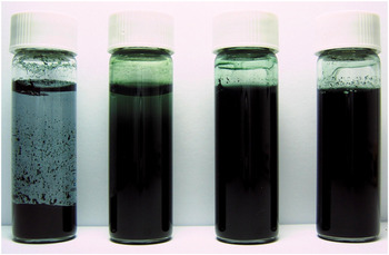
Figure 1 shows the suspension stability of 2.5 g L−1 PANF in aqueous solution in the presence of various amounts of PVA. PANF aggregated and precipitated visibly 3 days after the preparation, indicating the poor stability of PANF in aqueous solution. The suspension stability of PANF was significantly enhanced from few days to 3 months by adding a small amount of PVA (0.83 g L−1). As the amount of PVA (2.5‑7.5 g L−1) became larger than that of PANF, the suspensions remained stable without precipitation for more than 3 months. Hence, the addition of PVA significantly increases the stability of PANF suspension. Such an enhancement is expected to form a more uniform PANF–PVA film on a substrate in comparison with the PANF film.
Photograph of 2.5 g L−1 polyaniline nanofiber (PANF) suspensions in (a) 0 g L−1, (b) 0.83 g L−1, (c) 2.5 g L−1, and (d) 7.5 g L−1 polyvinyl alcohol (PVA) solutions taken after as prepared (a) 3 days later and (b, c, and d) 3 months later.

B. Morphology
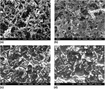
The surface morphology and microstructure of the various PANF‑PVA nanocomposites cast on ITO were examined by SEM. As shown in Fig. 2, PANF shows the fibrillar structure with an average diameter of approximately 70 nm and lengths from 500 nm up to several micrometers. These fibers aggregate side-by-side and stack together to form a porous structure. With the addition of a small amount of PVA (PANF–PVA25), these porous structures can still be seen and the fiber diameters increase to approximately 130 nm. The boundary of each single PANF becomes indistinct because the PANF was covered by a thin PVA film. In this case, the aggregation of PANF is prevented by PVA. As the amount of PVA was increased to 50 wt%, the porous structures almost disappeared because of the filling of PVA into the pores of PANF networks. When the amount of PVA was further increased to 75 wt%, PANF was almost buried in the PVA and the PANF–PVA nanocomposite was not porous, but had a bulk film structure.
Scanning electron microscopic images of (a) PANF, (b) PANF–PVA25, (c) PANF–PVA50, and (d) PANF–PVA75 nanocomposites cast on indium-doped tin oxide substrate.

C. Conductivity
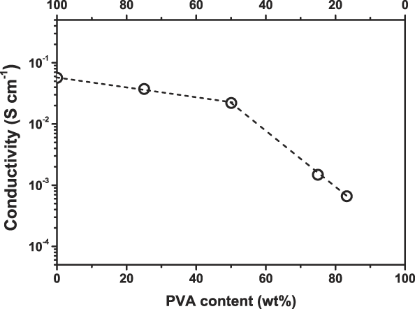
Figure 3 shows the conductivity of the various PANF–PVA nanocomposites. The conductivity decreases as the amount of PVA increased because PVA is not a conducting polymer. There are two stages for the decreasing trend of conductivity in these PANF–PVA nanocomposites. In the first stage, where the amount of PVA is less than 50 wt%, the conductivity of the PANF–PVA only decreases slightly. The conductivity was found to be 5.7 × 10⁻², 3.7 × 10⁻², and 2.2 × 10⁻² S cm−1 for 0, 25, and 50 wt% PVA, respectively. In the second stage, where PVA is more than 50 wt%, the decrease of conductivity is as high as two orders of magnitude, which is 2.2 × 10⁻² and 6.7 × 10⁻⁴ S cm−1 for 50 and 83.3 wt% PVA, respectively. The above results suggest that the PANF–PVA nanocomposites in the first stage are suitable for applications that require good conductivity.
The conductivity trend for various PANF–PVA nanocomposites.

D. Thermal analysis
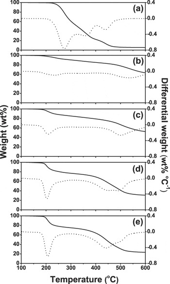
The thermal analysis is further investigated by TGA. The TGA and differential thermal analysis (DTA) curves of PVA, PANF, and PANF–PVA nanocomposites are shown in Fig. 4. For PVA [Fig. 4(a)], no weight loss is observed at 210 °C. Major weight loss at 270 °C arises from dehydration of vinyl alcohol segments to form the unsaturated structure (polyenes) and the cross-linked structure. The second and third weight losses correspond to the degradation of unsaturated structure at 370 °C and cross-linked structure at 440 °C, respectively, resulting in both cases to the evolution of some hydrocarbons as volatile products.Reference Ghosh, Siddhanta, Haque and Chakrabarti18 For PANF [Fig. 4(b)], the first weight loss takes place at 240 °C, being attributed to the release of the dopant (HCl). The major weight loss at 540 °C, corresponding to significant thermal degradation of PANF polymer chains.Reference Ghosh, Siddhanta and Chakrabarti19 For PANF–PVA nanocomposites [Fig. 4(c)‑4(e)], the start temperature of the first weight losses at 170 °C is the same as that for PANF and the weight loss also increases with increasing PVA, indicating the acid-catalytic dehydration of PVA for the formation of cross-linked PVA. The second and third weight losses can be attributed to the degradation of cross-linked PVA at 440 °C and PANF polymer chains at 500 °C, respectively. The weight losses of PANF degradation shift from 540 °C for PANF to 500 °C for PANF–PVA nanocomposites, indicating that an interaction or chemical bonding between the interface of PANF and PVA causes the decrease in thermal stability of PANF. Moreover, these results also indicated that the mechanical strength of PANF–PVA nanocomposites may be improved by setting the different drying temperatures because PVA will cross-link as the temperature is higher than 200 °C.
Thermogravimetric analysis (—) and differential thermal analysis (…) curves of (a) PVA, (b) PANF, (c) PANF–PVA25, (d) PANF–PVA50, and (e) PANF–PVA75 nanocomposites.

E. FTIR analysis
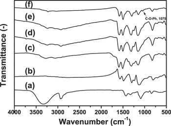
Because the suspension stability, film quality, microstructure, and conductivity are strongly dependent on the PVA content in PANF–PVA nanocomposites, the interaction between PANF and PVA is interesting to be clarified and is investigated by FTIR spectrometer. Figure 5 shows the FTIR spectra of PVA, PANF, and PANF–PVA nanocomposites. For PVA (curve a), a broad band at 3400–3100 cm−1 due to O–H stretching vibration and the band at 2930 and 1147 cm−1 assigned as C–H and C–O stretching vibration are observed, respectively. For PANF (curve b), the band at 1301 cm−1 is due to C–N stretching vibration and the bands at 1564 and 1483 cm−1 are assigned as the stretching vibration of quinoid and benzenoid rings, respectively. For PANF–PVA nanocomposites (curve c–e) casting at 105 °C, the characteristic bands of both PANF and PVA are observed and their absorption intensities increase with their own contents. However, their C–O and C–N stretching vibration bands shift to a higher wave number. These demonstrated the formation of hydrogen bonding between hydroxyl groups of PVA and nitrogen sites of PANF, leading to the prevention of PANF aggregation and the improvement of film quality.
Fourier transform infrared spectroscopy spectra of (a) PVA, (b) PANF, (c) PANF–PVA25, (d) PANF–PVA50, and (e) PANF–PVA75 nanocomposites casting at 105 °C and (f) PANF–PVA25 nanocomposite casting at 200 °C.

The thermal effect on the interaction or chemical bonding between the interface of PANF and PVA is also important for further application of PANF–PVA nanocomposites. Compared with that of PANF–PVA25 casting at 105 °C (curve c), the FTIR spectrum of PANF–PVA25 casting at 200 °C (curve f) shows a decrease in intensity of O–H stretching band, being attributed to the cross-linking of hydroxyl groups of PVA polymer chain. The formation of a new band at 1075 cm−1 is also observed in the FTIR spectrum of PANF–PVA25 casting at 200 °C due to the absorptions of C–O and Ph–O stretching vibrations in alkyl C–O–Ph,Reference Chen and Fang20 and the intensity of quinoid ring band decreases. These results indicate that the formation of the ether linkage between PANF and PVA accompanies the conversion of quinoid rings to bezenoid rings as PANF–PVA nanocomposites casting at 200 °C.
F. Electroactivity and electroactive stability
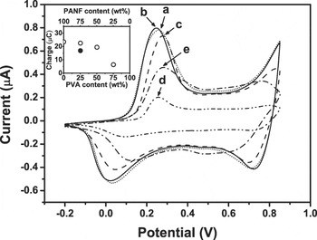
PANI was widely used for the electrochemical applications due to its interesting redox and electrocatalytic behavior, and meanwhile electroactivity and electroactive stability are the important properties. The electroactivity of PANI-contained electrodes can be evaluated by the redox peaks potential and the redox charge of cyclic voltammograms (CVs). Figure 6 shows the first cycle of CVs in 0.5 M H2SO4 solution for PANF and PANF–PVA nanocomposites modified electrodes casting at 105 °C. The PANF electrode (curve a) exhibits two well-defined redox peaks at approximately 0.232 and 0.840 V, which are attributed to the redox processes of lecuoermeraldine/emeraldine and emeraldine/pernigraniline, respectively. The unobvious redox peaks at approximately 0.520 V are attributed to the process of quinone/hydroquinone produced by the degradation of PANI at high potential. For PANF‑PVA25 (curve b), the first redox peak potential shifts from 0.232 to 0.227 V. This negative shift can be attributed to the prevention of the PANF aggregation by PVA, leading to a decrease in the diffusion resistance of dopant. For PANF–PVA50 and PANF–PVA75 (curve c and d), the first redox peaks shift to a higher potential, which are more than 0.250 V. These results indicate that more PVA addition will increase the diffusion resistance of dopant due to the nonconducting properties of PVA.
The first cycle of cyclic voltammograms (CVs) for (a) PANF, (b) PANF–PVA25, (c) PANF–PVA50, and (d) PANF–PVA75 modified electrodes casting at 105 °C and (e) PANF–PVA25 modified electrode casting at 200 °C in 0.5 M H2SO4 solution at a scan rate of 25 mV s−1. Inset: the trend of the redox charge in PANF–PVA nanocomposites.

The CVs are further integrated to obtain the redox charge for the evaluation of electroactivity. The trend of the redox charge of the electrodes is shown in the inset of Fig. 6. The redox charge of the electrodes decreases with increasing the PVA contents, indicating a decrease in the conductivity of the electrodes. It is attributed to the fact that the partial PANFs are surrounded completely by PVA thus loses the redox ability. With increasing PVA more than 50 wt%, most parts of PANF loss the redox ability because they are buried in PVA matrix.
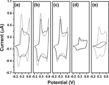
The redox charge of a conducting polymer always decreases with increasing the scanning cycles of cyclic voltammetry (CV) because of its degradation at high potential. The electroactive stability for PANF and PANF‑PVA nanocomposites modified electrodes can be evaluated using relative decrease (RD) as a criterion, which can be calculated (Fig. 7) according to the following equation:

The 1st cycle (—) and 20th cycle (―) CVs for (a) PANF, (b) PANF–PVA25, (c) PANF–PVA50, and (d) PANF–PVA75 modified electrodes casting at 105 °C and (e) PANF–PVA25 modified electrode casting at 200 °C in 0.5 M H2SO4 solution at a scan rate of 25 mV s−1.

where Q 1 and Q 20 are the redox charges at the 1st and 20th cycles, respectively. From this equation, the higher RD means the poor stability of the electrode. The RD values of PANF, PANF–PVA25, PANF–PVA50, and PANF–PVA75 modified electrodes are 30.2, 5.8, 2.4, and 1.8, respectively. It is interesting that adding only a small amount of PVA in PANF–PVA nanocomposites can significantly decrease the RD values. With increasing the PVA contents in PANF–PVA nanocomposites, the RD value only decreases slightly. It means that only a small amount of PVA will greatly enhance the stability of PANF. Thus, it is conceivable that the interaction of hydrogen bonding has a positive influence on the electroactive stability of the PANF–PVA nanocomposites.
From the above results, it is expected that PANF–PVA25 can be used for electrode applications due to the relative high electroactivity and the better electroactive stability in 0.5 M H2SO4 solution. However, the thermal effect should be noticed for using PANF–PVA25 nanocomposite. The first cycle of CV in 0.5 M H2SO4 solution for PANF–PVA25 electrode casting at 200 °C was also shown in Fig. 6 (curve e), and its redox charge was shown in the inset of Fig. 6. The first redox peak potential of the PANF–PVA25 modified electrode casting at 200 °C shifts positively, and its redox charge decreases in comparison with the electrode casting at 105 °C. However, the quinone/hydroquinone redox peaks are almost same for the two electrodes. These results indicate that the decrease in electroactivity is not due to the thermal degradation of PANF. It is believed that the decrease in electroactivity can also be attributed to the ether linkage between the interface of PVA and PANF, which was discussed in FTIR results. The electroactive stability of PANF–PVA25 modified electrode casting at 200 °C was also evaluated, and the CVs were shown in Fig. 7(e). In comparison with the PANF–PVA25 modified electrode casting at 105 °C, the electrode casting at 200 °C shows a RD value of 84.2%. This shows that increasing the casting temperature to 200 °C does not benefit the electroactive stability of PANF–PVA25 nanocomposite. This result also indicates that the side grafting of PANF polymer chain and losing of hydrogen bonding between PANF and PVA cause the easy degradation of PANF. This is also consistent with the TGA results. Therefore, the PANF–PVA25 nanocomposite should be prevented to cast at high temperature for electrochemical applications.
IV. CONCLUSIONS
A highly electroactive and stable PANF–PVA nanocomposite was prepared by using PVA as stabilizer to prevent the aggregation of PANF. The 25 wt% PVA contained PANF–PVA composite film (PANF–PVA25) has a porous structure and high conductivity. The presence of hydrogen bonding interaction between PANF and PVA improves the electroactivity and electroactive stability of PANF–PVA25. For electrochemical applications, casting the PANF–PVA film at high temperature must be avoided, which will cause the formation of ether linkage between PANF and PVA polymer chain. This linkage decreases the electroactivity and electroactive stability of the PANF–PVA modified electrodes.
ACKNOWLEDGMENTS
The authors are grateful to Dr. L. M. Huang for his valuable comments and stimulating discussion. The financial support of this work by the National Science Council (NSC) of Taiwan, under grant number NSC 95-2221-E-006-409-MY3, is gratefully acknowledged. Y. Wei thanks National Cheng Kung University (NCKU) for a Visiting Chair Professor appointment as supported by the “NCKU Project for Promoting Academic Excellence and Developing World Class Research Centers” (HUA98-12-3-140).