I. INTRODUCTION
The wireless power transfer (WPT) based on the magnetic resonant coupling between two or more coils is a very promising technology to transfer electrical energy without wires [Reference Cruciani and Feliziani1–Reference Choi, Gu, Lee, Lee, Huh and Rim13]. For this technology to become widespread in the next future, it is necessary that the magnetic field generated in the environment by WPT systems must be compliant with:
-
• electric and magnetic field (EMF) safety standards for human exposure [14];
-
• electromagnetic compatibility (EMC) regulations to avoid disturbances with other electric and electronic apparatuses and devices [15].
The compliance with the EMF and EMC regulations is very important, especially for the applications that require high power transfer rate [Reference Chan, Jian and Tu16], such as inductive charging for electric vehicles (EVs), where the transferred power can be up to 22 kW [17]. For the aforementioned reasons, the mitigation of the magnetic field is of paramount importance.
Current regulation for automotive WPT systems imposes the operational frequency of 85 kHz [17]. At this frequency, the magnetic field reduction in the environment can mainly be obtained in two ways: by (passive) shielding techniques using conductive and/or magnetic material panels or adding one or more (active) coils [Reference Buccella, Feliziani and Fuina18–Reference Schulz, Plantz and Brush20]. However, the WPT system is an intentional source of magnetic field. Thus, any field reduction using improperly active or passive shields could dramatically reduce the performances of the WPT itself that becomes unable to transfer the nominal power to the load [Reference Cruciani and Feliziani1, Reference Campi, Cruciani and Feliziani2].
Several studies aimed to mitigate the magnetic field emitted by two planar coils for WPT applications have already been proposed. In [Reference Budhia, Covic and Boys11], some passive magnetic shield configurations have been compared to find the best solution in terms of coupling factor between the coils. In a previous study from the authors [Reference Campi, Cruciani, Maradei and Feliziani12], an optimization procedure of the magnetic shield has been proposed to reduce the emitted magnetic field, while in [Reference Choi, Gu, Lee, Lee, Huh and Rim13] a detailed study of the shielding techniques through active coils has been carried out. However, all these studies have focused their attention either on the WPT efficiency or on the magnetic field reduction.
In this study, both the reduction of the magnetic field in the desired zone and the influence of the shield on the electrical performances are taken into account. Those aspects are very important in automotive applications, where the magnetic field must be reduced without an excessive degradation of the system performances. To achieve these results, a passive shielding technique made by a combination of conductive and magnetic material panels has been investigated.
The considered WPT system is composed of two parallel coupled coils: the primary placed outside the EV on the road, while the secondary is located in the vehicle underbody in close proximity of many metallic objects as chassis, platform, engine, electrical wiring system, etc. The coupled coils are modeled by an equivalent two-port network whose circuit lumped parameters are depending not only on the configurations of the coils but also on the conductive and magnetic materials in the surrounding environment [Reference Cruciani and Feliziani1, Reference Campi, Cruciani and Feliziani2].
The magnetic field and the influence of the shields on the WPT efficiency are validated by measurements carried out in a simple WPT system demonstrator. Finally, several shield configurations using both magnetic and conductive material panels are proposed considering a real automotive WPT system. In this case, the presence of the conductive chassis of the vehicle is taken into account in order to find the best solution to mitigate the magnetic field created by the same WPT system while maintaining high efficiency. The obtained magnetic field levels for the optimized solution are then compared with EMF safety limits, i.e., the reference level (RL), provided by the ICNIRP guidelines [14]. Some discussions on the magnetic shielding in future EVs made of carbon-fiber panels are also outlined.
II. WPT SYSTEM SHIELDING
A) Conductive shielding
Shielding of magnetic near fields is a relevant problem for EMC engineers. It is well known that the use of metallic panels can be inadequate to mitigate the magnetic field at very low frequencies [Reference Cruciani and Feliziani1, Reference Campi, Cruciani and Feliziani2]. The magnetic shielding effectiveness (SE H ) for a time-harmonic field is defined as:
 $$SE_H = 20\log _{10}(H^i/H),$$
where H and Hi are the magnetic fields at the observation point in the presence and in absence of the shield, respectively.
Considering a one-dimensional problem as a plane wave impinging normally on an infinite shield panel, SE H for conductive shields can be approximated by [Reference Schulz, Plantz and Brush20]
 $$SE_H = A_{dB}(\omega ) + R_{dB}(\omega ) + M_{dB}(\omega ),$$
where ω is the angular frequency, A dB represents the absorption loss of the wave as it proceeds through the shield barrier, R dB represents the reflection loss caused by the field reflection on the shield surface, and M dB represents the additional effects of multiple reflections and transmissions.
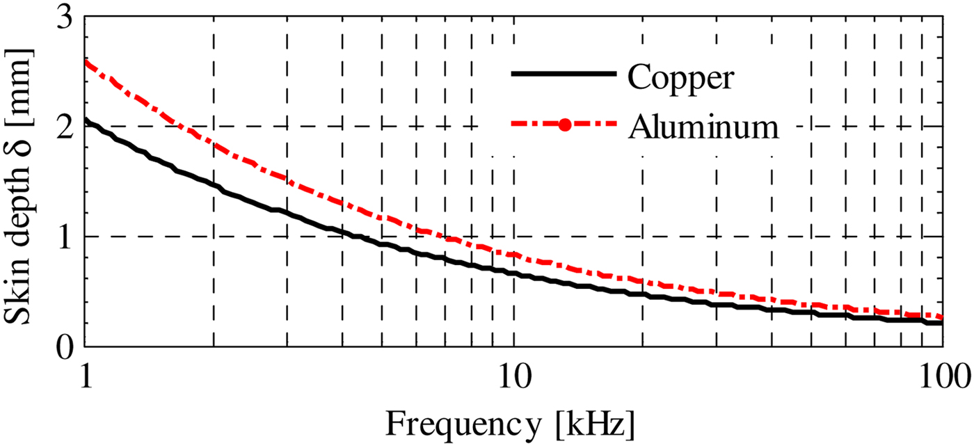
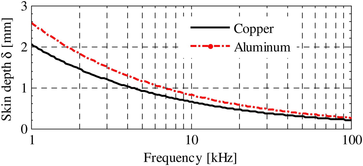
For magnetic near field sources, the most significant term in (2) is the absorption loss A dB = 20 log10(e t/δ ), t being the shield thickness and δ = (πfμσ) −1/2 the skin depth shown in Fig. 1 for copper and aluminum shields. The shielding performances of copper and aluminum are good enough (e.g., δ ≈ 0.25 mm at f = 85 kHz), but there is another relevant problem due to the eddy currents induced in the conductive shield producing a magnetic field opposite to the incident one. As a consequence, the inductive coupling between coils is reduced as well as the WPT performances. A further problem is given by the strong detuning of the WPT system due to the decrease of the inductances. Thus, the resonance condition can be obtained again at the nominal frequency only by varying the compensation capacitors [Reference Cruciani and Feliziani1, Reference Campi, Cruciani and Feliziani2].
Penetration depth in conductive materials (copper and aluminum).
B) Magnetic shielding
The magnetic shielding consists of using high magnetic permeability material panels that provide a preferential path for the magnetic flux lines. The incident magnetic field is not “blocked” as in conductive shields, but it is diverted into the magnetic material. The use of magnetic panels improves the quality of the WPT system for two separate reasons:
-
(1) the magnetic coupling between the primary and the secondary coil increases due to the presence of magnetic materials that can be assumed to be a portion of a magnetic core;
-
(2) the magnetic flux lines following the path of minimum reluctance are diverted from the region to be shielded into the magnetic materials producing a shielding effect.
The magnetic shielding effectiveness using magnetic shields is difficult to be evaluated by formulas since it mainly depends on the magnetic field configuration. However, at the frequency of interest, the use of low loss, high resistivity magnetic materials, such as ferrites, is highly recommended.
III. EQUIVALENT CIRCUIT
A) Equivalent circuit of a WPT system
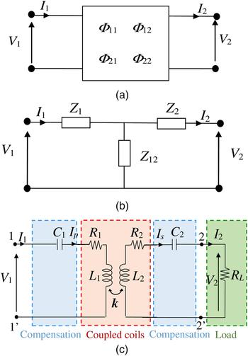
A WPT coil system without compensation can be modeled as a two-port network characterized by a 2 × 2 chain matrix Φ, as shown in Fig. 2(a). This network can be modeled by a T-type circuit (see Fig. 2(b)) with frequency-dependent impedances Z 1, Z 12, and Z 2 that depend on the WPT coil configuration. The relationships among Z 1, Z 12, Z 2 and the chain matrix coefficients Φ 11, Φ 12, Φ 21, and Φ 22 are given by
 $$Z_1 = ({\it \Phi} _{11} - 1)/{\it \Phi} _{21},$$
 $$Z_2 = ({\it \Phi} _{22} - 1)/ {\it \Phi} _{21},$$
 $$Z_{12} = 1/ {\it \Phi} _{21}.$$
The equivalent circuit of a WPT coil system modeled by a two-port network (a). T-type circuit with lumped impedances (b). SS configuration with load resistance R L (c).

To improve the WPT system performances, the primary and secondary coils are compensated introducing series or parallel capacitors to obtain the resonance condition [Reference Wang, Covic and Stielau9]. Considering series–series (SS) primary and secondary compensation blocks characterized by 2 × 2 chain matrices Φ c1 and Φ c2, respectively, the total chain matrix of the circuit in Fig. 2(c) is given by Φ t = Φ c1 Φ Φ c2.
The WPT efficiency is defined as
 $$\eta = {{P_2} / {P_1}},$$
where P 2 is the real power transferred to the load Z L and P 1 is the real power at the input port of the primary circuit, respectively. The efficiency can also be expressed as
 $$\eta = \displaystyle{{Re{\rm (}Z_L{\rm ) \vert} I_2{\rm \vert} ^2} \over {Re(Z_{in}) \vert I_1 \vert ^2}},$$
where Re is the real part operator, I 1 is the primary current at the port 1–1′, I 2 is the secondary current at the port 2–2′, and Z in is the input impedance at the port 1–1′ given by
 $$Z_{in} = \displaystyle{{{\it \Phi} _{t,11}Z_L + {\it \Phi} _{t,12}} \over {{\it \Phi} _{t,21}Z_L + {\it \Phi} _{t,22}}}.$$
In the equivalent circuit V 1 and V 2 are the port voltages, while I p and I s are the currents flowing into the coils. It should be noted that I 1 = I p and I 2 = I s for the SS compensation topology.
Applying (6) in (5), the WPT efficiency can be rewritten as:
 $$\eta = \displaystyle{{R_L} \over {Re{\rm (}({\it \Phi} _{t,11}R_L + {\it \Phi} _{t,12})conj({\it \Phi} _{t,21}R_L + {\it \Phi} _{t,22}){\rm )}}},$$
where conj represents the conjugate of a complex quantity and when the load impedance Z L = R L is purely resistive.
B) Coils in air
Two coils in the air can be modeled by the previously described equivalent circuits whose impedances are given by [Reference Campi, Cruciani and Feliziani2]
 $$Z_1 = R_1 + j\omega (L_1 - M),$$
 $$Z_2 = R_2 + j\omega (L_2 - M),$$
 $$Z_{12} = R_{12} + j\omega M,$$
where R 1 = R 1(ω) and R 2 = R 2(ω) are the coil resistances, L 1 = L 1(ω) and L 2 = L 2(ω) are the coil self-inductances, R 12 = R 12(ω) is the mutual resistance, if any, and M = k(L 1 L 2)1/2 is the mutual inductance, k being the coupling factor. The frequency dependence of the circuit parameters is due to the skin effect in the conductors. Compensation capacitors are added to the WPT system to obtain the resonance and improve the performances. For a SS configuration, the compensation capacitors at the resonant angular frequency ω 0 are given by [Reference Campi, Cruciani, De Santis, Palandrani, Hirata and Feliziani6]
 $$C_1 = 1/(\omega _0^2 L_1),$$
 $$C_1 = 1/(\omega _0^2 L_2),$$
and the efficiency η in the resonance condition and for a resistive load R L is given by
 $$\eta = \displaystyle{{R_L(R_{12}^2 + \omega _0^2 M^2)} \over {{(R_{12} + R_2 + R_L)}^2\left( {R_1 + \displaystyle{{(R_2 + R_L)R_{12} + \omega _0^2 M^2} \over {R_{12} + R_2 + R_L}}} \right)}}.$$
The efficiency η increases as ω 0 and k increase and as R 1, R 2, and R 12 decrease. Furthermore, the efficiency depends strongly on the load resistance R L [Reference Campi, Cruciani, De Santis and Feliziani5]. A similar behavior is observed for different capacitance compensation topologies, such as series-parallel (SP), parallel-series (PS), and parallel-parallel (PS) configurations [Reference Campi, Cruciani, De Santis, Palandrani, Hirata and Feliziani6].
C) Coils in the presence of lossy conductive materials
The equivalent circuit of a WPT system in the presence of lossy conductive materials in the surrounding has the same topology as described above, but with different values of lumped circuit parameters. Using the prime ′symbol for this new configuration, it yields that R′1 ≥ R 1, R′2 ≥ R 2, R′12 ≥ R 12, L′1 ≤ L 1, L′2 ≤ L 2, k′ ≤ k, M′ ≤ M. The coupling factor k is reduced because the time-varying magnetic field generated by the WPT system induces eddy currents on the conductive shield. Thus, these currents generate a magnetic field opposite to the incident one reducing the self-inductance of the coils and consequently the coupling factor.
D) Coils in the presence of magnetic lossless materials
Since the AC losses can be negligible in some magnetic materials with very low conductivity, i.e., ferrite, the equivalent circuit of a WPT in the presence of lossless magnetic materials in the surrounding is again the same. However, some circuit parameters are different from those with coils in the air due to the presence of the magnetic material that modifies the magnetic field behavior [Reference Cruciani and Feliziani1]. Using the asterisk * symbol for this configuration it yields: R 1* ≈ R 1; R 2* ≈ R 2; R 12* ≈ R 12; L 1* ≥ L 1; L 2* ≥ L 2; k* ≥ k; M* ≥ M. At the resonant frequency the efficiency increases, η* ≥ η, due to the increase of k*. This favorable behavior can be physically explained by the presence of the magnetic material that can be considered as a portion of a magnetic core improving the magnetic coupling (described by the increase of k*) and reducing the magnetic flux leakage. If the magnetic shield is lossy, the behavior can be described by a combination of the previous equations for conductive and lossless magnetic materials. In this case, it is quite impossible to know a priori if the efficiency increases or decreases
IV. METHOD VALIDATION
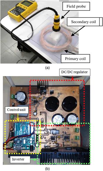
In order to validate the numerical results and experimentally evaluate the shielding performances of simple shielding panels, a WPT demonstrator has been realized, as shown in Fig. 3(a). The primary coil is fed by an inverter that generates a square wave voltage source V s at the nominal frequency f 0 = 85 kHz. The value of versus is regulated using a DC/DC converter before the inverter (see the picture in Fig. 3(b)) in order to transfer a fixed power P 2 = 100 W to a resistive load R L = 5 Ω.
WPT demonstrator. (a) Measurement setup. (b) Realized inverter with DC/DC regulator.

Three test cases are examined:
-
• coils in the air without a shield;
-
• coils in the presence of an aluminum conductive shield placed near the secondary coil;
-
• coils in the presence of a ferrite magnetic shield placed near the secondary coil.
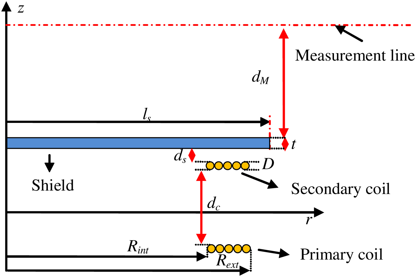
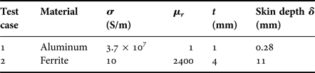
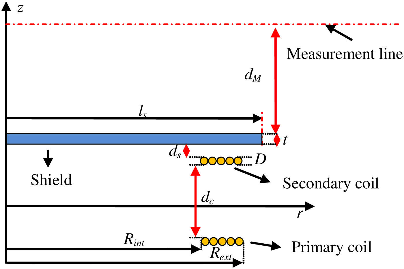
As shown in Fig. 4, the shielding panels of conductive or magnetic material have side length l s = 15 cm and different thickness t. The WPT demonstrator has two identical coaxial planar coils with N 1 = N 2 = 5 turns, internal coil radius R int = 70 mm, external coil radius R ext = 83.5 mm, enameled copper wire with diameter D = 2.5 mm, and the distance between the stacked coils d c = 40 mm. The panels under test are placed parallel to the secondary coil at a distance d s = 3 mm, and their characteristics are reported in Table 1.
2D axially-symmetric configuration of a two-coil system in presence of a shielding panel used for the method validation.
Shield configurations at 85 kHz.

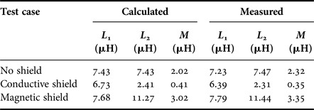
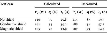
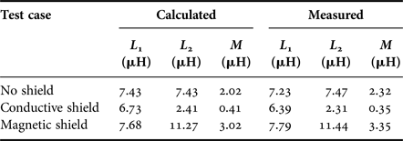
First, the equivalent circuit parameters of the WPT coil system are extracted by a numerical software tool based on the finite element method (FEM) [Reference Campi, Cruciani, De Santis, Palandrani, Hirata and Feliziani6], as reported in Table 2. The equivalent circuit analysis is then used to evaluate the efficiency η, the real power P 1 and the primary coil currents I p , when the load power P 2 = 100 W and I 2 = I s = 4.4 A are fixed. The measured values are compared with those obtained by the circuit analysis as reported in Table 3. The output power P 2 in both calculations and measurements is kept fixed by adjusting the input voltage V 1 of the source block.
Measured and calculated inductances at 85 kHz.
Measured and calculated electrical quantities.
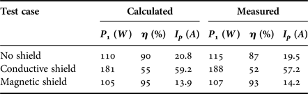
It should be noted that the presence of a conductive shield leads to a reduction of k and therefore of the WPT performance, while the presence of a low loss magnetic shield leads to an increase of k and therefore of the WPT performance.
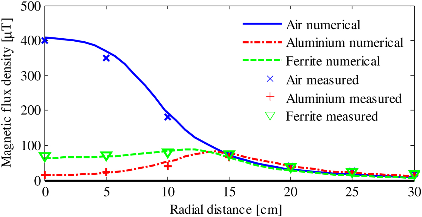
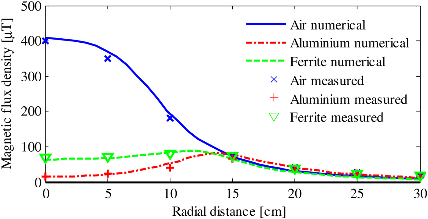
Finally, the magnetic flux density vector B is evaluated by a FEM electromagnetic field solver assuming as magnetic field sources the coil currents I p and I s derived from the circuit analysis [Reference Campi, Cruciani, Maradei and Feliziani12]. The rms magnitude | B| of the magnetic flux density is calculated and measured at a distance d M = 8 cm above the secondary coil for the three test cases, as shown in Fig. 5, where a good agreement is observed. From the obtained results we draw the following conclusions: the presence of a conductive panel provides excellent shielding performance but the WPT efficiency is drastically reduced, while a magnetic shield could lead to both a good shielding and high efficiency of the WPT system when it is adequately designed.
Magnetic flux density | B | along the r-axis at z = d M + t + d s + D + d c /2.
V. AUTOMOTIVE APPLICATIONS
A realistic automotive WPT application is also examined. The considered WPT system is designed and optimized to efficiently transfer a power of 7.7 kW to the load which models the battery charger of a mid-size car. The WPT system operates at 85 kHz and has two identical circular planar coils, with external diameter R out = 250 mm and number of turns N 1 = N 2 = 10. The distance between the stacked coils is d c = 200 mm. The coils are made of Litz wire to reduce the AC losses at the considered frequency [Reference Campi, Cruciani, Maradei and Feliziani21]. The Litz wire is composed of 1050 strands of AWG 38 copper wire with a geometrical diameter of about D = 6 mm. The load is modeled as a simple power resistor R L = 10 Ω. The SS compensation topology is adopted and the WPT system is fed by a time-harmonic voltage generator source V s [Reference Campi, Cruciani, Maradei and Feliziani21, Reference Feliziani22]. Due to the geometrical complexity, the AC resistance of the Litz wire coils is not calculated but obtained from datasheets. Their values are R 1 = R 2 = 94 mΩ at the frequency of 85 kHz.
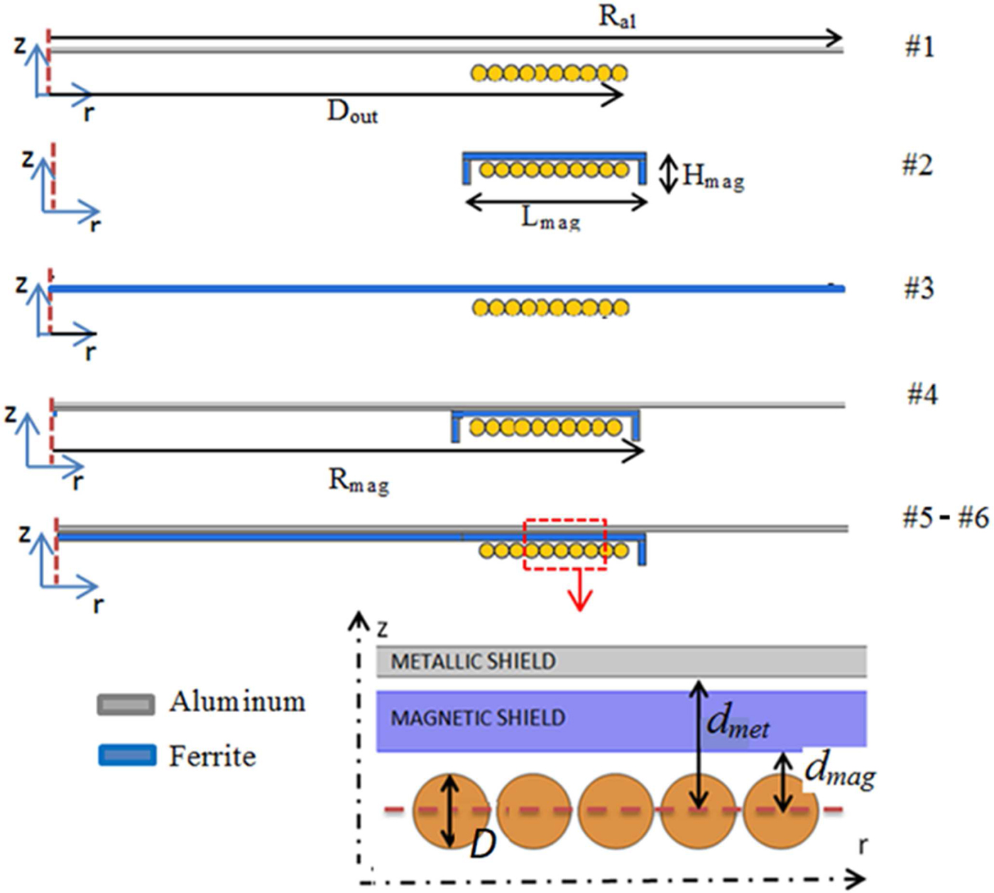
Several shielding configurations assuming conductive shields, magnetic shields, or a combination of conductive and magnetic shields are considered, as shown in Fig. 6. The shield configurations of the primary and secondary coils are identical. The examined new test case configurations are:
-
#0: no shield (i.e., coils in the air);
-
#1: conductive shield;
-
#2–3: magnetic shields;
-
#4–5–6: combinations of magnetic and conductive shields.
2D axially-symmetric shield configuration for test cases #1–6 (only the secondary coil is depicted since the primary coil is specular).
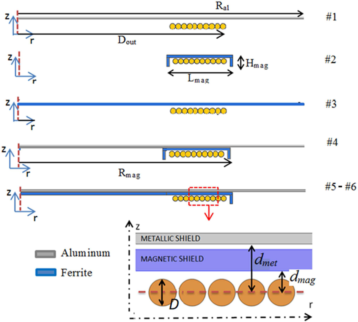
In the test cases, #1, #4, #5, and #6 the conductive shield is made by an aluminum disk with radius R al = 500 mm, thickness t = 2 mm, μ r = 1, and σ = 37 MS/m. The material used for all magnetic shields is a ferrite of different shape and dimension but always characterized by a relative permeability μ r = 2400 and conductivity σ = 10 S/m.
The ferrite shield thickness is t = 4 mm for all test cases except for case #3, where a thicker shield of t = 6 mm is considered. In the test cases, #2 and #4 the magnetic shields are shaped as a circular corona with a C-shaped cross-section having dimensions L mag = 100 mm and H mag = 30 mm. In the test cases, #5 and #6 the magnetic shield is a disk with the L-shaped section, while in test case #3 the magnetic shield is a simple disk with radius R mag = 500 mm. The distance between the magnetic shields and the coil is d mag = 5 mm. The distance from the conductive shield to the coil is d met = 11 mm for all cases, except for test case #6 where the distance is set to d met = 22 mm. Cases #5 and #6 are presented to verify the influence of the parameter d met on the efficiency and on the magnetic field.
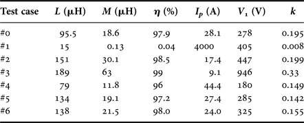
The lumped circuit parameters and the WPT performance quantities (i.e., self-inductance L 1=L 2 = L, mutual inductance M, efficiency η, input voltage V 1, and current I 1) are calculated following the method described in the previous section. Table 4 summarizes the obtained results of all the considered test cases. It should be noted that for each test case the values of the compensation capacitor has been updated to reach the resonant condition at 85 kHz by (9).
Circuit lumped parameters and electrical performances.

The SE H in WPT systems is not clearly defined since the introduction of a conductive shield affects the inductive coupling modifying the incident field Hi [Reference Cruciani and Feliziani1, Reference Campi, Cruciani and Feliziani2]. In this work, the calculation of SE H is performed keeping constant the output quantities P 2, V 2, and I 2. The primary voltage V 1 is adjusted for each test case in order to keep fixed the power level delivered to the load at P 2 = 7.7 kW. The output voltage is V 2 = 277 V, while the output current is I 2= 28 A.
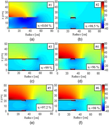
The magnetic shielding effectiveness SE H is then calculated at any point by (1) using an eddy current solver. The maps of the shielding effectiveness for all test cases are shown in Fig. 7, when considering Hi the field produced by the WPT coil currents in absence of shielding (i.e., in air) when P 2 = 7.7 kW and I 2 = 28 A. In the test case #1 (only large conductive shield simulating the vehicle chassis) the SE H is significant but, as described above, the WPT efficiency is very low and makes the system useless. In the test case #2 and #3 (only magnetic material), the shielding effect is poor in the case #2 while in the test case #3 where the larger dimension and thickness of the shield leads to good SE H performances. Furthermore, the use of only magnetic shield permits to optimize the WPT performances with a maximum efficiency of 99% obtained for test case #3. In the other test cases (#4–6), the magnetic and conductive shields are combined placing the magnetic field between the coil and the conductive shield. These configurations produce similar results in terms of shielding effectiveness and WPT efficiency. The small differences between them are mostly due to the different geometrical configuration of the magnetic shield that diverts the magnetic flux lines in a different way. The best compromise in terms of SE H and η is obtained for the electro-geometrical configurations of test cases #5 and #6. However, the increment of the distance between the metallic shield and the coils (d met ) leads to a very small increase in the efficiency, while the SE H maps are almost identical. Since the increase of d met could lead to mechanical problems, together with space and weight, there is no point to suggest test case #6.
Maps of shielding effectiveness SE H for test cases #1 (a), #2 (b), #3 (c), #4 (d), #5 (e), and #6 (f).

Finally, the magnetic field distribution inside a realistic EV chassis made of aluminum has been calculated considering a shielding configuration similar to the test case #5. In this case, the metallic shield is replaced by the presence of the EV bodyshell [Reference Campi, Cruciani, De Santis, Maradei and Feliziani4]. This last is assumed to be of aluminum alloy with conductivity σ = 30 MS/m and thickness t = 2 mm. The car outer dimensions are length l = 4.3 m, width w = 1.7 m, and height h = 1.2 m.
To reproduce the real environment in the simulations and to accurately calculate the currents on the coils, the simplified equivalent circuits of the source and load blocks (see again Fig. 2) are replaced with more realistic electronic blocks, as schematically reported in Fig. 8. On the transmitting side, the AC voltage is converted in DC by a rectifier and then a DC/DC converter permits to regulate the feeding voltage of the inverter. This block is used to adjust the output power using an output power feedback given from the battery through a dedicated wireless transmission [Reference Campi, Cruciani, Maradei and Feliziani23].
Block diagram of WPT charger.
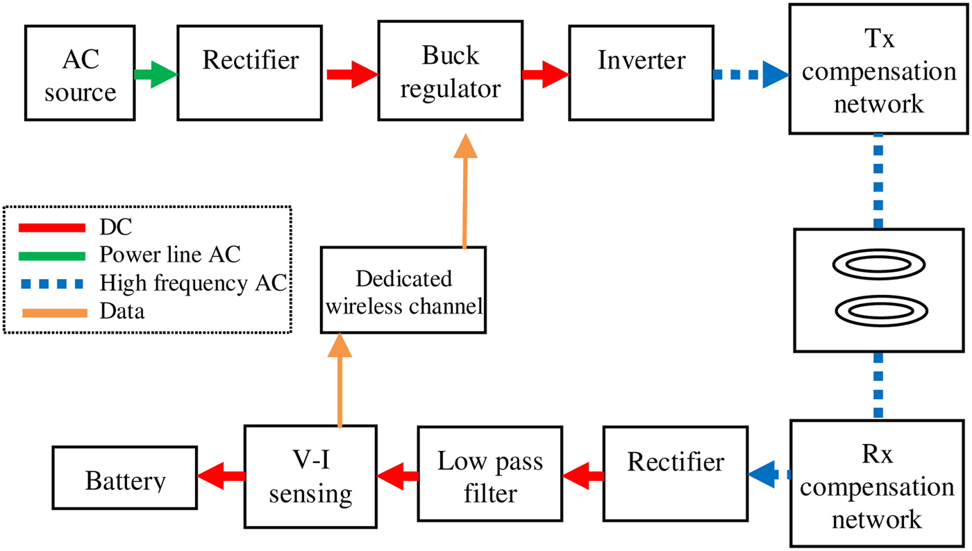
The inverter converts the DC voltage into an AC voltage at the resonant frequency f 0. On the receiving side, the high-frequency AC voltage is firstly rectified and then filtered and connected to the battery. In the SPICE simulations, a full bridge inverter with IPW60R045CPA MOSFETs is considered at the transmitting side, while a bridge rectifier (composed of DDB6U145N16L diodes) and a simple LC filter with L = 0.1 µH and C = 100 µF is applied to the receiving side.
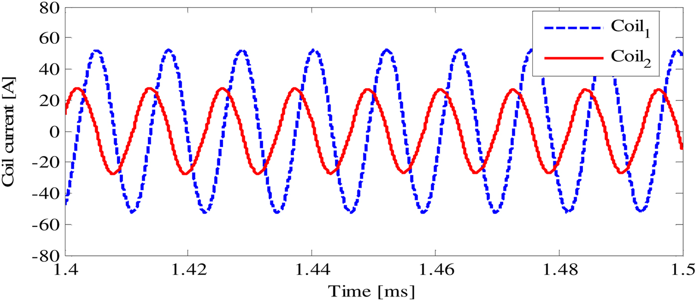
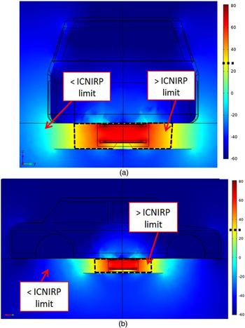
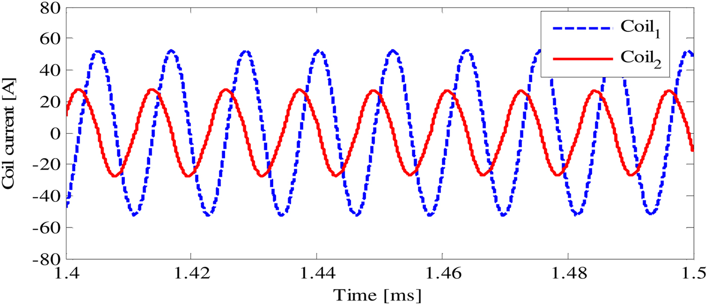
The calculated RMS currents in the primary and secondary coils using SPICE are I 1 = 22.2 A and I 2 = 37.2 A, and their waveforms are reported in Fig. 9. The magnetic field is then calculated imposing I p = I 1 and I s = I 2 as magnetic field sources in the eddy current solver. The calculated maps of | B| are shown in Fig. 10, where the ICNIRP 2010 reference level (B RL = 27 µT (= 28.63 dBµT) @ f = 85 kHz) are also reported highlighting the zones where the limits are exceeded.
Waveforms of the currents on the primary and secondary coils.
Magnetic field distribution inside and outside the EV in dBµT. Front view (a). Lateral view (b).

VI. CONCLUSIONS AND DISCUSSIONS
A numerical and experimental analysis has been carried out to evaluate the shielding performances of conductive and magnetic shields excited by two planar coils of a WPT system. Particular attention has been focused on the influence of the shield types and configurations on the electrical performances of the system. The presence of conductive shields generates relevant eddy currents and good shielding performance, but it reduces dramatically the efficiency of the WPT system. On the contrary, the use of a high permeability and low loss material, such as the ferrite, improves the electrical performances of a WPT system. However, to obtain good shielding results, a relevant amount of ferrite could be necessary making the WPT system expensive and cumbersome. The use of a combination of both magnetic and conductive shields permits to maintain high electrical efficiency and excellent shielding performances.
The aforementioned considerations must be kept in mind when considering also the material composition and thickness of the car chassis. For instance, in current EVs made mainly by aluminum alloys, a single magnetic (e.g., ferrite) shield placed under the car platform could be enough to reach reasonable performances. Instead, in future EVs, where the chassis will be made of poor conductive materials, such as carbon fibers composite, the use of only magnetic shields could be impracticable due to the excessive thickness and thus the weight of the same. In this case, a combination of adequate magnetic and conductive shields could be the most affordable solution. Indeed, a very thin (i.e., around 0.3 mm thick equal to the skin depth at these frequencies) aluminum foil would be light but good enough to shield the magnetic field while the ferrite permits to maintain the electrical performances at an acceptable level.