1 Introduction
The performance of high-powered cutting-edge miniature electronic devices depends on the heat dissipation efficiency, and ineffective heat removal can lead to undesired results (Bodla, Weibel & Garimella Reference Bodla, Weibel and Garimella2013). The heat generation in such small devices is the most problematic issue, and failing to control it renders the application of such devices economically untenable (Schelling, Shi & Goodson Reference Schelling, Shi and Goodson2005). The source of the heat can be electromagnetic (Klinbun, Vafai & Rattanadecho Reference Klinbun, Vafai and Rattanadecho2012), radiation (Mahmoudi Reference Mahmoudi2014), electrochemical (Benger et al. Reference Benger, Wenzl, Beck, Jiang, Ohms and Schaedlich2009; Jeon & Baek Reference Jeon and Baek2011) and/or related to resistivity (Barletta et al. Reference Barletta, Lazzari, Magyari and Pop2008). A promising method to mitigate the overheating problem is the use of microchannel heat sinks (MCHS) (Lu & Vafai Reference Lu and Vafai2016). The advantages of such devices include high surface-to-volume ratio, portability and low coolant requirements (Kandlikar & Grande Reference Kandlikar and Grande2002; Pourmehran et al. Reference Pourmehran, Rahimi-Gorji, Hatami, Sahebi and Domairry2015). To further increase the available surface for heat transfer, MCHS with built-in porous media have been used (Jiang et al. Reference Jiang, Fan, Si and Ren2001; Chen & Huang Reference Chen and Huang2012; Huang, Chen & Hwang Reference Huang, Chen and Hwang2013; Ghahremannezhad & Vafai Reference Ghahremannezhad and Vafai2018; Ghahremannezhad et al. Reference Ghahremannezhad, Xu, Nazari, Ahmadi and Vafai2019). In addition to larger surface-to-volume ratio, such porous media also improve mixing which leads to higher heat transfer in MCHS (Hung, Huang & Yan Reference Hung, Huang and Yan2013; Hidalgo & Dentz Reference Hidalgo and Dentz2018). Using a similar concept, pin-based MCHS have been shown to successfully dissipate heat by increasing available surface area for heat transfer (Ahmed et al. Reference Ahmed, Salman, Kherbeet and Ahmed2018). The pin-based MCHS are not only easy to manufacture but also easy to optimize for a specific system (Rubio-Jimenez, Kandlikar & Hernandez-Guerrero Reference Rubio-Jimenez, Kandlikar and Hernandez-Guerrero2012; Ndao, Peles & Jensen Reference Ndao, Peles and Jensen2014; Zhao et al. Reference Zhao, Huang, Gong and Huang2016). There have been several studies of the performance of microchannels fully filled with porous media (Hasan Reference Hasan2014; Ahmed et al. Reference Ahmed, Salman, Kherbeet and Ahmed2018). Despite the heat transfer enhancement, such systems have high pressure drop which may result in some performance inefficiency (Sung, Kim & Hyun Reference Sung, Kim and Hyun1995; Gallego & Klett Reference Gallego and Klett2003; Hung et al. Reference Hung, Huang and Yan2013). Partially filled porous channels, however, have less pressure drop as the coolant can flow through the porous medium as well as around it (Leong et al. Reference Leong, Li, Jin and Chai2010). It has also been shown that there is no need to fill the whole system with porous medium to reach the maximum possible heat transfer, and partially filled microchannels can perform as efficiently as fully filled ones (Poulikakos & Kazmierczak Reference Poulikakos and Kazmierczak1987; Chikh et al. Reference Chikh, Boumedien, Bouhadef and Lauriat1995a ,Reference Chikh, Boumedien, Bouhadef and Lauriat b ). The hydrodynamic behaviour of partially filled pin-based MCHS is very complex as there are various flow regimes in the system (Griffith et al. Reference Griffith, Thompson, Leweke, Hourigan and Anderson2007; Nazari, Mohebbi & Kayhani Reference Nazari, Mohebbi and Kayhani2014; Zargartalebi & Azaiez Reference Zargartalebi and Azaiez2018b ). This complexity may lead to unpredictable behaviour in terms of heat removal performance.
This study is, therefore, aimed at analysing the effects of porous medium size on both heat transfer and flow patterns in a partially filled MCHS. The effects of the structure of pin distribution, which is representative of the porous medium, are also taken into consideration. The study also examines if previous results regarding the pin configuration for fully filled microchannels can be extended to partially filled ones. A particle tracing technique is used to further analyse the flow dynamics in the system. An analytical approach is finally adopted to analyse the parameters affecting the behaviour of the MCHS.
2 Model description
In this section, first, the geometry of the model along with the boundary conditions and assumptions will be discussed. Then, the governing equations with the numerical method adopted to solve them will be presented.
2.1 Geometry of the model
The built-in porous MCHS of length
 $L$
in the horizontal (
 $x$
-)direction and height
 $H$
in the transverse (
 $y$
-)direction is partially filled with pins as shown in figure 1. The height of the porous part
 $(H_{p})$
which is filled with pins can change, while its length
 $(L_{p})$
is constant. This is to be contrasted with a fully filled MCHS where the porous medium occupies the whole domain, i.e.
 $H_{p}=H,L_{p}=L$
(see figure 1). The depth of the pins is assumed to be large such that a two-dimensional model can capture the system dynamics and their distribution can be either inline or staggered. It is worth mentioning that porous medium refers here to the area that is filled with pins and these expressions will be used interchangeably. The numbers of pins in the longitudinal and transverse directions are determined as
 $(L_{p}/2D_{pin})$
and
 $(H_{p}/2D_{pin})$
, leading to a porosity
 $\unicode[STIX]{x1D719}=1-\unicode[STIX]{x03C0}/6\approx 0.8$
. The pins are assumed to be connected to a hot surface and therefore their surface is maintained at a hot temperature
 $T_{h}$
. No-slip, no-flow boundary conditions are assumed for the pin surface as well as the horizontal boundaries. The coolant which is a Newtonian fluid at temperature
 $T_{c}<T_{h}$
is injected from the left-hand boundary of the MCHS at a constant velocity
 $U$
. All the properties of the coolant are considered to be constant and the coolant and the resident fluid in the MCHS are assumed to be fully miscible and have the same physical properties. The right-hand boundary of the MCHS is assumed to be an open boundary while the horizontal ones are assumed to be adiabatic.
Schematic of the system.

2.2 Governing equations
The governing equations for this system are the conservation of mass, momentum and energy:
 $$\begin{eqnarray}\displaystyle & \displaystyle \unicode[STIX]{x1D735}\boldsymbol{\cdot }(u)=0, & \displaystyle\end{eqnarray}$$
 $$\begin{eqnarray}\displaystyle & \displaystyle \unicode[STIX]{x1D70C}{\displaystyle \frac{Du}{Dt}}=-\unicode[STIX]{x1D735}P+\unicode[STIX]{x1D735}\boldsymbol{\cdot }(\unicode[STIX]{x1D707}[\unicode[STIX]{x1D735}u+(\unicode[STIX]{x1D735}u)^{t}]), & \displaystyle\end{eqnarray}$$
 $$\begin{eqnarray}\displaystyle & \displaystyle \unicode[STIX]{x1D70C}c{\displaystyle \frac{DT}{Dt}}=\unicode[STIX]{x1D735}\boldsymbol{\cdot }k\unicode[STIX]{x1D735}T, & \displaystyle\end{eqnarray}$$
where
 $P$
and
 $u=(u_{x},u_{y})$
stand for the isotropic pressure and velocity vector, respectively,
 $\unicode[STIX]{x1D707}$
denotes the dynamic viscosity, while
 $\unicode[STIX]{x1D70C}$
and
 $c$
are the density and specific heat capacity of the coolant, respectively. The temperature of the system is denoted by
 $T$
and the heat conductivity is shown by
 $k$
, while
 $D/Dt$
represents the total/material derivative. Using the following variables, the equations can be formulated in dimensionless form:
 $$\begin{eqnarray}x^{\ast }={\displaystyle \frac{x}{D_{pin}}},\quad y^{\ast }={\displaystyle \frac{y}{D_{pin}}},\quad u^{\ast }={\displaystyle \frac{u}{U}},\quad t^{\ast }={\displaystyle \frac{tU}{D_{pin}}},\quad P^{\ast }={\displaystyle \frac{P}{\unicode[STIX]{x1D70C}U^{2}}},\quad \unicode[STIX]{x1D703}={\displaystyle \frac{T-T_{c}}{T_{h}-T_{c}}}.\qquad\end{eqnarray}$$
To characterize the geometry of the system, the following dimensionless parameters are used:
 $$\begin{eqnarray}\displaystyle i^{\ast }={\displaystyle \frac{i}{D_{pin}}}, & & \displaystyle\end{eqnarray}$$
where
 $i=L,H,l,h,L_{p},H_{p},L_{1},H_{1}$
. The parameters
 $L^{\ast },H^{\ast },L_{p}^{\ast }$
and
 $H_{p}^{\ast }$
are longitudinal and transversal dimensionless length of the MCHS and porous medium, respectively. The longitudinal and transversal dimensionless distances between the pins are denoted by
 $l^{\ast }$
and
 $h^{\ast }$
, respectively. Parameters
 $H_{1}^{\ast }$
and
 $L_{1}^{\ast }$
are the transversal and longitudinal dimensionless position of the left-bottom tip of the porous medium. The governing equations in dimensionless form are
 $$\begin{eqnarray}\displaystyle & \displaystyle \unicode[STIX]{x1D6FB}^{\ast }\cdot (u^{\ast })=0, & \displaystyle\end{eqnarray}$$
 $$\begin{eqnarray}\displaystyle & \displaystyle {\displaystyle \frac{D^{\ast }u^{\ast }}{D^{\ast }t^{\ast }}}=-\unicode[STIX]{x1D6FB}^{\ast }P^{\ast }+{\displaystyle \frac{1}{Re}}\unicode[STIX]{x1D6FB}^{\ast }\cdot (\unicode[STIX]{x1D6FB}^{\ast }u^{\ast }+(\unicode[STIX]{x1D6FB}^{\ast }u^{\ast })^{t}), & \displaystyle\end{eqnarray}$$
 $$\begin{eqnarray}\displaystyle & \displaystyle {\displaystyle \frac{D^{\ast }\unicode[STIX]{x1D703}}{D^{\ast }t^{\ast }}}={\displaystyle \frac{1}{Re\cdot Pr}}\unicode[STIX]{x1D6FB}^{\ast 2}\unicode[STIX]{x1D703}, & \displaystyle\end{eqnarray}$$
where the dimensionless parameters representing the Reynolds number,
 $Re$
, and Prandtl number,
 $Pr$
, are
 $$\begin{eqnarray}\displaystyle Re={\displaystyle \frac{\unicode[STIX]{x1D70C}UD_{pin}}{\unicode[STIX]{x1D707}}},\quad Pr={\displaystyle \frac{\unicode[STIX]{x1D707}c}{k}}. & & \displaystyle\end{eqnarray}$$
The performance of the MCHS is determined using the Nusselt number
 $$\begin{eqnarray}\displaystyle Nu={\displaystyle \frac{h_{conv}D_{pin}}{k}}. & & \displaystyle\end{eqnarray}$$
Here
 $h_{conv}$
is the convective heat transfer coefficient which can be determined as follows (Lavasani & Bayat Reference Lavasani and Bayat2016; Halkarni, Sridharan & Prabhu Reference Halkarni, Sridharan and Prabhu2017):
 $$\begin{eqnarray}\displaystyle h_{conv}={\displaystyle \frac{\dot{Q}}{s\unicode[STIX]{x0394}T_{n}}}, & & \displaystyle\end{eqnarray}$$
where the total surface area of the pins, considering unit value for the third dimension, is denoted by
 $s$
. The heat carriage by the fluid can be determined using the following equation (Lavasani & Bayat Reference Lavasani and Bayat2016; Halkarni et al.
Reference Halkarni, Sridharan and Prabhu2017):
 $$\begin{eqnarray}\displaystyle \dot{Q}={\dot{m}}c(T_{out}-T_{in}). & & \displaystyle\end{eqnarray}$$
In the above equation
 ${\dot{m}}$
and
 $c$
represent the total mass flow rate and specific heat capacity of the coolant, respectively, while
 $T_{out}$
and
 $T_{in}$
are the average outlet and inlet temperature of the MCHS, respectively. The normalized temperature difference across the MCHS,
 $\unicode[STIX]{x0394}T_{n}$
, is determined as follows (Lavasani & Bayat Reference Lavasani and Bayat2016):
 $$\begin{eqnarray}\displaystyle \unicode[STIX]{x0394}T_{n}={\displaystyle \frac{(T_{pin}-T_{out})-(T_{pin}-T_{in})}{\ln \left({\displaystyle \frac{T_{pin}-T_{out}}{T_{pin}-T_{in}}}\right)}}, & & \displaystyle\end{eqnarray}$$
where
 $T_{pin}$
is the temperature of the pin surface, which in this study is equal to
 $T_{h}$
. Using the dimensionless parameters, the Nusselt number can be expressed in terms of other dimensionless variables as follows:
 $$\begin{eqnarray}\displaystyle Nu=RePr{\displaystyle \frac{H^{\ast }\unicode[STIX]{x0394}\unicode[STIX]{x1D703}}{N\unicode[STIX]{x03C0}\unicode[STIX]{x0394}\unicode[STIX]{x1D703}_{n}}}, & & \displaystyle\end{eqnarray}$$
in which
 $N$
is the number of pins in the MCHS.
The governing equations were solved using the lattice Boltzmann method in a
 $D_{2}Q_{9}$
space for both momentum and energy evolutions (SukopMC Reference Sukop and Thorne2005; Mohamad Reference Mohamad2011). The lattice Boltzmann method space is related to real space, using the dimensionless numbers. The evolution of the momentum has been solved using the multi-relaxation time approach, while the single relaxation time approach has been adopted to solve for the energy in the system (Bhatnagar, Gross & Krook Reference Bhatnagar, Gross and Krook1954; Higuera & Jiménez Reference Higuera and Jiménez1989). The momentum and energy relaxation times were related to the kinematic viscosity and thermal diffusivity, respectively, using Chapman–Enskog expansion (Mohamad Reference Mohamad2011). The inlet boundary condition is defined using the Zho–He boundary condition (Zou & He Reference Zou and He1997), while the outlet boundary condition is considered to be an open boundary (Mohamad Reference Mohamad2011). The second-order bounce-back boundary condition is adopted for the no-slip boundaries (SukopMC Reference Sukop and Thorne2005; Mohamad Reference Mohamad2011). The parameters have been chosen such that the Mach number is in the range of the lattice Boltzmann method incompressibility limit and to ensure that the stability limits are met (Mohamad Reference Mohamad2011). The developed code has been validated using various experimental and numerical techniques. For the sake of brevity, however, the validation and the grid dependency analyses are not included here.
3 Results and discussion
This section is divided into three sub-sections. The first one focuses on the qualitative differences of the flow geometry and temperature distribution of the inline and staggered configurations and analyses the effects of the height of the porous medium on the MCHS performance. The second sub-section presents a quantitative analysis of the aforementioned differences and examines general patterns based on governing dimensionless numbers. Using a simple flow model, the last sub-section focuses on analysing the flow dynamics and the parameters affecting the performance of the MCHS.
For generality and wide applicability of the conclusions, the results and analysis are based on dimensionless numbers. Given the large number of dimensionless numbers in the system, the study will focus on those believed to play important roles in MCHS performance. Therefore, unless mentioned otherwise, the parameters
 $Pr$
,
 $L^{\ast }$
,
 $H^{\ast }$
,
 $D_{pin}^{\ast }$
,
 $l^{\ast }$
,
 $h^{\ast }$
,
 $L_{p}^{\ast }$
and
 $L_{1}^{\ast }$
are fixed as
 $Pr=1$
,
 $L^{\ast }=32$
,
 $H^{\ast }=16$
,
 $D_{pin}^{\ast }=1$
,
 $l^{\ast }=1$
,
 $h^{\ast }=1$
,
 $L_{p}^{\ast }=8$
and
 $L_{1}^{\ast }=4$
. The analysis has been conducted in transient condition at
 $t^{\ast }=40$
which ensures that the temperature front reaches the outlet boundary.
3.1 Qualitative analysis of the pin configuration
As already mentioned in the literature, the pin configuration has an important effect on the MCHS performance (Ahmed et al. Reference Ahmed, Salman, Kherbeet and Ahmed2018; Zargartalebi & Azaiez Reference Zargartalebi and Azaiez2018a , Reference Zargartalebi and Azaiez2019). Most previous MCHS studies have, however, focused almost exclusively on configurations were the whole domain is filled with pins and the only available area for the coolant to flow is limited to the porous medium (Ahmed et al. Reference Ahmed, Salman, Kherbeet and Ahmed2018). Accordingly, there is a dearth of studies of systems where the domain is only partially occupied by the porous medium (Nazari et al. Reference Nazari, Mohebbi and Kayhani2014). When the pins are partially embedded within the medium, the hydrodynamics of the flow is quite different from that of the fully filled porous MCHS, and conclusions drawn for fully filled pin-based MCHS may not be actually valid. In particular, in the case of partially porous embedded MCHS, the size of the porous medium as well as the pin configuration are expected to play important roles in the flow geometry as well as in the system performance.
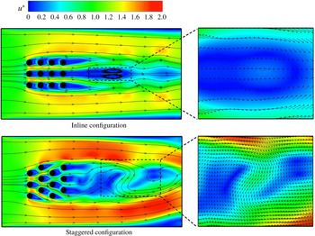
Figure 2 illustrates the dimensionless velocity profiles of two MCHS with two pin configurations, staggered and inline, for
 $H_{p}^{\ast }=6$
. As can be seen, in a partially filled porous MCHS, regardless of the pin configuration, the coolant tends to select the path of least resistance, flowing mainly through regions where there are no pins. The flow structures are, however, dependent on the pin configuration with clearly different streamlines and velocity profiles in the inline and staggered configurations.
Comparison of velocity profiles of inline and staggered configurations;
 $Re=100,H_{p}^{\ast }=6$
.

In the staggered configuration, unlike the inline one, not only are the streamlines asymmetric but also the flow is more prone to go through the least-resistance areas. This can be attributed to the fact that the resistivity in the staggered configuration is stronger than in the inline one, and therefore the coolant tends to bypass the porous medium. The flow structure downstream of the porous medium is also different as shown in the zoomed-in panels. The velocity vectors in the staggered configuration reveal that there is a flow from the low-resistance area to the downstream region while the flow structures of the inline configuration show some vortexes with no inward flow from the low-resistance area. Figure 3 compares the dimensionless pressures for the inline and staggered configurations for
 $H_{p}^{\ast }=6,12$
. As can be seen in figure 3(a,b), the pressure build-up upstream of the staggered configuration is larger than in the inline one. This larger resistance in the staggered configuration hinders the coolant from entering the porous medium. Moreover, as the staggered configuration offers lower permeability than the inline one, the coolant can hardly travel through this porous structure, and therefore the pressure build-up inside the staggered configuration is higher than in the inline one.
Comparison of pressure profiles of inline and staggered configurations for (a,b)
 $H_{p}^{\ast }=6$
and (c,d)
 $H_{P}^{\ast }=12$
;
 $Re=100$
.

Comparison of temperature profiles of inline and staggered configurations for (a,b)
 $H_{p}^{\ast }=6$
and (c,d)
 $H_{P}^{\ast }=12$
;
 $Re=100$
.

Figure 4 depicts the temperature profile for both inline and staggered configurations for
 $H_{p}^{\ast }=6,12$
. It can be observed in figure 4(a,b) that the energy release in the inline configuration is symmetric reflecting limited to no intermixing between the high-temperature mixed coolant leaving the porous medium and the low-temperature unmixed one flowing in the low-resistance areas. This non-intermixing can be attributed to the particular flow development seen in figure 2. In the staggered configuration, however, because of the particular flow dynamics (see figure 2), there is a strong intermixture between the heated coolant and the cold coolant flowing in the low-resistance area where there are no pins to increase the temperature. This strong intermixing leads to an overall low efficiency of the MCHS meaning that less heat is removed from the pin surface.
This unexpected result is opposite to what has been reported in fully filled pin-based MCHS, where it has been shown that staggered configurations result in higher efficiency than inline ones. This difference is probably a result of the fact that the porous medium here does not occupy the whole domain. It is suspected that the size of the porous medium can affect the results as both the inner porous medium flow rate and the outer flow rate play a crucial role in the heat transfer process. As such, the same system but with larger porous medium height is now analysed to determine how this may affect the MCHS efficiency. Figure 4(c,d) illustrates the temperature profile for both inline and staggered systems with larger porous medium height
 $(H_{p}^{\ast }=12)$
. The effluent temperature in the staggered configuration is clearly higher than in the inline one, implying that the staggered configuration has now become more efficient than the inline one.
The better performance of the staggered configuration can be attributed to the fact that unlike the previous system, the height of the porous medium is larger and, as such, the low-resistance regions, above and below the porous medium, have become narrower. Therefore, the contribution of the porous medium to the flow increases resulting in the better performance of the staggered configuration. As one can see, there is less intermixing for this staggered configuration compared to the configuration with smaller height. This smaller intermixture enhances the performance of the partially filled pin-based MCHS as discussed before.
Figure 3(c,d) shows the dimensionless pressure of the inline and staggered configurations with large porous medium height. It can be seen that compared to the case of small porous medium height (figure 3 a,b), for both configurations the pressure build-up is higher in the upstream region of the porous medium which indicates that the porous medium is playing a more important role and the coolant is forced to flow through the porous medium rather than the low-resistance regions.
All of the above-mentioned analyses are based on qualitative results. The next section is devoted to a quantitative analysis, considering the effects of different hydrodynamic and geometric parameters.
3.2 Quantitative analysis of the pin configuration
A quantitative analysis helps in studying the effects of multifarious parameters at the same time and determining if there are any general trends regarding the behaviour of the MCHS. In this section, the performance of MCHS at different porous medium heights and Reynolds numbers is examined. The performance of MCHS will be evaluated using both the Nusselt number and the friction factor. The friction factor is defined as the difference between the inlet and outlet dimensionless pressures (Lavasani & Bayat Reference Lavasani and Bayat2016).
Figure 5 depicts the variation of the Nusselt number with the Reynolds number for four different porous medium heights. Regardless of the porous medium height,
 $Nu$
increases with increasing
 $Re$
, which is attributed to stronger inertial forces (Zargartalebi & Azaiez Reference Zargartalebi and Azaiez2018a
), as well as with increasing medium height. The relative behaviour of inline and staggered configurations is, however, complicated as there are various parameters affecting the flow. For small
 $Re$
, the Nusselt number is a weak function of the pin configuration and the performance of the staggered configuration is only slightly superior to that of the inline one. These close behaviours can be attributed to the similar overall flow patterns in both configurations and to the fact that the coolant flows smoothly inside and outside of the porous medium. At large
 $Re$
, however, the difference becomes more highlighted, and depending on the porous medium height, one of the two configurations can be superior to the other. For smaller porous medium heights, the inline configuration performs better than the staggered one; however the trend is reversed for larger porous medium heights. As discussed before, this is a direct consequence of the fact that small porous medium heights leave the rest of the microchannel open to the coolant. Therefore, at high
 $Re$
, more flow goes through the lower-resistance porous region and the coolant contributes less to heat removal. At large porous medium heights, on the other hand, the low-resistance area shrinks, and, as such, forcing the coolant to flow through the porous medium. As a result, the staggered configuration performs better than the inline one and the behaviour of the MCHS is similar to that of the fully filled pin-based MCHS.
Variation of Nusselt number with Reynolds number at different porous medium heights.

Figure 5 clearly shows that as the porous medium height increases, the superiority of the inline configuration decreases up to the point where the staggered configuration becomes more efficient than the inline one. Therefore, there seems to be a thermal critical porous medium height,
 $H_{pct}^{\ast }$
, where the superiority shifts from the inline to the staggered configuration.
Figure 6 depicts the variation of the Nusselt ratio, defined as the ratio of the Nusselt number of the inline configuration to that of the staggered one, with the porous medium height. As can be seen, there is a critical porous medium height,
 $H_{pct}^{\ast }=8.8$
, where the Nusselt ratio equals unity, corresponding to the point where the trend is reversed.
Variation of Nusselt ratio with porous medium height;
 $Re=100$
.

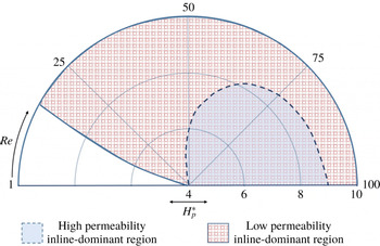
Overall partially filled pin-based MCHS behaviour. High permeability:
 $D_{pin}^{\ast }=1$
; low permeability:
 $D_{pin}^{\ast }=0.5$
.

Variation of friction ratio with respect to
 $Re$
and porous medium height.

It is worth mentioning that the critical point where the heat transfer superiority changes depends not only on the porous medium height, but is also a function of the Reynolds number and the porous medium permeability. Figure 7 summarizes the results derived from multifarious analyses conducted on various systems for different
 $Re$
and permeabilities. For the range of parameters examined, a general pattern emerges for the partially filled pin-based MCHS. For the high-permeability case,
 $D_{pin}^{\ast }=1$
, at
 $4<H_{p}^{\ast }<8.8$
, there is a region in the
 $H_{p}^{\ast }$
–
 $Re$
map where the inline configuration performs better than its staggered counterpart (shaded with continuous blue colour). Accordingly, moving along the
 $H_{p}^{\ast }$
grids in a clockwise direction, there is a critical
 $Re$
above which the inline configuration becomes dominant. This can be simply explained by the fact that at low
 $Re$
, the coolant tends to go through the least-resistance areas, and therefore the inline configuration which has less resistivity is more efficient than the staggered configuration. For larger porous medium heights,
 $H_{p}^{\ast }>8.8$
, however, regardless of the value of
 $Re$
, the staggered configuration outperforms the inline one. It is noteworthy that these analyses have been conducted using a common range of values of the parameters in MCHS studies (Ahmed et al.
Reference Ahmed, Salman, Kherbeet and Ahmed2018).
It is also worth noting that the
 $H_{p}^{\ast }$
–
 $Re$
map changes as the permeability of the porous medium changes. Therefore, the same analyses were carried out for partially filled pin-based MCHS with half-size pins,
 $D_{pin}^{\ast }=0.5$
, with the same reference length. Keeping the porosity constant, the permeability of the porous medium, using the Carman–Kozeny equation, drops by a factor of approximately 4 (Carman Reference Carman1937). As can be observed in figure 7, the inline dominant region, shaded with red dotted grid, expands and covers most of the
 $H_{p}^{\ast }$
–
 $Re$
map. This is expected as the lower-permeability porous medium engenders a stronger resistance for the coolant to enter the pore space, and therefore the coolant tends to bypass the porous medium. In the case of low-permeability porous medium, at high
 $Re$
where inertial forces are dominant, regardless of the porous medium height, the inline configuration, which has less resistivity, outperforms the staggered one.
One may ask what happens at the thermal critical porous medium height/critical Reynolds number where the superiority of the configurations changes. One explanation may be obtained from the friction factor of the porous medium. Figure 8 depicts the variation with
 $Re$
of the friction ratio, defined as the ratio of the friction factor of the staggered configuration to that of the inline one, for different porous medium heights. As can be seen, the friction ratio is always greater than one and it increases with increasing Reynolds number (Xu, Zhao & Vafai Reference Xu, Zhao and Vafai2018). This reflects the fact that as
 $Re$
increases, the staggered configuration becomes more resistant to the coolant flow compared to the inline configuration. Therefore, beyond a critical
 $Re$
, the inline configuration becomes more efficient as it allows the coolant to flow in between the pins. It is also worth mentioning that for any given
 $Re$
, the friction ratio increases as the height of the porous medium increases. This implies that as the height of the porous medium increases, the difference between the staggered and the inline configurations gets larger. This can be explained by the fact that as the porous medium height increases, its contribution to the flow development increases (it acts as a barrier) while the low-resistance areas shrink. As a consequence, the impact of the pin configuration on the efficiency of the MCHS becomes more significant. Hence, for a fixed
 $Re$
, there is a critical porous medium height above which the staggered configuration performance is superior to that of the inline one as the coolant is forced to flow through the porous medium (figure 7). It is worth mentioning that although it may not be straightforward to predict the critical values using the friction factor, there is a noticeable friction ratio increase as seen in figure 8. This sharp increase occurs around the critical porous medium heights
 $(8<H_{p}^{\ast }<10)$
for
 $Re\approx 65{-}100$
(shown by hatched area) where, in spite of only two units increase in
 $H_{p}^{\ast }$
, a noticeable increase can be observed. As one can see from figure 7,
 $H_{pct}^{\ast }$
for this range of
 $Re$
is between
 $8<H_{p}^{\ast }<10$
which confirms the interpretation of the observed friction ratio increase. This increase is, however, less noticeable at lower Reynolds numbers as the flow is slow and the hydrodynamic effects due to the pins are less important.
To shed light on the roles of the porous and non-porous regions, the system is analysed from a hydrodynamic point of view where the flow rates of the porous and non-porous windows at different porous medium heights are calculated at
 $L_{1}^{\ast }+L_{p}^{\ast }$
and illustrated in figure 9. Generally, as the porous medium height increases, the flow rate in the porous medium increases while that in the non-porous windows decreases. This indicates that, regardless of pin configuration, as the porous medium height increases, its contribution to the coolant flow increases up to a point where the coolant flows equally through the porous and non-porous regions. This hydrodynamic critical porous medium height,
 $H_{pch}^{\ast }$
, depends on the pin configuration and the permeability. As can be seen, the critical porous medium height is smaller for the inline configuration compared to the staggered one, and there is a
 $H_{pch}^{\ast }$
gap between the two configurations. This implies that the inline configuration offers less resistance than the staggered one, and hence the porous window flow rate for the inline configuration is higher while the non-porous window flow rate is lower. This gap will be re-examined later, using an analytical approach.
Flow contribution of porous and non-porous windows for inline and staggered configurations;
 $Re=100$
.

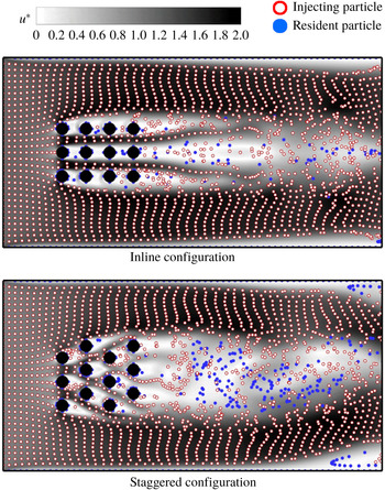
Particle distribution along with the velocity field of the inline and staggered configurations at
 $H_{p}^{\ast }=6,Re=100$
.

It is worth mentioning that the hydrodynamic critical
 $H_{p}^{\ast }$
is larger than the thermal one (see figure 6). This means that before the flow contribution of the porous medium becomes important, its thermal contribution in terms of pin configuration is dominant. The reason is that the porous medium is open at all sides implying that the coolant can enter and exit from the horizontal boundaries of the porous medium as well as the vertical ones. Moreover, since the porous medium offers stronger resistance, it is more plausible to expect the coolant to leave the porous medium through the horizontal surfaces. This implies that the coolant fluid elements are carrying information (high temperature) out of the porous medium before reaching the outlet. Accordingly, the flow rate determined at the porous medium outlet is not necessarily representative of the actual porous medium flow rate and, in fact, determining the flow rate is more involved.
To shed light on this intricacy, a particle tracking study is conducted to analyse the resident and flowing fluid behaviour. To do so, inert, non-reactive solid particles, shown in blue, are initially distributed uniformly in the whole system with a particle number density of
 $\unicode[STIX]{x1D70C}_{N}=2145$
per whole domain. The coolant containing inert, non-reactive hollow particles, shown in red, with the same number density,
 $\unicode[STIX]{x1D70C}_{N}$
, is injected at the entrance. Hence, the hollow particles trace the injecting coolant while the solid ones trace the resident fluid flow behaviour. The particles have no effect on the flow and they travel based on the velocity field in the system, obeying Newton’s law of motion. Figure 10 illustrates the particle distribution along with the velocity field of the inline and staggered configurations for
 $H_{p}^{\ast }=6$
. As can be seen, the hollow particles flow through both the porous and non-porous windows. The particles going through the non-porous window are somehow arranged in a regular layered way while the particles travelling through the porous medium have a rather random distribution. The layered distribution in the non-porous area results from the velocity gradient derived by the viscous boundary layer, meaning that there is no vorticity in these areas. The complex particle distribution passing through the porous medium is, however, due to fluid mixing as a result of the complex porous structure. This particle distribution difference can help in distinguishing between the particles passing through the porous and non-porous media. Based on their distribution, the fluid particles affected by the porous region expand more than the previously defined
 $H_{p}^{\ast }$
, and accordingly the thermal critical
 $H_{p}^{\ast }$
is smaller than the hydrodynamic one.
The distributions of the particles provide valuable information regarding the flow and thermal behaviour of the injecting coolant as well as the resident fluid. It can be observed that the number of solid particles downstream is larger in the staggered configuration compared to the inline one. The rather random distribution of these particles implies that they went through the porous medium, and hence the larger number of solid particles in the staggered configuration indicates that the flow through the porous medium is slower than in the inline configuration. Plots of the velocity in the porous medium confirm higher flow rates in the inline configuration where the hollow particles can easily follow the high-velocity regions in between the pins, therefore displacing the resident particles in the porous medium. Few downstream solid particles in the inline configuration can be attributed to the wakes forming in this area resulting in particle entrapment. It is also noteworthy that, unlike the inline distribution, there are some solid particles at the far end (top and bottom corners) in the staggered configuration. It can be also noticed that there are velocity field deviations in these areas where the velocity drops. This mainstream velocity field deviation in the staggered configuration can be attributed to the uneven distribution of the pins at the horizontal boundaries of the porous medium that causes solid particle entrapments in these slow-flow areas which are bypassed by the hollow particles.
3.3 Analytical approach
In this subsection, a simplified model is developed to help understand the dynamics of this complex system. The region of the flow that will be considered is depicted in figure 11. Only the section of MCHS along the porous medium is considered as it is the bottleneck of the system. It will be assumed that there are no entrance effects, the flow is steady and laminar and the solid boundaries obey the no-slip condition. With these assumptions, the flow in the porous medium will be governed by Darcy’s law while that in the low-resistance areas is of Poiseuille type.
Schematic of the analytical domain.

The total flow rate in the system in the porous and non-porous media is
 $$\begin{eqnarray}\displaystyle Q_{t}=Q_{p}+2Q_{np}={\displaystyle \frac{\unicode[STIX]{x1D705}A_{p}}{\unicode[STIX]{x1D707}}}{\displaystyle \frac{\unicode[STIX]{x0394}P}{L_{p}}}+2\left[{\displaystyle \frac{A_{np}\unicode[STIX]{x0394}P}{12\unicode[STIX]{x1D707}L_{p}}}\left({\displaystyle \frac{H-H_{p}}{2}}\right)^{2}\right], & & \displaystyle\end{eqnarray}$$
where
 $Q_{p}$
and
 $Q_{np}$
are the porous and non-porous flow rates while
 $A_{p}$
and
 $A_{np}$
are, respectively, the cross-sectional area of the porous and non-porous parts of the microchannel which can be estimated by
 $H_{p}$
and
 $(H-H_{p})/2$
, respectively. The parameter
 $\unicode[STIX]{x1D705}$
is the permeability of the porous medium and
 $\unicode[STIX]{x0394}P=P_{in}-P_{out}$
is the pressure difference across the domain. Considering unit value in the third dimension and expressing the total flow rate as
 $Q_{t}=UH$
, the dimensionless pressure drop is
 $$\begin{eqnarray}\displaystyle \unicode[STIX]{x0394}P^{\ast }={\displaystyle \frac{H^{\ast }L_{p}^{\ast }}{Re\left[DaH_{p}^{\ast }+{\displaystyle \frac{(H^{\ast }-H_{p}^{\ast })^{3}}{48}}\right]}}. & & \displaystyle\end{eqnarray}$$
In the above expression,
 $Da=(\unicode[STIX]{x1D705}/D_{pin}^{2})$
is the dimensionless porous medium permeability, known as the Darcy number, and is an unknown parameter. It can however be estimated using the Carman–Kozeny equation (Carman Reference Carman1937)
 $$\begin{eqnarray}\displaystyle Da={\displaystyle \frac{\unicode[STIX]{x1D719}^{3}}{36K_{0}(1-\unicode[STIX]{x1D719})^{2}}}, & & \displaystyle\end{eqnarray}$$
where
 $K_{0}$
is the Carman–Kozeny constant that for a bundle of uniform parallel capillary tubes can be approximated by 4.1667 (Ergun Reference Ergun1952) resulting in
 $Da\approx 0.09$
. Hence, this will be adopted for the inline configuration permeability. The pressure drop across the void space regions is determined using the Poiseuille approximation.
Figure 12 compares the variation of the dimensionless pressure drop across the whole system from the analytical and numerical solutions. As one can see, the pressure drop trends as predicted by the simplified analytical model and those from the nonlinear simulations are similar. The relative error is small at low
 $Re$
, and increases as the Reynolds number increases. Clearly the complex hydrodynamic behaviour cannot be represented at larger
 $Re$
by the simplified model, though the general trends are well captured. This is expected since the model solution assumes laminar flow with no entrance effects and no vorticity. These assumptions may be violated at higher Reynolds numbers where the hydrodynamic length increases and some vorticities appear in the flow distribution (see figure 2).
Comparison of dimensionless pressure drop variation using analytical and numerical approaches, inline configuration,
 $H_{p}^{\ast }=14$
.

The simplified model can be also used to determine the variation of the friction factor with the porous medium height. Using the Carman–Kozeny equation which accounts for tortuosity,
 $Da$
in the inline configuration will be 2.25 times that in the staggered one. Figure 13 depicts the variation of the ratio of the friction factor of the staggered configuration over that of the inline one, with the porous medium height at two different permeabilities. The ratio of one for small heights implies that both configurations induce the same resistance to flow. This ratio starts however to deviate from unity around a certain value of
 $H_{p}^{\ast }$
. This deviation corresponds to flows where the coolant is forced to pass through the porous medium resulting in the staggered configuration performing better than the inline one. As such, this change of trends can be related to the hydrodynamic critical porous medium height reported in the numerical simulations, and the friction factor increase observed in figure 8. Furthermore, the deviation takes place at a larger height for the smaller-permeability porous medium. This indicates that the engagement of the staggered configuration occurs at very large porous medium height, and below this height, the flow tends to bypass the porous medium. This trend is also analogous to what was reported in the numerical solutions where the inline dominant region expands for low-permeability cases (see figure 7).
Friction ratio variation with porous medium height at two different permeabilities, analytical approach.

It is worth mentioning that, unlike the numerical approach, the analytical model is unable to predict the friction ratio at different Reynolds numbers as it ignores the convective terms. The flow rates in porous and non-porous regions can, however, still be determined using equations (3.1)–(3.3). Figure 14 illustrates the percentage of the flow passing through the porous and non-porous windows for inline and staggered configurations. Clearly the trends are the same as in figure 9, where the flow rate of the porous medium increases as
 $H_{p}^{\ast }$
increases, while that of the non-porous window decreases. The flow rate in the porous region for the inline configuration is larger than that for the staggered one while the opposite is true for the non-porous region. Similar to the numerical simulation predictions, there is a
 $H_{pch}^{\ast }$
gap between the inline and staggered configurations. Although the critical porous medium heights obtained here with the analytical approach are slightly greater, the gap size is almost the same for both approaches.
Flow contribution of porous and non-porous windows for inline and staggered configurations, analytical solution.

The hydrodynamic
 $H_{pch}^{\ast }$
occurs at the point where the flow rates of the porous and non-porous sections become equal. Therefore, equating these flow rates, the
 $H_{pch}^{\ast }$
is
 $$\begin{eqnarray}\displaystyle H_{pch}^{\ast }=2\unicode[STIX]{x1D6F9}-8Da\unicode[STIX]{x1D6F9}+H^{\ast },\quad \unicode[STIX]{x1D6F9}=(-3H^{\ast }Da+\sqrt{9H^{\ast 2}Da^{2}+64Da^{3}})^{1/3}, & & \displaystyle\end{eqnarray}$$
where
 $Da$
can be the Darcy number of either inline or staggered configuration. This clearly shows the nature of the dependence of the critical hydrodynamic porous medium height on the channel height and porous medium permeability. This dependence can be formulated in terms of one single independent variable
 $\hat{Da}=(Da/H^{\ast 2})$
, henceforth referred to as the scaled Darcy number:
 $$\begin{eqnarray}\displaystyle {\displaystyle \frac{H_{pch}^{\ast }}{H^{\ast }}}={\displaystyle \frac{H_{pch}}{H}}=2f(\hat{Da})-{\displaystyle \frac{8\hat{Da}}{f(\hat{Da})}}+\!1,\quad f(\hat{Da})\!=\!\left(\!-3\hat{Da}+\!\sqrt{9\hat{Da}^{2}\!+64\hat{Da}^{3}}\right)^{1/3}.\qquad & & \displaystyle\end{eqnarray}$$
This result shows that the relationship between
 $H_{pch}^{\ast },H^{\ast }$
and
 $Da$
can be scaled in one curve as shown in figure 15. It is worth mentioning that the above relationship is actually a relationship between
 $H_{pch}/H$
and
 $\unicode[STIX]{x1D705}/H^{2}$
indicating a scaling independent of
 $D_{pin}$
.
Critical hydrodynamic porous medium height variation with respect to scaled Darcy number.

A thermal analysis of the system can also provide valuable information regarding the behaviour of the MCHS at different porous medium heights. Determining the critical thermal porous medium height is, however, more complicated than the hydrodynamic one as it depends on both the flow and thermal behaviours. In order to analyse the system, the Nusselt number of the porous and non-porous sections will be used to determine
 $H_{pct}^{\ast }$
. The Nusselt number is usually correlated as (Bergman et al.
Reference Bergman, Incropera, DeWitt and Lavine2011)
 $$\begin{eqnarray}\displaystyle Nu=\unicode[STIX]{x1D709}Re^{m}Pr^{n}, & & \displaystyle\end{eqnarray}$$
where
 $m$
and
 $n$
are constants and
 $\unicode[STIX]{x1D709}$
is a function of the porous medium structure. For low
 $Re$
, the Nusselt number of porous medium,
 $Nu_{p}$
, for the isothermal boundary condition can be estimated as (Khan, Culham & Yovanovich Reference Khan, Culham and Yovanovich2006)
 $$\begin{eqnarray}\displaystyle Nu_{p}=\unicode[STIX]{x1D709}Re^{1/2}Pr^{1/3}, & & \displaystyle\end{eqnarray}$$
where
 $\unicode[STIX]{x1D709}$
is determined for inline and staggered configuration as follows:
 $$\begin{eqnarray}\displaystyle \unicode[STIX]{x1D709}=\left\{\begin{array}{@{}ll@{}}{\displaystyle \frac{-0.16+0.6(2l^{\ast })^{2}}{0.4+(2l^{\ast })^{2}}}, & \text{inline}\\ (0.588+0.004(2h^{\ast }))[0.858+0.04(2h^{\ast })-0.008(2h^{\ast })^{2}]^{1/2l^{\ast }}, & \text{staggered}.\end{array}\right. & & \displaystyle\end{eqnarray}$$
Following Rohsenow et al. (Reference Rohsenow, Hartnett and Cho1998), the average Nusselt number of the non-porous section,
 $Nu_{np}$
, is 2.4. Hence, the total average Nusselt number can be estimated using the flow-rate-based weighted average of
 $Nu$
of each section:
 $$\begin{eqnarray}\displaystyle \overline{Nu}={\displaystyle \frac{Q_{np}Nu_{np}+Q_{p}Nu_{p}}{Q_{t}}}. & & \displaystyle\end{eqnarray}$$
Using
 $Pr=1$
and
 $Re=100$
, the variation of the average Nusselt number with the porous medium height is depicted in figure 16. In both configurations,
 $\overline{Nu}$
increases as
 $H_{p}^{\ast }$
increases and there is a critical porous medium height below which
 $\overline{Nu}$
of the inline configuration is larger than that of the staggered one, while the opposite is true when this critical height is exceeded. This is in accordance with the results obtained in the numerical simulations.
Average outlet temperature at the end of the analytical domain for staggered and inline configurations;
 $Da_{inl}=2.25$
,
 $Da_{stg}=0.09$
.

At the critical porous medium height, the average Nusselt number is the same for both configurations,
 $\overline{Nu}_{inl}=\overline{Nu}_{stg}$
. Using equation (3.1), this leads to the following expression for the critical height:
 $H_{pct}^{\ast }$
 $$\begin{eqnarray}\displaystyle {\displaystyle \frac{20Re^{1/2}Pr^{1/3}H_{p}^{\ast }}{(H^{\ast }-H_{p}^{\ast })^{3}}}={\displaystyle \frac{\unicode[STIX]{x0394}P_{inl}-\unicode[STIX]{x0394}P_{stg}}{Da_{stg}\unicode[STIX]{x1D709}_{stg}\unicode[STIX]{x0394}P_{stg}-Da_{inl}\unicode[STIX]{x1D709}_{inl}\unicode[STIX]{x0394}P_{inl}}}, & & \displaystyle\end{eqnarray}$$
where the subscripts
 $inl$
and
 $stg$
stand for inline and staggered, respectively.
The above relationship shows that the critical porous medium height not only depends on the hydrodynamic properties, but also on the porous structure. Since
 $\unicode[STIX]{x0394}P_{inl}<\unicode[STIX]{x0394}P_{stg}$
, a physical solution entails
 $Da_{stg}\unicode[STIX]{x1D709}_{stg}\unicode[STIX]{x0394}P_{stg}-Da_{inl}\unicode[STIX]{x1D709}_{inl}\unicode[STIX]{x0394}P_{inl}<0$
, or equivalently that
 $$\begin{eqnarray}\displaystyle \unicode[STIX]{x1D6FA}_{R}=D_{r}\unicode[STIX]{x1D709}_{r}{\displaystyle \frac{Da_{stg}H_{p}^{\ast }+(H^{\ast }-H_{P}^{\ast })^{3}/48}{Da_{inl}H_{p}^{\ast }+(H^{\ast }-H_{P}^{\ast })^{3}/48}}>1, & & \displaystyle\end{eqnarray}$$
where
 $D_{r}=Da_{inl}/Da_{stg}$
and
 $\unicode[STIX]{x1D709}_{r}=\unicode[STIX]{x1D709}_{inl}/\unicode[STIX]{x1D709}_{stg}$
.
Figure 17 illustrates the variation of
 $\unicode[STIX]{x1D6FA}_{R}$
with
 $H_{p}^{\ast }$
for different
 $\unicode[STIX]{x1D709}_{r}$
. Initially
 $\unicode[STIX]{x1D6FA}_{R}$
is virtually independent of
 $H_{p}^{\ast }$
before undergoing a rapid decrease with increasing
 $H_{p}^{\ast }$
and then levelling off at values less than one at high
 $H_{p}^{\ast }$
. It can also be seen that depending on the porous structure, there are cases, e.g.
 $\unicode[STIX]{x1D709}_{r}=0.3$
, where the inequality is not satisfied and, therefore, there is no critical porous medium height. Generally, the analytical solution reveals that critical points are a strong function of the porous structure and permeability and the properties of the porous medium can be optimized in a way that leads to more efficient and low-cost MCHS systems.
Variation of
 $\unicode[STIX]{x1D6FA}_{R}$
with
 $H_{pct}^{\ast }$
for different
 $\unicode[STIX]{x1D709}_{R}$
;
 $Da_{inl}=2.25$
,
 $Da_{stg}=0.09$
.

Comparison of
 $H_{pct}^{\ast }$
using analytical and numerical solutions.

The solution of equation (3.10) is more complex than the hydrodynamic one as the pressure drop is itself a function of the porous medium height and permeability (see equation (3.2)). Considering
 $Z^{\ast }=H^{\ast }-H_{p}^{\ast }$
, equation (3.10) can be simplified to
 $$\begin{eqnarray}\displaystyle & \displaystyle AZ^{\ast 3}+BZ^{\ast }-BH^{\ast }=0, & \displaystyle\end{eqnarray}$$
 $$\begin{eqnarray}\displaystyle & \displaystyle A=12(Da_{stg}-Da_{inl})-5Re^{1/2}Pr^{1/3}(Da_{stg}\unicode[STIX]{x1D709}_{stg}-Da_{inl}\unicode[STIX]{x1D709}_{inl}), & \displaystyle\end{eqnarray}$$
 $$\begin{eqnarray}\displaystyle & \displaystyle B=240Re^{1/2}Pr^{1/3}Da_{stg}Da_{inl}(\unicode[STIX]{x1D709}_{stg}-\unicode[STIX]{x1D709}_{inl}). & \displaystyle\end{eqnarray}$$
Noting that for the range of parameters used the discriminant
 $\unicode[STIX]{x1D6E5}=(B/A)^{2}\! [\!H^{\ast }/4$
 $+B/(27A)\!]$
is always strictly positive, the only non-trivial real solution is as follows:
 $$\begin{eqnarray}\displaystyle {\displaystyle \frac{H_{pct}^{\ast }}{H^{\ast }}}={\displaystyle \frac{H_{pct}}{H}}=1-\unicode[STIX]{x1D6EC}^{1/3}\left[\left(1+\sqrt{1+\left({\displaystyle \frac{2}{3}}\right)^{3}\unicode[STIX]{x1D6EC}}\right)^{1/3}+\left(1-\sqrt{1+\left({\displaystyle \frac{2}{3}}\right)^{3}\unicode[STIX]{x1D6EC}}\right)^{1/3}\right], & & \displaystyle \nonumber\\ \displaystyle & & \displaystyle\end{eqnarray}$$
where
 $\unicode[STIX]{x1D6EC}=B/2AH^{\ast 2}$
.
Using equation (3.15), the variations of
 $H_{pct}^{\ast }/H^{\ast }$
with
 $Re$
are depicted in figure 18. As can be seen, the analytical solution clearly shows that there is no critical thermal porous medium height at small Reynolds numbers, where
 $H_{pct}^{\ast }/H^{\ast }>1$
, as was predicted by the numerical simulations. Furthermore, although the analytical solution over-predicts
 $H_{pct}^{\ast }$
, the trends are well captured where
 $H_{pct}^{\ast }$
increases with
 $Re$
and the increasing trend levels off at high
 $Re$
. It can be actually shown that in the limit
 $Re\rightarrow 0$
,
 $Z\propto Re^{1/6}$
while
 $Z\propto Re^{0}$
when
 $Re\rightarrow \infty$
.
4 Conclusion
In this study, the hydrodynamic and energy removal efficiencies in partially filled pin-based MCHS are analysed for both inline and staggered pin configurations. Because of the hydrodynamic response of the pins, the flow geometry as well as the energy removal performance were shown to be complicated. It was found that unlike what is already known in the case of fully filled pin-based MCHS, the performance of the staggered pin configuration can actually sometimes be worse than that of the inline one. For small porous medium heights, since the resistance to flow in the staggered configuration is strong, the coolant tends to bypass the porous medium, resulting in smaller rates of heat removal. The severity of this problem diminishes for the inline configuration characterized by lower resistance. As the height of the porous medium increases, the coolant is however forced to flow though the porous window and hence the staggered configuration outperforms the inline one. The qualitative observations were later verified by quantitative analyses and it was shown that there is a thermal critical porous medium height,
 $H_{pct}^{\ast }$
, above which the superiority of the inline over staggered configuration changes. It was also found that this behaviour is dependent on the flow geometry as well as the porous medium properties. Therefore, an overall pattern has been determined for the partially filled pin-based MCHS where the dominance of the inline or staggered configuration can be predicted using the Reynolds number, porous medium height and pin size. It was revealed that at the critical porous medium height, the friction ratio of staggered over inline configuration increases abruptly indicating that the coolant is forced to flow through the porous medium. Furthermore, it was shown that there is a critical hydrodynamic porous medium height,
 $H_{pch}^{\ast }$
, where the flow rates through the porous and non-porous sections are comparable, and this hydrodynamic
 $H_{p}^{\ast }$
is larger than the thermal one. A particle tracing analysis revealed that the actual width of the system affected by the porous medium is larger than
 $H_{p}^{\ast }$
and the aforementioned difference between the hydrodynamic and the thermal-based critical
 $H_{p}^{\ast }$
is related to this phenomenon. The lower porous medium flow rate for the staggered configuration at small
 $H_{p}^{\ast }$
was also confirmed by the particle tracking study. The predictions of the numerical simulations were compared with those obtained from an analytical model based on Poiseuille and Darcy approximations. It was shown that critical hydrodynamic and thermal
 $H_{p}^{\ast }$
are inevitable in such systems, where there is a competition between high- and low-resistivity flow passes in terms of flow rate, and these critical values depend on the porous medium properties. The analytical solution showed that
 $H_{pct}^{\ast }$
is a weak function of
 $Re$
as the Reynolds number increases and there is no thermal critical porous medium height at very small
 $Re$
.
Acknowledgements
The authors would like to acknowledge financial support from Alberta Innovates – Technology Futures (AITF) and the use of computational resources from WestGrid.