I. INTRODUCTION
Polymeric materials have aided in the development of nanostructures and nanomaterials for new and emerging technologies.Reference Hongwei and Huck1 Their wide range of chemical structures, functionalities, morphologies, and ease of processing allow for use in a wide range of nanomaterial applications including nanocomposites,Reference Szleifer and Yerushalmi-Rozen2 drug delivery,Reference Samad, Alam and Saxena3 data storage,Reference Ryan4 organic microelectronics,Reference Mcculloch5 and gradient refractive index optics.Reference Beadie, Shirk, Rosenberg, Lane, Fleet, Kamdar, Jin, Ponting, Yang, Kazmierczak, Hiltner and Baer6 The molecular and chain organization of polymers in confined nanometer space, such as ultrathin films, can result in unique crystalline morphologies.Reference Reiter, Botiz, Graveleau, Grozev, Albrecht, Mourran and Moeller7 At this size scale, the confined space prohibits the isotropic spherulitic growth of the lamellae crystals and instead can produce unique crystal orientations. The two major types of lamellae crystal orientation for confined polymers include “on-edge,” where the polymer chains are aligned parallel to the substrate plane, and “in-plane,” where the polymer chains are aligned perpendicular to the substrate plane. Examples of “on-edge” orientation reported in literature include isotactic polypropylene (iPP),Reference Padden and Keith8 polyethylene,Reference Douzinas and Cohen9–Reference Mellbring, Oiseth, Krozer, Lausmaa and Hjertberg12 polyamide-6 (PA6),Reference Muratoglu, Argon and Cohen13, Reference Mukai, Cohen, Bellare and Albalak14 poly(ethylene naphthalate),Reference Tsuji, Novillo, Fujita, Murakami and Kohjiya15, Reference Zhang, Mukoyama, Hu, Yan, Ozaki and Takahashi16 and poly(ethylene terephthalate) (PET).Reference Durell, MacDonald, Trolley, Wehrum, Jukes, Jones, Walker and Brown17 Some literature examples of “in-plane” orientation include poly(ethylene oxide) (PEO),Reference Zhu, Cheng, Calhoun, Ge, Quirk, Thomas, Hsiao, Yeh and Lotz18, Reference Schonherr and Frank19 isotactic polystyrene (iPS),Reference Sutton, Izumi, Miyaji, Miyamoto and Miyashita20 syndiotactic polypropylene (sPP),Reference Bu, Welch, Ho, Zhou, Jangchud, Eby, Cheng, Hsieh, Johnson and Geerts21 poly(3-hydro-xybutyric acid),Reference Abe, Kikkawa, Iwata, Aoki, Akehata and Doi22 poly(ε-caprolactone) (PCL),Reference Mareau and Prud’homme23, Reference Sun, Chung, Li, Ho, Ko, Jeng and Lotz24 and poly(l-lactide) (PLA).Reference Ho, Lin, Tsai, Lin, Ko, Hsiao and Sics25 Variables that can potentially impact lamellar orientation in confined crystalline polymers include crystallization temperature, film thickness, chain mobility, and substrate/polymer interactions.Reference Wang, Chan, Ng and Li26
Polymer crystallization under one-dimensional (1D) confinement is conventionally studied with a spin-coated thin polymer layer on a substrate,Reference Frank, Rao, Despotopoulou, Pease, Hinsberg, Miller and Rabolt27 with a block copolymer that contains at least one crystallizable block,Reference Zhu, Cheng, Calhoun, Ge, Quirk, Thomas, Hsiao, Yeh and Lotz18 with a deformation of immiscible blends,Reference Li and Kaito28 or with a patterned substrate.Reference Hu, Baralia, Bayot, Gohy and Jonas29 Each of these techniques has specific limitations. Spin-coating and patterned substrates require a solvent during processing, which can limit the choice of polymer. The process itself also produces a small amount of material that contains a free surface, which is known to affect the properties of the polymer thin layer.Reference Wang, Chan, Ng and Li26, Reference Forrest, Dalnoki-Veress, Stevens and Dutcher30 Self-assembly of block copolymers requires specific synthesis, which limits the polymers available for study. The final phase separated block copolymer morphology may not possess long-range order and can require the use of shear alignment to produce a uniformly oriented phase structure.Reference Chen, Kornfield, Smith, Grothaus and Satkowski31 Blending is limited by miscibility of the blended components. Layer-multiplying “forced assembly” coextrusion offers a new approach to study confined crystallization of polymers.Reference Ponting, Hiltner and Baer32 This process can be used to combine two or three polymers into a continuous alternating layered structure with hundreds or thousands of layers with individual layer thicknesses down to 10 nm. This process allows for long range, almost defect-free confinement to study confined polymer crystallization.
In recent years, our interest in confined crystallization in micro- and nanolayered films has led to an exciting opportunity to investigate the structure–property relationships of a wide range of crystalline polymers under true 1D confinement in an effort to establish the generality of this phenomenon using microlayer coextrusion. The determination of the critical factors that control or regulate the observed structure and subsequent properties is useful to guide future research and also to develop potential products that utilize this technology. This review will first address the confined crystallization discovery using layer-multiplying coextrusion with PEO.Reference Wang, Keum, Hiltner, Baer, Freeman, Rozanski and Galeski33 The discussion will also highlight another condensation polymer, PCL, which was found to exhibit similar behavior to PEO when confined in nanolayers against a glassy amorphous polymer such as polystyrene (PS).Reference Ponting, Lin, Keum, Hiltner and Baer34 A detailed discussion of these two systems in the context of the confinement mechanism will follow in regard to polymer interaction, that is, the effect of the confining substrate, the crystallization kinetics, and the temperature effect on the polymer crystal orientation. Section II of this review highlights how the knowledge gained from PEO and PCL was used to study confined crystallization in various chain-growth polymers and their effect on structure and properties.
II. PART I: CONFINED CRYSTALLIZATION OF PEO AND PCL CONDENSATION POLYMERS
A. Section I: Crystal orientation of PEO and PCL in nanolayered films confined by PS
The initial breakthrough of confined crystallization in multilayered films was found when a highly crystalline PEO polymer confined against semicrystalline ethylene acrylic acid (EAA).Reference Wang, Keum, Hiltner, Baer, Freeman, Rozanski and Galeski33 The profound effect of confinement on the PEO led to an anisotropic in-plane, single crystal-like orientation when the individual PEO layer thickness was reduced down to the thickness of an individual PEO lamellae. To gain additional understanding into the material and processing variables that ultimately dictate this observed multilayer confinement process, additional semicrystalline polymers that observe this behavior were sought out. Several polymer properties were identified that may affect the multilayer confinement-induced orientation including relative material crystallinity, melting point, and bulk crystal morphology. PEO possess a relatively high bulk crystallinity of 75% and a melting temperature of 65 °C.Reference Wang, Keum, Hiltner, Baer, Freeman, Rozanski and Galeski35 The bulk crystal habit of PEO is spherulitic with a monoclinic crystal form.Reference Wang, Keum, Hiltner and Baer36, Reference Tadokoro, Chatani, Yoshihara, Tahara and Murahashi37 PCL was identified as a candidate polymer for multilayer confinement studies because of its bulk crystallinity level, 40%, similar melting temperature of 57 °C, bulk spherulitic crystal habit, and similar melt processing temperature. PCL possesses lower crystallinity, 40% compared to 75% for PEO, in addition to lower bulk modulus and thinner individual crystal lamellae, 15-nm thickness compared to 25 nm for PEO.Reference Sun, Chung, Li, Ho, Ko, Jeng and Lotz24, Reference Wang, Keum, Hiltner and Baer36, Reference Iwata and Doi38 This section will review the effect of confined crystallization on the crystal orientation and transport properties of PEO and PCL confined against an amorphous PS layer.
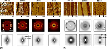
PEO (PolyOx WSR N-80, The Dow Chemical Company, Freeport, TX) and PCL (Capa 6800, Perstorp UK Ltd., Warrinton, UK) were successfully coextruded against PS (Styron 666D or Styron 615APR, The Dow Chemical Company, Freeport, TX) using layer multiplication “forced assembly” coextrusion process as shown in Fig. 1.Reference Ponting, Hiltner and Baer32 The layer thickness of the PEO and PCL was varied from 35 μm down to 20 nm by increasing the total number of layers in the multilayer film from 9 to 1025 layers and by tuning the relative composition of PS/PEO or PS/PCL. This range of layer thicknesses provided an opportunity to compare true 1D confinement of the PEO and PCL crystalline polymers on a size scale comparable to the diameter of a PEO and PCL spherulite (PEO: 160 μm; PCL: 8–10 μm) down to the thickness of an individual PEO and PCL lamellae (PEO: 25 nm; PCL: 15 nm).Reference Sun, Chung, Li, Ho, Ko, Jeng and Lotz24, Reference Wang, Keum, Hiltner and Baer36, Reference Iwata and Doi38, Reference Wang, Keum, Hiltner and Baer39 The morphology and orientation of the confined PEO and PCL crystalline structure were probed as a function of layer thickness using atomic force microscopy (AFM), wide-angle x-ray scattering (WAXS), and small-angle x-ray scattering (SAXS) [Figs. 2(a) and 2(b)].
Layer-multiplying coextrusion for forced assembly of polymer nanolayers. After the polymer melts are combined in the ABA feedblock, the melt stream flows through a series of layer-multiplying die elements; each element splits the melt vertically, spreads it horizontally, and finally recombines it with twice the number of layers. The figure illustrates how two elements multiply the number of layers from 3 to 9. An assembly of n die elements produces 2(n+1)+1. Reprinted with permission from H. Wang, J. K. Keum, A. Hiltner, E. Baer: Crystallization kinetics of poly(ethylene oxide) in confined nanolayers. Macromolecules 43, 3359 (2010). Copyright 2010, American Chemical Society.

(a) Top row: atomic force microscopy (AFM) phase images of partial 1 mm × 1 mm cross sections of polystyrene/poly(ethylene oxide) (PS/PEO) layered films with: 1 μm; 300 nm; 75 nm; and 25 nm PEO layers. The arrows indicate a PEO layer. Extrusion direction wide-angle x-ray scattering (ED WAXS) (middle row) and extrusion direction small-angle x-ray scattering (ED SAXS) (bottom row) patterns of PS/PEO layered films with nominal PEO layer thickness of: 1 μm; 300 nm; 75 nm; and 25 nm. The x-ray beam was aligned along the ED of the layered films. Adapted with permission from H. Wang, J.K. Keum, A. Hiltner, E. Baer: Confined crystallization of PEO in nanolayered films impacting structure and oxygen permeability. Macromolecules 42, 7055 (2009). Copyright 2009, American Chemical Society. (b) Top row: AFM phase images of partial cross sections of PS/poly(ε-caprolactone) (PCL) layered films with: 1.9 μm; 250 nm; and 50 nm PCL layers. The arrows indicate a PCL layer. All AFM images are 2 μm × 2 μm except the 25-nm image, which is 500 nm × 500 nm. ED WAXS (middle row) and ED SAXS (bottom row) patterns of PS/PCL layered films with nominal PCL layer thickness of: 1.9 μm; 250 nm; 50 nm; and 25 nm. The x-ray beam was aligned along the ED of the layered films. Adapted with permission from M. Ponting, Y. Lin, J. K. Keum, A. Hiltner, E. Baer: Effect of substrate on the isothermal crystallization kinetics of confined poly(ε-caprolactone) nanolayers. Macromolecules 43, 8619 (2010). Copyright 2010, American Chemical Society.

AFM is an effective tool when studying polymer nanolayered films. It can be used to determine layer thicknesses and layer uniformity and also to elucidate layer morphology. The micro- and nanolayered morphology of PEO and PCL was investigated under confinement. The morphology of thick, microscale, 21-μm PEO layers resemble truncated spherulites seen in bulk PEO crystallization habit and are primarily nucleated from within the PEO layer (not shown). The effect of PS confinement can already be seen as the PEO layer thickness approaches 1 μm with a transition from three-dimensional (3D) spherulites to two-dimensional (2D) discoids that nucleate at the PS/PEO interface. The radial lamellar growth is constrained in the 1-μm layers by the PS, thereby orienting the growth of the long radial lamellae into the layer plane. In the 300-nm layers, the PEO growth direction is highly constrained by the confining PS layer producing lamellae stacks that are primarily oriented in the layer plane. Further reducing the PEO layer thickness to 75 nm resulted in the PEO crystallizing into stacks of three to five long lamellae with the vast majority oriented in the plane of the layer. Finally, in the 25-nm-thick layers, the PEO crystallized into long, single crystal-like lamellae that were sandwiched in between thick PS layers.
Analysis of the AFM images for the PS/PCL multilayer films reveals that the confined crystallization of PCL produced similar morphological features as previously indicated in PEO even though the relative crystallinity of the PCL was almost half that of PEO. For thick 16-μm PCL layers, 8–10-μm isotropic spherulites were observed (not shown). At 1.9-μm PCL layers, the isotropic spherulitic structure changed to truncated spherulites or discoids that were seen to occasionally nucleate at the PS/PCL interface. Upon further reduction in layer thickness down to 250-nm layers, stacks of PCL lamellae were highly oriented in the plane of the layers. Similar to the PEO system, under the highest degree of layer confinement and layer thickness was reduced down to 50 nm, the PCL layers appeared as long, single crystal-like lamellae with very large aspect ratio. Further investigation and confirmation of the confinement mechanism was carried out using WAXS and SAXS.
X-ray scattering was used to determine the crystal and lamellae orientation of the PEO and PCL confined layers. Two-dimensional WAXS and SAXS patterns were obtained in the extrusion direction (ED) for PS/PEO and PS/PCL multilayer films with individual layer thicknesses ranging from 21 μm to 25 nm. Similar features were observed for both systems. On the microscale, both PEO and PCL showed evidence of confinement indicated by the appearance of equatorial crystal reflection arcs, PEO (120) plane and PCL (110) and (200) planes, for the WAXS patterns and a concentration of intensity at the meridian in the SAXS patterns. For WAXS, the presence of hk0 reflections at the equator confirmed that the chain axis was perpendicular to the layers, thus forming an in-plane crystal orientation. As the layer thickness was decreased to the nanoscale for both systems, the intensity and sharpness of meridional reflections of the SAXS patterns increased, indicating a high level of lamellar orientation in the plane of the layers. The crystal orientation was also improved at the nanoscale as evidenced by the sharpening of the equatorial reflection arcs in the WAXS images for both systems. Finally, when the layer thickness was comparable to the thickness of PEO and PCL lamellae, the SAXS meridional intensity was reduced for both systems, indicating the inability of the crystal lamellae to stack, thus forming a single, in-plane, high aspect ratio lamellae crystal. The WAXS patterns also confirm this observation with the appearance of spot (120) reflections for PEO resembling a PEO fiber patternReference Takahashi and Tadokoro40 and very sharp (110) and (200) arc reflections for PCL. This observation proved that the crystallization of confined crystalline nanolayers as large in plane lamellae was a generalized phenomena and was not unique to PEO. The generality between PEO and PCL could be linked to their linear chain structures, both of which contain ether linkages, in addition to the similar thermal properties and high crystallinity.
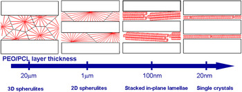
As demonstrated, confined crystallization under nanolayer confinement has produced anisotropic crystal orientations for both PEO and PCL confined against a hard, amorphous, PS layer. Both systems show remarkable similarities in their structure as the layer thickness is reduced from the microscale to the nanoscale, even though there are distinct differences in both the bulk crystallinity and the lamellae thickness of PEO and PCL. Based on the morphology (AFM) and structure data (x-ray) for these systems, the structure evolution of the two polymers as a function of layer thickness is summarized in Fig. 3.
Structure/morphology evolution of PEO and PCL confined layers as the layer thickness is reduced from the microscale to the nanoscale.

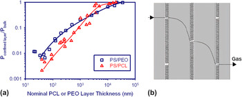
Structure–property effects from the morphological shift in confined crystalline polymer layer architecture were examined with oxygen permeability measurements. The polymer crystalline phase is generally regarded as impermeable to small gas molecules, resulting in gas transport occurring through the amorphous phase.Reference Weinkauf, Paul and Koros41 A result of PEO or PCL confined crystallization is the formation of an in-plane crystal morphology, which should have a tremendous impact on gas transport properties because of the high aspect ratio and high crystallinity levels of both PEO and PCL. The oxygen permeability of PS/PEO and PS/PCL films was measured in a Mocon OxTran (Minneapolis, MN) permeability unit at 25 °C and no relative humidity. The effective PEO and PCL permeability as a function of layer thickness was calculated from the measured oxygen flux using the series transport model for layered structures and normalized by the permeability of the bulk material as shown in Fig. 4(a).Reference Ponting, Lin, Keum, Hiltner and Baer34, Reference Wang, Keum, Hiltner and Baer36
(a) Effective permeability of the confined layer normalized by the permeability of the bulk material as a function of nominal layer thickness for both PS/PEO and PS/PCL multilayered films. Adapted with permission from H. Wang, J.K. Keum, A. Hiltner, E. Baer: Confined crystallization of PEO in nanolayered films impacting structure and oxygen permeability. Macromolecules 42, 7055 (2009). Copyright 2009, American Chemical Society. Adapted with permission from M. Ponting, Y. Lin, J. K. Keum, A. Hiltner, E. Baer: Effect of substrate on the isothermal crystallization kinetics of confined poly(ε-caprolactone) nanolayers. Macromolecules 43, 8619 (2010). Copyright 2010, American Chemical Society. (b) Schematic of gas diffusion pathway through nanolayered PEO and PCL confined by PS. From H. Wang, J. K. Keum, A. Hiltner, E. Baer, B. Freeman, A. Rozanski, A. Galeski: Confined crystallization of polyethylene oxide in nanolayer assemblies. Science 323, 757 (2009). Reprinted with permission from AAAS.

Above a 10-μm layer thickness, the structure of both PEO and PCL is consistent with a traditional 3D spherulitic morphology with little effect of layer confinement and thus resulting in little to no enhancement in oxygen barrier properties. As the layer thickness was reduced below 10 μm, a decrease in effective permeability of PEO and PCL confined layers compared to the bulk materials was observed. At 1-μm thick layers, the crystal morphology of both PEO and PCL resembled 2D discoids and possessed an effective permeability value almost 10 times lower than the bulk materials. Further reducing the layer thickness into the nanoscale where the intralayer PEO or PCL morphology consisted of stacked lamellae, considerable enhancement in the barrier properties was measured. At layer thicknesses around 20–30 nm, barrier properties were almost 150–300 times lower than the bulk PEO and PCL permeability.
Since the PEO and PCL lamellae crystalline core is impermeable to gas, the diffusion mechanism of oxygen through the film would occur at defects between lamellae crystals in the amorphous regions. The frequency of these defects between the in-plane lamellae would ultimately determine the diffusion pathway and subsequent gas barrier performance.Reference Weinkauf, Paul and Koros41 Considering the in-plane lamellae as a dispersion of impermeable platelets with a given aspect ratio, which are primarily oriented perpendicular to the gas flux, the average aspect ratio can be estimated using the Cussler model.Reference Wang, Keum, Hiltner, Baer, Freeman, Rozanski and Galeski33, Reference Cussler, Hughes, Ward and Aris42 The aspect ratio of the PEO and PCL crystals, defined as the length divided by the thickness, can be calculated knowing the overall film permeability, PEO and PCL crystallinity, and overall film density while assuming that the permeability of the confining layer does not change with layer thickness. The lateral size of the PEO and PCL crystals can then be determined knowing the thickness of an individual lamellae measured by SAXS (PEO: 23 nm; PCL: 6 nm).Reference Ponting, Lin, Keum, Hiltner and Baer34, Reference Wang, Keum, Hiltner and Baer36, Reference Cussler, Hughes, Ward and Aris42 The lateral size of the in-plane lamellae crystals estimated from the Cussler model range from 1.5 to 5 μm for PEO and 0.75 to 1.6 μm for PCL. The AFM images confirmed that these aspect ratios were reasonable for both PEO and PCL. This very large improvement in oxygen barrier properties was attributed to the large, in-plane single crystal PEO and PCL morphologies induced through nanolayer confinement, which increased the tortuosity of gas diffusion through the film [Fig. 4(b)]. Additionally, other variables from the Cussler model that could contribute to the decreased gas diffusion in these systems include the defect site or slit aspect ratio and geometric variations in lamellae or plate size.Reference Cussler, Hughes, Ward and Aris42
1. Effect of crystallization and quench conditions
Confining PEO and PCL against PS provides an interesting opportunity to study the crystallization habit and confinement mechanism of the confined polymers as determined by the temperature dependence of the nucleation and growth processes. A temperature window exists between the relative low melting points of PEO and PCL (T m,PEO = 65 °C; T m,PCL = 57 °C) and the T g of PS (T g,PS = 95 °C), which allows for isothermal recrystallization or quench experiments, where the PEO or PCL layers can be melted and recrystallized/quenched under rigid 1D confinement from the PS layer. This temperature window allows access to the temperature domain for the PEO and PCL crystallization. It is important to note that the T g of PS confined in nanolayers closely matched the value obtained for the bulk PS sample, indicating very little interphase material is present.
Utilizing this temperature window, both PS/PEO and PS/PCL samples with 20- to 50-nm PEO or PCL layer thicknesses were held isothermally at 85–90 °C, well above each respecting polymer T m, to melt the confined polymer and subsequently cooled at 10 °C/min. Both PEO and PCL exhibited crystallization exotherms, which were only slightly lower than the bulk samples (T c, PEO-Bulk = 45 °C versus T c, PEO-25nm = 40 °C; T c, PCL-Bulk = 30 °C versus T c,PCL-50nm = 26 °C).Reference Ponting, Lin, Keum, Hiltner and Baer34, Reference Wang, Keum, Hiltner and Baer36 The T c for the confined PEO and PCL was much higher than the reported temperatures for homogeneous nucleation (PEO: −10 to 0 °CReference Massa and Dalnoki-Veress43, Reference Koutsky, Walton and Baer44; PCL: −45 to -50 °CReference Muller, Balsamo, Arnal, Jakob, Schmalz and Abetz45); therefore, it was concluded that the crystallization of both PEO and PCL nanolayers nucleated on heterogeneous nuclei, such as catalyst residues, high molecular weight gel particles, or dust particles.
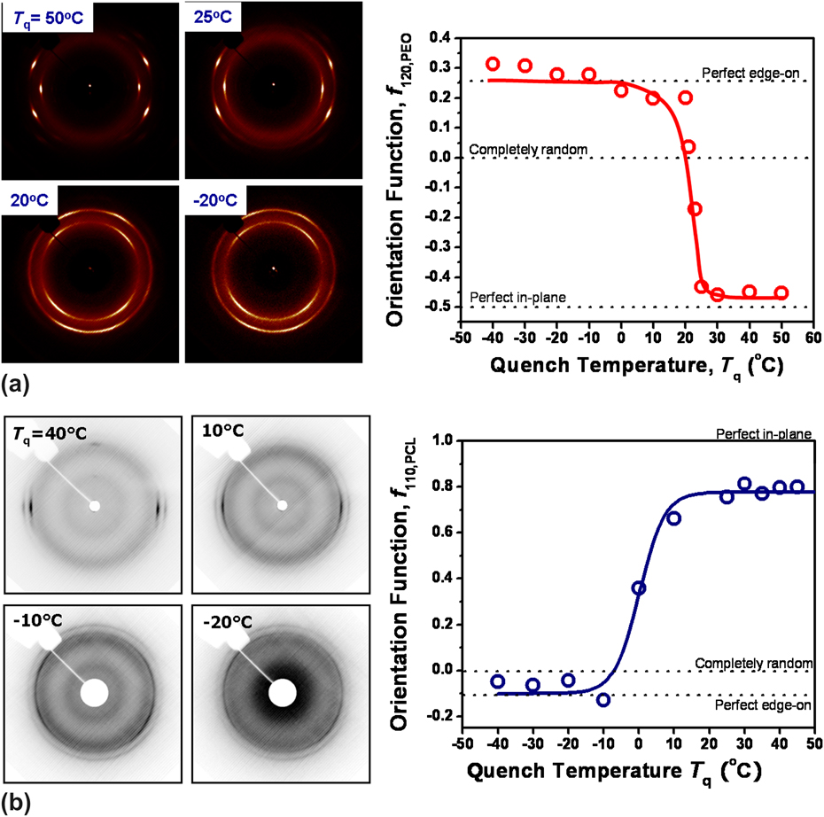
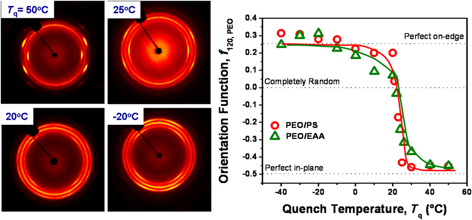
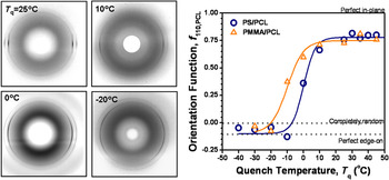
For both PS/PEO and PS/PCL nanolayered films, the temperature-dependent activation of heterogeneous nuclei was studied by first melting the confined polymer under the hard confinement of PS and quenching to various temperatures T q.Reference Wang, Keum, Hiltner and Baer46 ED WAXS patterns of these films with different T q were measured and used to quantitatively describe the PEO and PCL crystal orientation using Hermans orientation functionReference Hermans47, Reference Wang, Keum, Hiltner and Baer48 [Figs. 5(a) and 5(b)]. To compare the degree of crystal orientation at different T q, the Hermans orientation function was calculated for the PS/PEO and PS/PCL systems by using the azimuthal intensity distributions of the PEO (120) reflection and PCL (110) reflection measured on the ED WAXS pattern. By definition for PEO, an orientation function f 120 = −0.5 indicates the normal of the (120) plane is perpendicular to the layer normal, and for f 120 = 0, the crystal orientation is completely isotropic or random. For PCL, an orientation function f 110 = 1 indicates the normal of the (110) plane is perpendicular to the layer normal, and for f 110 = 0, the crystal orientation is completely isotropic or random.
(a) ED WAXS patterns for PS/PEO nanolayered films with 75-nm PEO layer thickness quenched at various T q. Herman’s orientation function PEO f 120 as a function of quench temperature indicating the sharp transition in PEO crystal orientation from in-plane to edge-on as T q is decreased. Adapted with permission from H. Wang, J. K. Keum, A. Hiltner, E. Baer: Supporting information for Impact of nanoscale confinement on crystal orientation of poly(ethylene oxide). Macromol. Rapid Commun. 31, 356 (2010). Copyright 2010, John Wiley and Sons. (b) ED WAXS patterns for PS/PCL nanolayered films with 40-nm PCL layer thickness quenched at various T q. Herman’s orientation function PCL f 110 as a function of quench temperature indicating the sharp transition in PCL crystal orientation from in-plane to edge-on as T q is decreased.

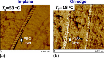
Changing T q for both the PS/PEO and PS/PCL systems showed dramatic effects on the confined crystal orientation. For both systems at low T q, the confined polymers crystallize into an on-edge lamellae orientation. As the quench temperature was increased, there exists a transition region where the PEO and PCL go from on-edge to in-plane lamellae orientation. This temperature range is particularly sharp for PEO, between T q = 0 to 25 °C, and occurred over a similar magnitude temperature range for PCL, T q = −10 to 10 °C. For both systems, the crystallization or quenching temperature is paramount for controlling the crystal orientation of the confined layer. The transition from on-edge to in-plane lamellae orientation with increased ambient temperature also suggests a strong kinetic dependence on the confined layer orientation. On-edge lamellae crystals have been observed in PS-b-PEO block copolymers and were determined to be homogenously nucleated at temperatures ranging from −10 to 0 °C.Reference Massa and Dalnoki-Veress43, Reference Koutsky, Walton and Baer44, Reference Hsiao, Zheng, Leng, Van Horn, Quirk, Thomas, Chen, Hsiao, Rong, Lotz and Cheng49, Reference Huang, Zhu, Guo, Ge, Jing, Chen, Quirk, Cheng, Thomas, Lotz, Hsiao, Avila-Orta and Sics50 In confined nanolayers, the on-edge lamellae orientation was produced for both PEO and PCL well above the homogenous nucleation temperature for PEO and PCL as indicated above. This suggests that the confining substrate plays a critical role and assists the nucleation of the on-edge crystal orientation.Reference Bartczak, Argon, Cohen and Kowalewski11 Since lattice matching is not possible with an amorphous PS substrate, it is speculated that there is some preferential chain orientation at the interface, which facilitates homogenous nucleation. This results in a higher temperature for homogeneous nucleation that is seen in the multilayered films. It is important to note that this chain orientation at the interface is not possible using block copolymers because of the crowding imposed by the covalent bonds. Potential substrate nucleation effects were hypothesized to be deactivated at higher T q resulting in heterogeneously nucleated, in-plane lamellae growth of the confined polymer. Representative examples of different PEO morphologies obtained at two different T q are shown in Fig. 6. The AFM images clearly show two distinct PEO lamellae crystal orientations, in-plane and on-edge, which can be controlled by adjusting the T q.
1 μm × 1 μm AFM images of PS/PEO nanolayered films with 75-nm PEO layer thickness. (a) Left image was melted at 90 °C and quenched to 53 °C producing in-plane PEO lamellae oriented parallel to the layers. Adapted with permission from H. Wang, J. K. Keum, A. Hiltner, E. Baer: Crystallization kinetics of poly(ethylene oxide) in confined nanolayers. Macromolecules 43, 3359 (2010). Copyright 2010, American Chemical Society. (b) Right image was melted at 90 °C and quenched to 18 °C producing on-edge PEO lamellae oriented perpendicular to the layers. Adapted with permission from H. Wang, J. K. Keum, A. Hiltner, E. Baer: Impact of nanoscale confinement on crystal orientation of poly(ethylene oxide). Macromol. Rapid Commun. 31, 356 (2010). Copyright 2010, John Wiley and Sons.

2. Isothermal crystallization kinetics
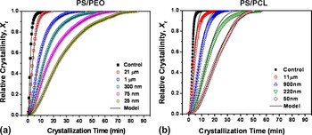
The crystallization and growth of PEO and PCL in-plane lamellae under hard confinement can be studied utilizing the temperature window between the melting point of PEO and PCL and the T g of the confining PS layer discussed previously. This study allowed determination of the PEO and PCL kinetics habit of in-plane lamellae under confinement vis-à-vis bulk materials. As previously mentioned, the crystallization of both PEO and PCL in-plane lamellae nucleated on heterogeneous nuclei as determined by differential scanning calorimetry (DSC). Isothermal crystallization kinetics were determined for the PS/PEO and PS/PCL nanolayered systems as a function of layer thickness. Both polymers were first melted under hard confinement, T q < T g,PS, within the temperature window described above and recrystallized at high temperatures, T x,PEO = 53 °C, T x,PCL = 40 °C, to produce in-plane lamellae in nanolayers. The relative crystallinity of PEO and PCL was determined by DSC as a function of time and plotted for a range of layer thicknesses including the bulk materials (Fig. 7). Both systems showed that the overall crystallization rate was retarded as the layer thickness was decreased. For example, the crystallization half times, t 1/2, for the PS/PEO system went from t 1/2 = 2 min in bulk PEO to t 1/2 = 21 min in 25 nm PEO layers. For the PS/PEO system, using classical heterogeneous nucleation theoryReference Wunderlich51 and comparing the crystallization half time, t 1/2, with the thermal driving force for isothermal crystallization, (1/T xΔT), a common slope of 5.2 ± 0.15 × 10⁴ was found between the various PEO layer thicknesses and the bulk materialsReference Wang, Keum, Hiltner and Baer39 (not shown). The product of the specific side and fold surface free energies (σσe) was extracted from this slope to be 3.1 × 10⁻⁴ J2/m4, which compared very well with reported literature values for bulk PEO.Reference Wunderlich51, Reference Vyazovkin, Stone and Sbirrazzuoli52 This indicated that the geometric constraint from the nanolayer confinement did not alter the crystallization mechanism and thus followed conventional chain folding crystallization habit.
(a) Relative crystallinity of PEO layers (Xt) versus crystallization time (t) for isothermal crystallization at 53 °C. Adapted with permission from H. Wang, J. K. Keum, A. Hiltner, E. Baer: Crystallization kinetics of poly(ethylene oxide) in confined nanolayers. Macromolecules 43, 3359 (2010). Copyright 2010, American Chemical Society. (b) Relative crystallinity of PCL layers (Xt) versus crystallization time (t) for isothermal crystallization at 40 °C. Adapted with permission from M. Ponting, Y. Lin, J. K. Keum, A. Hiltner, E. Baer: Effect of substrate on the isothermal crystallization kinetics of confined poly(ε-caprolactone) nanolayers. Macromolecules 43, 8619 (2010). Copyright 2010, American Chemical Society.

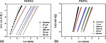
The classic Avrami theory is commonly used to describe any type of crystallization including polymers.Reference Escleine, Monasse, Wey and Haudin53 It can provide information regarding the crystallization kinetics in addition to the nucleation and growth mechanisms.Reference Escleine, Monasse, Wey and Haudin53, Reference Gedde54 The crystallization data for PS/PEO and PS/PCL was plotted according to classic Avrami theory as shown in Fig. 8. The Avrami exponent, n, and crystallization rate constant, k, were extracted from the linear portion of the curve, Xt = 0.05 and Xt = 0.5, for both systems. Confining both PEO and PCL against PS in 25–50-nm layers decreased the crystallization rate constant, k, by over one order of magnitude compared to the bulk materials.Reference Ponting, Lin, Keum, Hiltner and Baer34, Reference Wang, Keum, Hiltner and Baer39 The Avrami exponent, n, describing the crystal growth geometry took an integer value in the 20–50-nm confined layers of 2.0 indicative of 2D crystal growth for both PS/PEO and PS/PCL systems. It was interesting that the confinement of both PEO and PCL greatly suppressed the crystallization kinetics and reduced the Avrami exponent even with PEO and PCL layer thicknesses in the microscale. This behavior can be correlated to the PEO and PCL layer morphologies determined from the AFM. As discussed previously, truncated spherulites were observed in 1-μm-thick PEO and PCL layers. This restricted growth of PEO and PCL under layer confinement could result in the decrease in both the crystallization rate constant and the Avrami exponent seen experimentally. To help describe this observed behavior, the crystallization kinetics of both confined PEO and PCL micro- and nanolayers were modeled considering the effect of truncation on spherulitic growth. Haudin and coworkers have developed a model for the crystallization kinetics of thin polymer films in the microscale by considering truncation when the growing spherulite encounters an interface.Reference Escleine, Monasse, Wey and Haudin53 This model predicts substantial reductions in both the crystallization rate and Avrami exponent when the film thickness is less than the average size of the spherulite and was used to model the behavior of confined PEO and PCL in nanolayers. From the isothermal crystallization data, the radial growth rate of the spherulite, G 0, and the number of potential nuclei per unit volume, N V, were determined for the bulk PEO and PCL control samples using the Haudin model. To model the layered samples, the values of G 0 and N V for the bulk controls were used and the nominal layer thickness of PEO and PCL was taken as d; however, these model parameters predicted a crystallization rate that was much slower than what was observed experimentally for the confined PS/PEO and PS/PCL systems. To accurately model the crystallization data of the confined layered samples, G 0 was held constant and N V was adjusted to give the best fit to the data. The resulting N V increased systematically with decreasing layer thickness for both PS/PEO and PS/PCL systems. This increase in N V was accounted for by considering diffusion of additional heterogeneous nuclei from the PS layer. Commercial PS resins contain numerous thermal and UV stabilizers at relatively high concentrations, which could diffuse to the layer interface during melt processing and effectively increase N V. This was verified experimentally by blending a common PS processing additive, zinc stearate, into bulk PCL at a concentration of 0.1% and determining the crystallization kinetics of the PCL + additive in addition to a PCL blended control.Reference Ponting, Lin, Keum, Hiltner and Baer34 Indeed the PCL compounded with additives displayed a faster crystallization rate compared to the clean PCL sample with no change in the Avrami exponent of 3. From N V, the area density of nuclei was determined by N A = N Vd, for both PS/PEO and PS/PCL systems. Even though N V increased as a function of decreasing layer thickness, N A decreased by an order of magnitude. Decreasing N A as a function of layer thickness would facilitate the formation of large, oriented lamellae that was seen in nanometer confined PEO and PCL layers.
(a) Avrami plots for isothermal crystallization of PEO at 53 °C. Adapted with permission from H. Wang, J. K. Keum, A. Hiltner, E. Baer: Crystallization kinetics of poly(ethylene oxide) in confined nanolayers. Macromolecules 43, 3359 (2010). Copyright 2010, American Chemical Society. (b) Avrami plots for isothermal crystallization of PCL at 40 °C. Adapted with permission from M. Ponting, Y. Lin, J. K. Keum, A. Hiltner, E. Baer: Effect of substrate on the isothermal crystallization kinetics of confined poly(ε-caprolactone) nanolayers. Macromolecules 43, 8619 (2010). Copyright 2010, American Chemical Society. For both plots the solid lines represent the fits from the Haudin model.

Many factors that affect the crystallization of polymers in confined space have been described in the literature. It has been observed that substrates have a profound effect on controlling crystal orientation during crystallization of polymer droplets on substratesReference Damman, Coppee, Geskin and Lazzaroni55 while the surface roughness of the substrate can impact the crystal nucleation.Reference Carvalho and Dalnoki-Veress56 In bulk polymer films, Chatterjee and coworkers have demonstrated the impact of the substrate on the morphologies and crystallization of polymers from the melt.Reference Chatterjee and Price57–Reference Chatterjee and Price59 Here, numerous polymer substrates can effectively nucleate and transcrystallize a wide variety of polymers from the melt independent of chemical structure similarities, crystallographic unit cell type/dimensions, and surface energy. The crystallization habit of these polymers can also be changed depending on the recrystallization temperatures. In substrate-supported ultrathin films, Wang et al. have demonstrated the importance of crystallization temperature, film thickness, chain mobility, and substrate/polymer interactions as important parameters that impact the lamellar orientation in crystalline polymers.Reference Wang, Chan, Ng and Li26 These studies provide insight into some of the critical variables that may dictate the confined crystallization of PEO and PCL in nanolayered films. The next section will focus on our efforts to understand these critical variables and how they impact the observed structure and properties using both PEO and PCL. Specific variables to be studied include confining substrate effect (semicrystalline versus amorphous) and the effect of amorphous substrate interaction parameter.
B. Section II: Effect of confining substrate on crystallization of PEO and PCL in multilayered films
1. PEO: Crystalline versus amorphous confining substrates
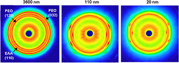
In addition to PS, other confining polymers have been utilized to successfully confine semicrystalline PEO in multilayered films. This section reviews the effect of semicrystalline and amorphous substrates as confining layers on the crystal orientation of PEO in addition to the oxygen barrier properties. As indicated previously, PEO was initially confined against a semicrystalline poly(ethylene-co-acrylic acid) (EAA) polymer with 9.7 wt% acrylic acid content and 34% relative crystallinity (Primacor 1410, The Dow Chemical Company, Freeport, TX).Reference Wang, Keum, Hiltner, Baer, Freeman, Rozanski and Galeski35 Similar to the PS/PEO system, the EAA/PEO system produced an anisotropic PEO in-plane crystal morphology when the PEO layer thickness was reduced to the nanoscale (Fig. 9). ED WAXS images of the EAA/PEO system clearly show the in-plane orientation of the PEO crystals at 20-nm PEO layer thickness indicated by the appearance of the equatorial PEO (120) reflection arcs, which resemble spots similar to the PS/PEO system. The WAXS patterns show an additional reflection ring corresponding to the EAA (110) plane, which exhibited no significant layer thickness dependent orientation of the EAA crystals as a result of nanolayer confinement.
ED WAXS patterns of ethylene acrylic acid (EAA)/PEO multilayered films with nominal PEO layer thickness of 3.6 μm, 110 nm, and 20 nm. The x-ray beam was aligned along the ED of the layered films. From H. Wang, J. K. Keum, A. Hiltner, E. Baer, B. Freeman, A. Rozanski, A. Galeski: Supporting information for Confined crystallization of polyethylene oxide in nanolayer assemblies. Science. 323, 757 (2009). Reprinted with permission from AAAS.

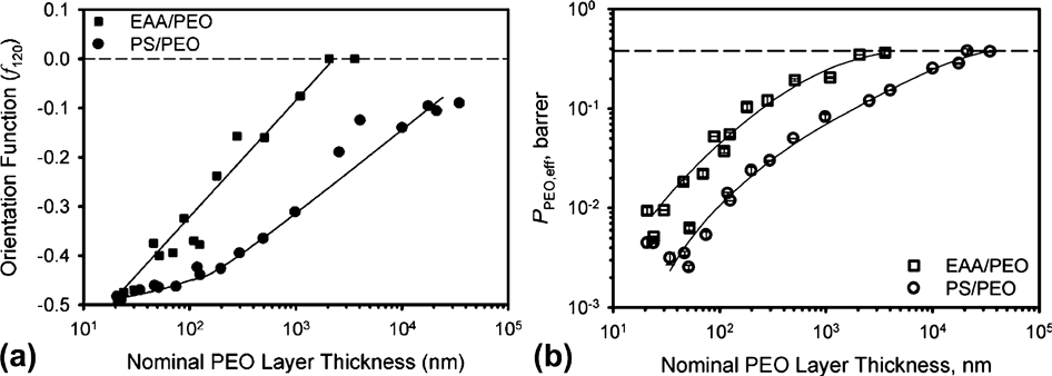
Although the morphology was consistent with what was observed in the PS/PEO system, careful inspection of the degree of orientation and oxygen permeability properties revealed differences when the PEO was confined by PS or EAA (Fig. 10). To compare the degree of crystal orientation, the Herman’s orientation function was calculated for the EAA/PEO and PS/PEO systems by using the azimuthal intensity distributions of the PEO (120) reflection measured on the ED WAXS pattern.Reference Hermans47 Analysis of f 120, as a function of layer thickness for the EAA/PEO and PS/PEO systems, reveals large differences between the two systems. When PEO is confined by EAA, the PEO crystal orientation is completely random in the multilayered films until the PEO layer is reduced to around 1 μm. Comparably, when PEO is confined by PS, the effect of confinement on the PEO crystal orientation can be seen as high as 30-μm PEO layer thickness. Once the PEO is confined below a layer thickness of 1 μm and comparing similar layer thicknesses between the two systems, the PS system possesses much lower f 120 values indicating the structure evolution of the PEO crystal orientation is more developed and enhanced by the PS confining layer. A similar trend is observed for effective PEO permeability properties as a function of layer thickness. Here the confined PEO structure impacts the bulk film properties at PEO layer thicknesses of 30 μm for the PS system, compared to 1 μm for the EAA system. At similar PEO layer thicknesses, the EAA/PEO system possesses four to five times higher effective PEO oxygen permeability compared to the PS/PEO films.
(a) Orientation function f 120 versus nominal PEO layer thickness for the PS/PEO and EAA/PEO systems. (b) Effective PEO oxygen permeability calculated from the series model versus nominal PEO layer thickness for the PS/PEO and EAA/PEO systems. Reprinted with permission from H. Wang, J.K. Keum, A. Hiltner, E. Baer: Confined crystallization of PEO in nanolayered films impacting structure and oxygen permeability. Macromolecules 42, 7055 (2009). Copyright 2009, American Chemical Society.

This example highlights the impact of the confined layer on the confining crystallization behavior in microlayered films. The difference in EAA and PS may lie in the thermal properties and the nature of microlayer film processing. The entire PS layer (T g,PS = 98 °C) solidified at a higher temperature compared to EAA (T c,EAA = 82 °C). Even after EAA crystallizes, only 34 wt% of the layer is solidified by the crystallization allowing for a softer confinement of the PEO. Additionally during nanolayer coextrusion, a slower cooling rate was used when the PS/PEO samples were collected, 95 °C for PS/PEO compared to 25 °C for EAA/PEO. The slower cooling rate in the PS/PEO system would have produced less nuclei resulting in PEO lamellae with larger lateral size and improved orientation. This hypothesis was confirmed using the Cussler model to determine the PEO aspect ratio and assuming the impermeable PEO lamellae crystals are oriented at a fixed angle to the flux.Reference Wang, Keum, Hiltner and Baer36, Reference Cussler, Hughes, Ward and Aris42 At 25-nm PEO layer thickness, it is estimated that the PEO lamellae could be as large as 5 μm in the PS systems compared to 2 μm for the EAA system.Reference Wang, Keum, Hiltner and Baer36 The reduced orientation in the EAA/PEO system could also be attributed to the roughness of the EAA confining surface. Since EAA crystallizes before PEO, the crystalline surface morphology of EAA may consist of defects, which could act as nucleation sights for PEO during crystallization in nanolayers.
The softer confinement of the semicrystalline EAA layer on PEO exhibits large differences in both PEO crystal orientation and oxygen transport compared to amorphous PS. The increased surface roughness and nucleation from the EAA layer should also impact the temperature-dependent in-plane to on-edge transition of PEO by varying T q. The temperature window for PEO melting and recrystallization in the EAA/PEO system was similar to the PS/PEO system described above because of the melting temperature of EAA, T m,EAA = 99 °C, closely matching the T g of PS. PS/EAA samples were held at 72 °C isothermally to melt the PEO and quenched to various T q. ED WAXS images were obtained as a function of T q, and the f 120 was calculated from the azimuthal intensity scan of PEO (120). For the EAA/PEO system, the transition region from in-plane to on-edge PEO lamellae occurs over a slightly broader temperature range, 0 to 30 °C, compared to 0 to 25 °C for the PS/PEO system as seen in Fig. 11. The softer confinement from the EAA layer in addition to the presence of additional nuclei from the EAA surface roughness could explain the broad transition in PEO crystal orientation with decreasing the T q.
ED WAXS patterns for EAA/PEO nanolayered films with 75-nm PEO layer thickness quenched at various T q. Herman’s orientation function PEO f120 as a function of quench temperature for both PS/PEO and EAA/PEO systems indicating the transition regions in PEO crystal orientation from in-plane to edge-on as T q is decreased.

The discovery of the substrate effect and its impact on both the confined polymer crystal orientation in addition to the overall film properties justifies additional studies to understand what critical variables may impact the observed confined crystallization mechanism stimulated by nanolayer coextrusion. Variables examined include (1) polymer–polymer interaction between confining amorphous layer and confined crystalline layer and (2) changing from an amorphous to a crystalline confining material. It has been well established that polymer–polymer interactions can significantly affect blendsReference Artzi, Khatua, Tchoudakov, Narkis, Berner, Siegmann and Lagaron60–Reference Di Lorenzo, Pietra, Errico, Righetti and Angiuli63 and multilayered film propertiesReference Liu, Jin, Hiltner and Baer64–Reference Schman, Nazarenko, Stepanov, Magonov, Hiltner and Baer68 while crystalline substrates can effectively nucleate and transcrystallize polymers from the meltReference Chatterjee and Price57–Reference Chatterjee and Price59; therefore, both of these variables may play an important role in confined crystallization in nanolayers.
2. PCL: Effect of amorphous confining substrates
To gain additional insight into the effect of substrate, PCL was coextruded against a series of amorphous and crystalline substrates. The effect of increasing interaction parameter between the confined PCL and an amorphous substrate has been investigated and has shown to impact both the PCL layer orientation and overall film permeability properties. Additionally, substitution of the amorphous substrate for a series of crystalline polymers has been investigated in terms of PCL orientation properties.
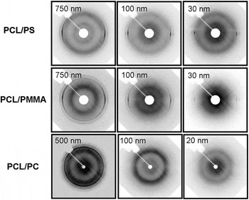
Polymethyl methacrylate (PMMA; Plexiglas VM, Arkema Inc., King of Prussia, PA) and polycarbonate (PC; Makrolon 2205, Bayer MaterialScience, Pittsburgh, PA) were utilized as amorphous substrates to confine PCL. Selection of these materials was solely based on increasing the interaction parameter between the amorphous substrate and PCL. The interaction parameter was determined for a 50/50 multilayered sample with referenced polymer solubility parameters, δ, and using the coextrusion processing temperature used to produce the films. PS represented a noninteracting substrate with PCL χPCL-PS = 0.168, PMMA represented an intermediate case with χPCL-PMMA = 0.017, while PC was miscible with χPCL-PC = 0Reference Liu, Bernal-Lara, Hiltner and Baer66, Reference Brandrup and Immergut69, Reference Karam and Solc70. All of these polymers provided confinement the PCL during coextrusion due to the T g of each material (T g,PS = 95 °C, T g,PMMA = 100 °C, T g,PC = 150 °C) being greater than that of the PCL crystallization temperature, T c,PCL = 25 °C. Since the PCL crystallized against a hard confining layer for all three systems, the confinement of PCL is therefore affected only by the polymer/polymer interactions during PCL crystallization. The PCL crystal orientation as a function of layer thickness was determined using WAXS for each of the three systems (Fig. 12).
ED WAXS patterns as a function of PCL layer thickness for the PS/PCL, polymethyl methacrylate (PMMA)/PCL, and polycarbonate (PC)/PCL nanolayered films.

From the ED WAXS images for the PMMA/PCL system, the morphology of PCL changes from spherulitic to oriented in-plane lamellae as a function of layer thickness indicated by the sharpening of the PCL (110) and (200) reflection arcs at the equator. The PCL structure evolution is consistent with the results from the PS/PCL system; however, comparing the ED WAXS images for the PS/PCL and PMMA/PCL systems at the same layer thickness reveals striking differences between the two systems. At 750- and 100-nm PCL layer thickness, the PMMA/PCL system exhibits broader equatorial PCL (110) and (200) arcs indicative of lower PCL crystal orientation compared to the PS/PCL system. At the thinnest 30-nm layers, both PMMA/PCL and PS/PCL exhibit sharp equatorial arcs consistent with highly oriented in-plane PCL lamellae irrespective of the confining substrate. The increased chemical interaction between PMMA/PCL relative to PS/PCL appears to retard the formation of in-plane PCL crystalline lamellae.
For the highly interacting PC/PCL system, at 500-nm PCL layer thickness, the ED WAXS images show an isotropic PCL (110) reflection indicating very little PCL crystal orientation.Reference Ponting, Keum, Freeman, Hiltner and Baer71 At 100-nm PCL layer thicknesses and below, the ED WAXS reveals the absence of any PCL crystalline reflections. Considering the miscibility behavior of PCL/PC blendsReference Di Lorenzo, Pietra, Errico, Righetti and Angiuli63 and the increased surface to volume ratio in multilayered structures, the resulting amorphous structure in the PC/PCL multilayered films indicated by WAXS resulted from the interdiffusion between PCL and PC layers. It is important to note that for the PC/PCL system, no PCL orientation was observed as a function of layer thickness. Both PS/PCL and PMMA/PCL systems possess some weak PCL crystal orientation even in thick micron-scale layers. The lack of any PCL orientation in the PC/PCL system suggests that some type of boundary, either sharp or diffuse, must exist in order induce the confined crystalline orientation in multilayered systems.
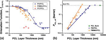
Similar to the previous work using PEO, the variations in PCL structure from different substrates have a large effect on the degree of orientation in addition to the oxygen permeability properties in these three systems containing PCL (Fig. 13). The differences in the PCL structure evolution, resulting from changing the interaction parameter of the substrate, were quantitatively described by calculating the degree of orientation using Herman’s orientation function and using the azimuthal intensity distributions of the PCL (110) reflection measured on the ED WAXS pattern. For the PS/PCL system, the confinement of PCL can be seen with micron-thick PCL layers. As the layer thickness is decreased, the PCL crystal orientation approaches in-plane at layer thicknesses below 100 nm. Changing the confining layer from PS to a more interacting PMMA shifted the observed PCL morphology change from isotropic to in-plane lamellae to thinner layers. For 200- to 1000-nm PCL layer thicknesses, the PMMA/PCL system possessed a lower degree of orientation compared to the PS/PCL system. At PCL layer thicknesses below 100 nm, the PCL lamellae orientation for the two systems converges with each system possessing nearly identical PCL lamellae orientation at the thinnest 30-nm PCL layers. The spatial confinement of the PCL polymer appears to take precedence over the interaction between PCL and the confining layer in the thinnest layers. Confirming the WAXS results, analysis of the f 110 for the PC/PCL films indicated a completely random PCL lamellae orientation regardless of the layer thickness.
(a) Orientation function f 110 versus nominal PCL layer thickness for the PS/PCL, PMMA/PCL, and PC/PCL systems. (b) Effective PCL oxygen permeability calculated from the series model versus nominal PCL layer thickness for the PS/PCL and PMMA/PCL systems. Adapted with permission from M. Ponting, Y. Lin, J. K. Keum, A. Hiltner, E. Baer: Effect of substrate on the isothermal crystallization kinetics of confined poly(ε-caprolactone) nanolayers. Macromolecules 43, 8619 (2010). Copyright 2010, American Chemical Society.

The effect of the confining substrate was also seen in the oxygen permeability properties. For the PMMA/PCL system, deviation in the effective PCL layer oxygen permeability from that of bulk occurred at thinner layers, around 700 nm in PMMA/PCL, compared to 4 μm for the PS/PCL system. Below 700 nm, there is a steady decrease in PCL effective permeability with decreasing layer thickness for the PMMA/PCL system; however, the values are much higher when comparing to the PS/PCL system at similar layer thicknesses. When the PCL layer thickness was reduced to 100 nm and below, the effective PCL permeability values converge for the two systems in the same manner as the PCL crystal orientation. At the thinnest 30-nm layers, the two systems possess nearly identical effective PCL permeability values. Finally for the PC/PCL system, oxygen barrier measurements were not carried out since there were no measurable levels of crystallinity as observed from the WAXS experiments.
The effect of quench temperature, T q, on the PCL crystal orientation was determined for the PMMA/PCL system and compared to the previously described PS/PCL system (Fig. 14). The technique utilized was identical to that used for the PS/PCL system due to the overlapping T g’s of PS and PMMA. For the PMMA/PCL system, the transition region for the in-plane to on-edge PCL lamellae orientation is shifted to lower temperatures and occurs over a broader temperature range, −20 to 10 °C, compared to −10 to 10 °C for the PS/PCL system. The increased interaction between the PMMA and PCL slows the formation of on-edge lamellae at lower temperatures while also broadening the temperature transition window for on-edge to in-plane transition. Increased polymer chain entanglements and a thicker PMMA/PCL layer interphase may be prohibiting the rapid PCL on-edge lamellae formation in rapidly quenched samples at low ambient temperatures.
ED WAXS patterns for PMMA/PCL nanolayered films with 40-nm PCL layer thickness quenched at various T q. Herman’s orientation function PCL f 110 as a function of quench temperature for both PS/PCL and PMMA/PCL systems indicating the different transition regions in PCL crystal orientation from in-plane to edge-on as T q is decreased.

The PMMA substrate also had a substantial impact on the crystallization kinetics of PCL under confinement. Isothermal crystallization kinetics of in-plane PCL lamellae at 40 °C was determined for the PMMA/PCL system and compared to the PS/PCL system. Crystallization data was plotted using the Avrami theory to determine the crystallization rate constant, k, and the Avrami exponent, n. The more interactive PMMA/PCL system showed almost an order-of-magnitude decrease in the crystallization rate constant in the thinnest 50-nm PCL layers compared to the PS/PCL system while the Avrami exponent maintained an integer value of 2.0 signifying that 2D growth was maintained and only the crystallization rate was affected with the increased PMMA/PCL layer interphase interactions. For the PS/PCL system, the Haudin model described the confinement of PCL against PS with decreasing layer thickness, d, only when N V was adjusted to obtain the best fit to the data. In contrast, for the PMMA/PCL system, the G 0 and N V values obtained for bulk PCL satisfactorily described the crystallization behavior of nanolayer confined PCL against PMMA. The constant N V values for the PMMA/PCL system could be explained by the very low levels of additives and stabilizers reported for commercial PMMA resins. A large decrease in N A for the PMMA/PCL system with decreasing PCL layer thickness was observed even though the N V values were constant, which would facilitate the formation of large in-plane PCL lamellae. In addition to polymer–polymer interactions, the confining amorphous substrate can also provide additional nuclei through diffusion. This will affect the crystallization kinetics as demonstrated for the case of PS/PCL and PMMA/PCL.
3. PCL: Effect of crystalline confining substrates
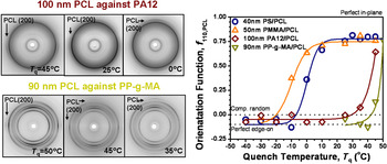
Two semicrystalline polymers, polyamide 12 (PA12; Grilamid LG20, EMS-Grivory, Sumter, SC) and polypropylene-graft-maleic anhydride with 0.2 wt% maleic anhydride (PP-g-MA; Polybond 3002, Chemtura Corporation, Middlebury, CT), were used as confining layers to confine PCL in nanolayered films to probe the effect of crystalline substrates on the confined crystallization mechanism. Unlike the PS/PCL and PMMA/PCL systems, both as extruded PA12/PCL and PP-g-MA/PCL nanolayered films with PCL layer thicknesses below 100 nm displayed mostly isotropic PCL lamellae orientation from WAXS (not shown). During nanolayer coextrusion, both systems were rapidly quenched to room temperature when the samples were collected. As previously described, the PCL lamellae orientation can be manipulated by changing the T q as long as the confining layer T g or T m is greater than the T m of PCL as is the case with PA12 and PP-g-MA because of their high melting points (T m,PA12 = 178 °C, T m,PP-g-MA = 161 °C). This same melt recrystallization technique was used with the PA12/PCL and PP-g-MA/PCL films to determine the temperature dependence of the PCL crystal orientation under confinement by a semicrystalline material.Reference Ponting, Keum, Freeman, Hiltner and Baer71 ED WAXS patterns were measured as a function of T q for both PA12/PCL and PP-g-MA/PCL systems and revealed dramatic differences when compared to the PCL systems containing amorphous confining layers (Fig. 15). To quantitatively describe the PCL lamellae orientation, Herman’s orientation function was calculated using the azimuthal intensity distributions of the PCL (110) reflection measured on the ED WAXS and plotted as a function of T q (Fig. 15). For comparison, the PS/PCL and PMMA/PCL systems were both added to the plot.
Top left: ED WAXS patterns for polyamide-12 (PA12)/PCL nanolayered films with 100-nm PCL layer thickness quenched at various T q. Bottom left: ED WAXS patterns for polypropylene-graft-maleic anhydride (PP-g-MA)/PCL nanolayered films with 90-nm PCL layer thickness quenched at various T q. Right: Herman’s orientation function PCL f 110 as a function of quench temperature for all crystalline and amorphous systems indicating the different transition regions in PCL crystal orientation from in-plane to edge-on as T q is decreased.

T q had a dramatic impact on the PCL lamellae orientation for the PA12/PCL and PP-g-MA/PCL nanolayered systems. At T q lower than 30 °C, both crystalline systems produced either an on-edge or an isotropic PCL lamellae orientation. At higher T q, above 45 °C, the PCL was successfully crystallized into in-plane lamellae for both crystalline systems. The confinement of PCL by crystalline polymer substrates significantly shifts the on-edge to in-plane lamellae transition to much higher temperatures, nearly 50 °C, as compared to the PS/PCL and PMMA/PCL systems. This suggests that the inclusion of a crystalline confining layer introduces additional thermodynamic or kinetic parameters to the confined crystalline layer behavior. It was speculated that transcrystallization at the crystalline confining layer interface may explain the affinity for PCL to crystallize on-edge at or below 40 °C. Chatterjee and coworkersReference Chatterjee and Price57–Reference Chatterjee and Price59 have studied the heterogeneous nucleation of crystalline polymers, including PCL, sandwiched against various millimeter-thick substrates in three-layer laminates. It was demonstrated that polymer substrates, including PP and polyamide polymers, can nucleate PCL at the substrate/polymer interface producing a transcrystalline or mixed transcrystalline/spherulitic crystal morphology in the PCL layer. By increasing the recrystallization temperature above an experimentally determined transcrystallization range, reported as 45–52 °C for PCL, the substrate surface was deactivated allowing for bulk heterogeneous spherulitic crystallization to occur in PCL. These results are shown for the first time to extend into the nanoscale with the PCL lamellae orientation behavior seen in the PA12/PCL and PP-g-MA/PCL nanolayered films. Additionally, high recrystallization temperatures are required to deactivate the surface of the confining crystalline substrate and allow for bulk heterogeneous nucleation of PCL in order to achieve in-plane PCL lamellae orientation by nanolayer confinement.
The selection of an appropriate confining material, based on thermal and chemical compatibility or physical structure (crystallinity), is paramount for achieving a high degree of confined polymer crystal orientation and also maximizing properties such as oxygen barrier. Substrate variables that can impact nanolayer-induced confined crystallization include but are not limited to: type of substrate (crystalline versus amorphous), interaction between amorphous substrate and confined polymer, confining polymer thermal properties, additives/stabilizers in the confining polymer, and recrystallization or quench temperatures. The above studies highlight not only the generality of the nanolayer-induced confined crystallization but also the unique ability to design and control this crystallization phenomenon in nanoscale architectures.
III. PART II: CONFINEMENT OF PP AND PVDF FREE RADICAL POLYMERS
Both PEO and PCL confined against various confining substrates exhibit an anisotropic in-plane crystal orientation in extruded nanolayered films. To further explore the generality of the confined crystallization mechanism, additional polymers that would display similar crystal morphologies under nanolayer confinement were sought. Previously, the structure of confined commodity polymers, such as PP and HDPE, was studied in multilayered films.Reference Jin, Rogunova, Hiltner, Baer, Nowacki, Galeski and Piorkowska72–Reference Bernal-Lara, Masirek, Hiltner, Baer, Piorkowska and Galeski74 The results revealed the formation of unique crystal morphologies and orientations when confined in nanolayers and will be summarized in this section for PP. Following the confinement work of PEO and PCL, the confined crystallization of a range of semicrystalline polymers has been studied, which include PET, poly(vinylidene fluoride) (PVDF), poly(oxymethylene) (POM), PLA, PA6, PA12, and poly(4-methyl-1-pentene) (4MP1). It was discovered that in-plane lamellae crystal orientation in extruded nanolayered films is in fact unique to PEO and PCL to our current knowledge. It is important to note that the quench temperature during the film take-off process was higher than the T c of PEO and PCL. For the additional polymers listed above, the films were quenched well below their T c resulting in the inability to control the confined crystal growth. An approach of melt recrystallization was successfully utilized to control the crystal orientation of both PEO and PCL lamellae as discussed previously. The results open an opportunity to produce oriented lamellae, on-edge or in-plane, in some of the other confined polymers listed above. Part II will discuss the confinement of free radical polymers, specifically PP and PVDF. Their crystallization behavior in extruded films is summarized in addition to the utilization of the melt recrystallization technique to control the crystal habit under hard confinement.
A. Section I: Crystallization of iPP and sPP in multilayered films
1. Crystallization of iPP in multilayered films
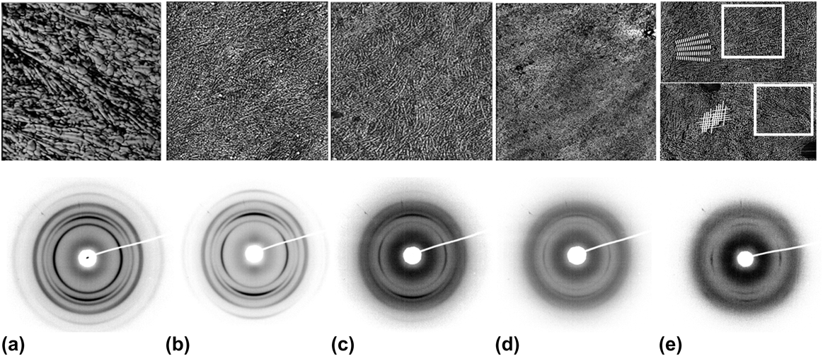
Crystallization of iPP (P4G2Z-073A, Hunstman Corporation, Freeport, TX) was studied in multilayered films against PS (Styron 685D, The Dow Chemical Company, Freeport, TX) with the nanolayers of iPP confined down to the size scale of the iPP lamellar thickness of 10–16 nm.Reference Mezghani, Campbell and Phillips75 The confined morphology of the exposed microlayer iPP surfaces from AFM are shown in Fig. 16. Typical bulk PP exhibits a crosshatched α-lamellar morphology. As the iPP layers were confined in multilayered films, the resulting morphology appeared as flattened spherulites or discoids. At 460- and 108-nm iPP layer thickness, the morphology consisted of on-edge lamellae with a dense crosshatched texture. Under confinement, the radial lamellae are oriented in the plane of the film; however, the lamellae texture appeared to be not as well organized compared to the iPP control [Figs. 16(b) and 16(c)]. Upon further reduction to 65-nm iPP layers, the morphology was comparable to that seen in thicker layers; however, the lamellae were noticeably thinner and shorter [Fig. 16(d)]. Under the highest degree of confinement, 10-nm iPP layers possessed a varied lamellae texture showing fragments of discoids, consisting of fan-like stacks of lamellae or bundles, which were randomly oriented in the plane of the layer, short lamellae fragments, and small areas of crosshatched lamellae [Fig. 16(e)].
2 × 2 μm AFM phase images showing lamellar morphology: (a) Bulk PP film; (b) a 460-nm PP layer; (c) a 108-nm PP layer; (d) a 65-nm PP layer; (e) a 10-nm PP layer. Corresponding two-dimensional (2D) transmission diffraction patterns of the PP control and films with 460-, 108-, 65-, and 10-nm PP layers in the transverse (T) direction. Adapted with permission from Y. Jin, M. Rogunova, A. Hiltner, E. Baer, R. Nowacki, A. Galeski, E. Piorkowska: Structure of polypropylene crystallized in confined nanolayers. J. Polym. Sci., Part B: Polym. Phys. 42, 3380 (2004). Copyright 2004, John Wiley and Sons.

It is interesting to note that the diameter of the discoids should increase significantly as the layers become thinner as the bulk primary nucleation density is unaffected and area nucleation density is decreased.Reference Jin, Rogunova, Hiltner, Baer, Nowacki, Galeski and Piorkowska72 However, little change in the discoid diameter is observed with decreasing the iPP layer thickness, suggesting that the confined discoids are nucleated at the iPP/PS interface, thus controlling the discoid size. A weak nucleating effect of the interface has been reported in literature for iPP and PS when iPP was crystallized in a bilayer sandwich.Reference Bartczak, Galeski and Krasnikova76 The confined iPP layers also possessed similar morphological features to spherulites crystallized in thin films that have a free surface, such as elevated central regions and lowered peripheral regions.Reference Nowacki, Kolasinska and Piorkowska77 Large depressions are also observed at the spherulitic boundaries. Volume contraction during iPP crystallizationReference Galeski and Piorkowska78 accounts for these morphological features and is observed in multilayer films under PS confinement because of the crystallization of the iPP discoids occurring above the T g of PS, T c,PP = 110 °C > T g,PS = 95 °C.
The 2D WAXS patterns of confined iPP layers with decreasing layer thicknesses in the transverse direction are shown in Fig. 16, along with the corresponding AFM images. Strong orientation of (040) crystal planes parallel to the layer interface, as indicated by the presence of meridional arcs, was observed in 460-nm layers. A slight orientation of the (110) planes was also seen, which was attributed to orientation from the extrusion process. As the layer thickness decreased to 65 nm, the presence of a meridional reflection for (110) plane demonstrated a weak trace of a new crystal texture with the crystal population having the chain axes parallel to the film plane. The new textural component was well resolved in 10-nm layers.
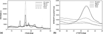
Analysis of the relative intensities of various crystal reflections revealed the changes in crystal structure of iPP in multilayered films [Fig. 17(a)]. As the layer thickness decreased, a shift of the (040) and (110) crystal reflections toward larger values was observed. This shift was more evident in 65- and 10-nm layers, which indicated that the spacing between (040) and (110) crystal planes decreased, resulting in tighter packing in the crystal unit cell in the directions perpendicular to the chain direction. The confinement also showed a strong impact on the registry along the chain axis, which worsened or was even lost as identified by the disappearance of the (−113) peak [Fig. 17(b)]. In addition to the disappearance of the (−113) peak, the absence of a long period in SAXS patterns confirmed poor crystallographic packing in the chain directions and defective crystal surfaces. Tighter chain packing perpendicular to the chain direction and poorer order along the chain directions were characteristic features of iPP crystals in 65- and 10-nm layers. However, AFM images of the 65- and 10-nm layers revealed distinguishable crystalline lamellae, along with numerous lamellar fragments or globular forms with a diameter of 12–16 nm. Similar features were previously observed in quenched polypropylene by Norton and Keller,Reference Norton and Keller79 which were indentified with the early stages of lamellae growth and branching.
(a) One-dimensional (1D) reflection WAXS 2θ scans of the PP control film and the layered films. (b) Transmission 1D WAXS 2θ scans of the (−113) reflection of the polypropylene α crystals. Adapted with permission from Y. Jin, M. Rogunova, A. Hiltner, E. Baer, R. Nowacki, A. Galeski, E. Piorkowska: Structure of polypropylene crystallized in confined nanolayers. J. Polym. Sci., Part B: Polym. Phys. 42, 3380 (2004). Copyright 2004, John Wiley and Sons.

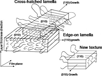
Based on morphological observations and x-ray analysis, it is clear that the 108- and 65-nm layers largely consisted of thin discoids while 10-nm layers consisted of fragments of discoids with the (040) planes lying flat on the interface. Prior work on the crystallization of thin films of iPP on mica showed that the dendritic discoids of iPP were poorly filled with crystals.Reference Lotz, Wittmann and Lovinger80 Similarly, it is suggested that the internal structure of iPP in 65- and 10-nm layers is also difficult to fill with branching lamellae. Additionally, growth of crystals with the (010) planes lying flat on the interface is limited to the thickness of the layer, which restricts secondary nucleation of the crosshatched lamellae (Fig. 18). WAXS from 65- and 10-nm layers also revealed a small fraction of (040) planes perpendicular to the interface with the (110) planes parallel to the interface, suggesting changes in the crystal growth plane from the usual (110) to the more rare (010) plane (Fig. 18). This population of crystals suggests the possibility of a different nucleation mechanism (at the interface) or formation of the crystals in a later stage of cooling.
Schematic showing an edge-on radial or mother lamella that nucleated at the interface with the (010) planes flat-on. The crosshatched lamella formed by secondary nucleation on the (010) plane. The width of the radial lamella and the amount of crosshatched overgrowth are limited by the thickness of the PP layer. In the 65- and 10-nm layers, a second crystal population nucleates at the interface with the (110) planes flat-on. Reprinted with permission from Y. Jin, M. Rogunova, A. Hiltner, E. Baer, R. Nowacki, A. Galeski, E. Piorkowska: Structure of polypropylene crystallized in confined nanolayers. J. Polym. Sci., Part B: Polym. Phys. 42, 3380 (2004). Copyright 2004, John Wiley and Sons.

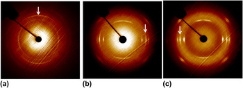
Multilayered films of PS/iPP showed formation of new structures as the layer thickness approached the iPP lamellar thickness. However, as the coextruded films were quenched to room temperature during the take-off process, specific control over the crystallization of iPP was not achieved. As previously established for both PEO and PCL, an approach of melt recrystallization is effective at controlling the confined polymer crystal orientation.Reference Wang, Keum, Hiltner and Baer46 The PS/iPP system does not, however, possess an appropriate temperature window for melt recrystallization, as T m,PP > T g,PS. Therefore, the PS was substituted for a higher T g material. A set of multilayered films constituting alternating layers of iPP (ZN5D98, The Dow Chemical Company, Freeport, TX) and PC (Apec 1803, Bayer MaterialScience, Pittsburgh, PA) was investigated. The specific PC used was a high T g grade, T g,PC = 183 °C, which allowed for melt recrystallization of the iPP to be carried out under hard confinement, which was not possible in PS/iPP system. Examples of iPP crystallized at 140 °C for 72 h, which was well above the T c of iPP of 110 °C, are shown in Fig. 19. When iPP was crystallized, the orientation of (040) crystallographic planes changed from parallel to the layer interface to perpendicular to the layer interface. In addition, the new textural components observed in the PS/iPP and PC/iPP extruded films were also maintained in the isothermally crystallized layers. Thus, it is suggested that the lamellae assumed in-plane orientation with the (040) planes lying perpendicular to the layer interface.
2D transmission diffraction patterns of the multilayered PC/isotactic polypropylene (iPP) films: (a) with 70/30 composition, 120-nm iPP layers; (b) with 70/30 composition, 120-nm syndiotactic polypropylene (sPP) layers crystallized isothermally at 140 °C for 72 h; (c) with 80/20 composition, 80-nm iPP layers crystallized isothermally at 140 °C for 72 h. The patterns were obtained in the transverse direction. The arrows mark the (040) reflection.

2. Crystallization of sPP in multilayered films:
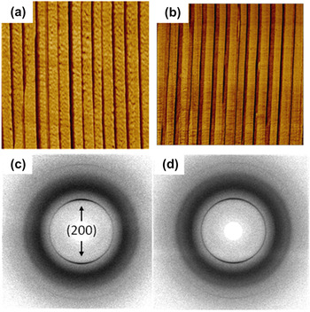
A polyolefinic candidate, sPP (MN 75000, MW 174000, 93% sydiotacticity, Sigma Aldrich, St. Louis, MO), is investigated to broaden the spectrum of confined polymers.Reference Langhe, Hiltner and Baer81 Multilayered films with sPP confined against PC (Calibre 200-15, The Dow Chemical Company, Freeport, TX) were produced with the sPP layer thicknesses reduced down to 30 nm. AFM images of the cross sections of PC/sPP films showed continuous layers and did not possess any sPP lamellar morphology under the confinement of PC (Fig. 20). It is suggested that the absence of any morphological features in sPP layers may have resulted due to its low crystallinity. It is interesting to note that the initial bulk crystallinity of sPP layers (14%) was substantially lower than the initial bulk crystallinities of PEO (75%) and PCL (40%). Additionally, the sPP crystallinity was further reduced in the extruded films. X-ray diffractograms for extruded PC/sPP films were collected in the ED [Fig. 20(c)]. Broad arcs at 2θ = 12.8° were assigned to the (200) reflection based on the cell II structure of sPP.Reference Harasawa, Uehara, Yamanobe and Terano82 Additional reflections at 25.2° for the (002) crystal plane were also observed. The presence of broad (200) reflections at the meridian indicated some c-axis orientation parallel to sPP layers, implying weak on-edge orientation of sPP lamellae perpendicular to the layers. The sPP crystal reflections were not significantly affected by decreasing in the layer thickness. In addition to the crystalline reflections of sPP, the WAXS patterns also contained an amorphous halo for PC at 2θ = 17°. The weak sPP lamellar orientation and low crystallinity were attributed to the rapid quenching of the film during the film take-off process.
AFM phase images of extruded PC/sPP films with (a) 80/20 composition, 80-nm nominal sPP layer thickness and (b) 70/30 composition, 120-nm nominal sPP layer thickness. The measured layer thicknesses were 85 ± 13 and 122 ± 15, respectively. Corresponding ED WAXS patterns of 80- and 120-nm sPP layer thickness. Reprinted from Melt crystallization of syndiotactic polypropylene in nanolayer confinement impacting structure, doi: 10.1016/j.polymer.2011.10.018, D. S. Langhe, A. Hiltner, E. Baer, Copyright (2011), with permission from Elsevier.

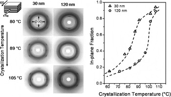
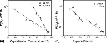
An approach of melt recrystallizationReference Wang, Keum, Hiltner and Baer46 of sPP under the hard confinement of PC was applied to control the orientation habit of sPP lamellae. The sPP layers were melted under the hard confinement of PC at 145 °C, which was below the PC T g of 150 °C. The layers were then quenched to the desired crystallization temperature. The crystal orientation of the sPP showed significant changes as a function of crystallization temperature. Two examples of sPP layer confinement, 30- and 120-nm layer thicknesses, are shown (Fig. 21).
2D WAXS patterns (ED direction) showing sPP crystal orientation in PC/sPP films with various sPP layer thicknesses. The sPP layers were melted at 145 °C for 5 min and quenched to different temperatures (T c). The results from PC/sPP films with 30- and 120-nm sPP layer thicknesses are shown. The T c is as labeled in the figure. In-plane crystal fractions obtained from 2D WAXS patterns of isothermally crystallized sPP layers. Results from PC/sPP films with 30- and 120-nm sPP layer thicknesses are shown. Crystallization temperature range studied from 60 to 105 °C. Dotted lines are shown as guides. Reprinted from Melt crystallization of syndiotactic polypropylene in nanolayer confinement impacting structure, doi: 10.1016/j.polymer.2011.10.018, D. S. Langhe, A. Hiltner, E. Baer, Copyright (2011), with permission from Elsevier.

Both 30- and 120-nm layers showed the presence of on-edge lamellae at low crystallization temperatures. As the crystallization temperature increased, stronger equatorial arcs confirmed the formation of the in-plane crystals with chains lying perpendicular to the layer plane. When the crystallization temperature was sufficiently higher (>90 °C for 30-nm layers and >100 °C for 120-nm layers), most of the sPP was crystallized in-plane (Fig. 21). Thus, the general trend of WAXS patterns indicated a marked increase in the sPP in-plane crystal orientation with increasing recrystallization temperature (Fig. 21). The relative in-plane crystal fractions were strongly dependent on the initial layer thickness. On-edge to in-plane transition temperatures were shifted to lower temperatures as the layer thickness changed from 120 to 30 nm. Previously, it has been observed that as the layer thickness was reduced, the growth rates were significantly reduced.Reference Ponting, Lin, Keum, Hiltner and Baer34, Reference Wang, Keum, Hiltner and Baer39 It is speculated that the growth rates of the two sPP crystal orientations under layer confinement and the area nucleation density are both important parameters impacting the relative crystal orientation fractions. As seen in Fig. 21(a), all the samples showed the presence of on-edge lamellae irrespective of the crystallization temperature used. The results were attributed to either atactic or other stereoblocks present in sPP, which showed the presence of axilitic morphology.Reference Lovinger, Lotz, Davis and Padden83 As stated in earlier sections, substrate-assisted nucleation was proposed for the formation of on-edge lamellae and bulk heterogeneous nucleation for in-plane crystals.Reference Wang, Keum, Hiltner and Baer46 Additional possibilities at lower temperature also include fine-scale microfaceting in the crystallization of the thin films with screw dislocations during rapid growths.Reference Lovinger, Lotz, Davis and Schumacher84
As it was possible to control the relative fractions of the orientated crystals in PC/sPP films without significant formation of random crystals, it facilitated oxygen transport measurements and correlation with the observed morphology. A gradual reduction in the oxygen permeability of sPP layers was observed as the crystallization temperature increased from 85 to 105 °C [Fig. 22(a)]. It is intuitive that the on-edge lamellae of the confined sPP recrystallized at lower temperatures offered minimal hindrance for the oxygen transport, resulting in an increased gas flux. The increased fraction of in-plane crystals resulted in improved oxygen barrier properties as previously seen with PEO and PCL. In-plane crystals acted as impermeable platelets and increased the tortuosity for gas diffusion. Further correlation between the oxygen permeability and the in-plane crystal fraction was also obtained for a given temperature range. The empirical correlation can be given as Exp[P(O2)] ∝ (F In−plane)−1, where F in-plane is the in-plane fraction of sPP lamellae [Fig. 22(b)]. It is assumed that the size of the in-plane crystals and crystallinity were not affected significantly within the experimental temperature range under consideration. Successful control over the crystallization habit of sPP under nanolayer confinement was achieved and used to manipulate the gas transport properties of the films over at least one order of magnitude.
(a) Effective permeability of the sPP layers as a function of crystallization temperature. The dotted lines are shown as guides. (b) Correlation between sPP and the in-plane fraction calculated from WAXS patterns. The dotted lines are shown as a guide. Reprinted from Melt crystallization of syndiotactic polypropylene in nanolayer confinement impacting structure, doi: 10.1016/j.polymer.2011.10.018, D. S. Langhe, A. Hiltner, E. Baer, Copyright (2011), with permission from Elsevier.

B. Section II: Confined crystallization of PVDF and PVDF–TFE
Confined crystallization studies using PVDF are useful due to its wide range of commercial applications including sensors, energy storage, transducers, membranes, chemical barriers, and fluid transportation.Reference Lovinger85–Reference Choi, Jo, Lee and Kim88 By changing the crystal orientation in nanolayers, the bulk film properties can be influenced and in many cases enhanced as in the previously discussed case with PEO and PCL. PVDF is a high crystallinity polymer, with Xc = 50 wt%, which crystallizes into many different crystal forms depending on the processing conditions.Reference Mackey, Flandin, Hiltner and Baer85Reference Mackey, Flandin, Hiltner and Baer,89 Homopolymer PVDF (Solef 6010, Solvay Solexis, Thorofare, NJ), which primarily forms α-phase crystals during crystallization from the melt,Reference Nalwa89 was confined against both PC (Calibre 200-6, The Dow Chemical Company, Freeport, TX) and polysulfone (PSF; Udel P-3703, Solvay Solexis, Thorofare, NJ).Reference Mackey, Flandin, Hiltner and Baer90 PC and PSF were chosen based on their high T g, T g,PC = 150 °C, T g,PSF = 186 °C, compared to the crystallization temperature of PVDF, T c,PVDF = 131 °C. During coextrusion, both confining layers solidified before the crystallization temperature of PVDF allowing for hard confinement. Additionally, melt recrystallization experiments can be carried out of the PSF/PVDF system because on the T g of PSF being higher than the T m of PVDF, T m,PVDF = 172 °C.
Many commercially available PVDF copolymers are also of interest for confined crystallization studies. One copolymer, in particular, poly(vinylidene fluoride-co-tetrafluoroethylene) (PVDF–TFE) (Neoflon VP-50, Daikin Industries, Osaka, Japan) with 20 mol% TFE comonomer, was chosen for confined crystallization against PC (Makrolon 2207, Bayer MaterialScience) because of its ability to produce a different crystal phase compared to homopolymer PVDF.Reference Mackey, Flandin, Hiltner and Baer90 Crystallization of this PVDF–TFE copolymer from the melt results in the formation of primarily β-phase crystals.Reference Nalwa89 This copolymer contains around a 32 wt% crystallinity, a T m of 125 °C and a T c of 110 °C. PC as a confining layer to PVDF–TFE would provide hard confinement during crystallization and allows for a large temperature window for melt recrystallization. For all three systems, nanolayered films were produced with PVDF and PVDF–TFE layer thicknesses ranging from 1 μm down to 30 nm. The PVDF and PVDF–TFE crystal orientation in extruded nanolayer films was investigated using WAXS.
For the extruded PC/PVDF and PSF/PVDF films with thick PVDF layers around 1 μm, both PC/PVDF and PSF/PVDF systems did not exhibit any preferential PVDF crystal orientation (not shown). As the PVDF layer thickness was reduced to 225 nm for both systems, the PVDF was oriented on-edge indicated by the appearance of broad α-PVDF (100) reflection arcs at the meridian (Fig. 23). At 30-nm PVDF layer thickness, the apparent on-edge PVDF crystal orientation was disrupted as indicated by the broadening of the α-PVDF (100) and (110) reflection arcs (not shown). The spatial limitations under 30-nm confinement disrupted the formation of on-edge α-PVDF lamellae producing a more disordered structure. For the PC/PVDF–TFE system, all layer thicknesses investigated showed only an isotropic β-PVDF–TFE (110) and (200) single reflection ring indicating that the β-PVDF–TFE crystal orientation was always isotropic (Fig. 23). These systems highlight that the fast quenching during nanolayer film collection does not always allow for ordered crystal growth of polymers with higher T c under confinement.
ED WAXS images of the PC/poly(vinylidene fluoride) (PVDF), polysulfone (PSF)/PVDF, and PC/PVDF–tetrafluoroethylene (TFE) nanolayered films with 225-nm PVDF and PVDF–TFE layer thicknesses. Adapted with permission from M. Mackey, L. Flandin, A. Hiltner, E. Baer: Confined crystallization of PVDF and PVDF-TFE copolymer in nanolayered films. J. Poly. Sci. Part B: Poly. Phy. doi: 10.1002/polb.22375. Copyright 2011, John Wiley and Sons.

Confinement of PVDF and PVDF–TFE in extruded nanolayered films did not produce the strong in-plane lamellae orientations seen in PEO and PCL. To improve the orientation, a melt recrystallization approach, similar to that used with PEO and PCL, was used to change to the confined crystallization habit in the PSF/PVDF and PC/PVDF–TFE systems.Reference Wang, Keum, Hiltner and Baer46 The PVDF or PVDF–TFE layers were first melted at a temperature above their respective T m but below the T g of the confining polymer. Molten PVDF and PVDF–TFE layers were subsequently recrystallized at various temperatures, T x, and times to change the confined crystal orientation. Crystallization times were determined based on DSC experiments, where the sample was held isothermally for a specific time and then slowly cooled at 10 °C/min to detect any crystallization during cooling. If the polymer is sufficiently crystallized, no exothermic peak was detected during the cooling cycle. The PSF/PVDF system was successfully recrystallized at 135 °C for 0.5 h, 145 °C for 5 h, and 170 °C for 96 h at all PVDF layer thicknesses. The PC/PVDF–TFE system was successfully crystallized at 110 °C for 0.4 h, 115 °C for 1 h, and 120 °C for 4 h at all PVDF–TFE layer thicknesses. WAXS was utilized to study the crystal orientation of each recrystallized system.
The PSF/PVDF system exhibited a dramatic change in both crystal orientation and PVDF crystal phase with melt recrystallization [Fig. 24(a)]. At T x = 135 °C and T x = 145 °C, in-plane α-PVDF crystals were successfully produced in very thin 30-nm layers indicated by the appearance of α-PVDF (100) and (110) arc reflections at the equator. In PVDF layers of 80 nm and above, the α-PVDF crystallized on-edge under confinement. For higher T x = 170 °C, γ-phase PVDF crystals formed instead of the more common α-phase.Reference Lovinger and Keith91 In-plane γ-PVDF crystals were also produced at T x = 170 °C for all layer thicknesses investigated. For the PC/PVDF–TFE system, recrystallization resulted in the formation of in-plane β-PVDF–TFE crystals in very thin 30-nm layers for all T x investigated as evidenced by the β(110) and (200) reflection arcs at the equator [Fig. 24(b)]. The degree of in-plane lamellae orientation was improved with increasing T x in thin layers; however, the β-PVDF–TFE (110) and (200) reflection arcs are still fairly broad in the WAXS. This suggested that the chain axis could potentially be tilted with respect to the lamellae fold surface normal direction. In thicker PVDF–TFE layers above 80 nm, recrystallization at T x = 115 °C and T x = 110 °C resulted in isotropic β-PVDF–TFE crystal orientation. It is important to note that the on-edge β-PVDF–TFE crystal orientation was not obtained for this system even when using very low quench temperatures. The melt recrystallization protocol for PEO and PCL was successfully used to manipulate the crystal orientation of PVDF and its copolymers. In addition to changing the crystal orientation, recrystallization can also result in crystal phase changes such as the case with PVDF under confinement. AFM was also used to track the morphology change of these recrystallized PVDF systems.
(a) ED WAXS and AFM images of the PSF/PVDF nanolayered films with 225- and 28-nm PVDF thicknesses at two recrystallization temperatures, T x = 135 °C, top row, and T x = 170 °C, bottom row. Adapted with permission from M. Mackey, L. Flandin, A. Hiltner, E. Baer: Confined crystallization of PVDF and PVDF-TFE copolymer in nanolayered films. J. Poly. Sci. Part B: Poly. Phy. doi: 10.1002/polb.22375. Copyright 2011, John Wiley and Sons. (b) ED WAXS and AFM images of the PC/PVDF–TFE nanolayered films with 225- and 28-nm PVDF–TFE thicknesses at two recrystallization temperatures, T x = 110 °C, top row and T x = 120 °C, bottom row. Adapted with permission from M. Mackey, L. Flandin, A. Hiltner, E. Baer: Confined crystallization of PVDF and PVDF–TFE copolymer in nanolayered films. J. Poly. Sci. Part B: Poly. Phy. doi: 10.1002/polb.22375. Copyright 2011, John Wiley and Sons.

AFM confirmed that the layered structure in the PSF/PVDF and PC/PVDF-TFE systems remained intact following the melt recrystallization process [Fig. 24(a) and 24 (b)]. In the PSF/PVDF system, the AFM showed a stacked granular morphology in 225-nm α-PVDF layers at T x = 135 °C. A granular structure, elongated in the layer plane, was seen in the 225-nm γ-PVDF layers at T x = 170 °C, which is consistent with the in-plane orientation determined from WAXS. The observed morphology in the thin 28-nm layers for both the α-PVDF at T x = 135 °C and γ-PVDF at T x = 170 °C appeared as single in-plane lamellae. Lamellae stacking and crystal boundaries in very thin layers were difficult to distinguish in this system compared to PEO and PCL. For the PC/PVDF–TFE system, the AFM images clearly show the appearance of stacked in-plane β-PVDF–TFE lamellae crystals in the 225 nm layers at T x = 120 °C. In 28-nm β-PVDF–TFE layers, all the layers appeared as single in-plane lamellae also consistent with WAXS.
The crystal habit, crystal phase, and degree of orientation were affected by the recrystallization temperature and layer thickness for the PSF/PVDF and the PC/PVDF–TFE systems. Oxygen permeability was an effective probe of crystal orientation for PEO, PCL, and sPP under confinement and was successfully used to study the effect of recrystallization temperature for the PSF/PVDF and PC/PVDF–TFE systems. The effective PVDF and PVDF–TFE permeability was calculated using the series model as a function of layer thickness for the extruded and recrystallized films (Fig. 25). The extruded PSF/PVDF and PC/PVDF–TFE films possessed effective permeability values that matched the bulk values for all layer thicknesses. The confined structure in the extruded films, either isotropic or on-edge, did not yield any effect on the oxygen barrier properties of the overall film. The recrystallized samples showed considerably different behavior. For the PSF/PVDF system, the effective permeability decreased by a factor of 30 with decreasing layer thickness. In very thin layers, recrystallization resulted in the formation of in-plane α or γ-PVDF crystals, which significantly improved the gas barrier properties. Using the Cussler model,Reference Cussler, Hughes, Ward and Aris42 the aspect ratio of the in-plane PVDF crystals was estimated to be as high as 100 for the thinnest PVDF layers. In contrast, the recrystallization temperature did not significantly affect the barrier properties of the PSF/PVDF system with decreasing layer thickness. The effect of recrystallization temperature on oxygen barrier properties was much more evident in the PC/PVDF–TFE system. Increasing T x yielded much lower effective oxygen permeability values for the PC/PVDF–TFE system. At T x = 120 °C, the thinnest layers possessed effective permeability values 100× lower than the bulk control. Higher T x created a much more defined and highly oriented in-plane β-PVDF–TFE lamellae structure as shown in the WAXS and AFM. The aspect ratio, calculated using the Cussler model, for the PC/PVDF–TFE system showed that higher T x resulted in much larger aspect ratios, as large as 80 for T x = 120 °C compared to around 20 for T x = 110 °C. The strong temperature dependence of the PVDF–TFE material is likely related to the fact that copolymers do not crystallize as easily as homopolymers.Reference Mandelkern92
Effective oxygen permeability of (a) PVDF and (b) PVDF–TFE as a function of layer thickness and recrystallization temperature. Adapted with permission from M. Mackey, L. Flandin, A. Hiltner, E. Baer: Confined crystallization of PVDF and PVDF–TFE copolymer in nanolayered films. J. Poly. Sci. Part B: Poly. Phy. doi: 10.1002/polb.22375. Copyright 2011, John Wiley and Sons.

The utilization of melt recrystallization is a critical feature when studying the confined crystallization of semicrystalline polymers under confinement using nanolayer coextrusion. This allows for specific control over the confined crystal orientation in addition to tailoring the final film properties. Using this protocol, the crystal orientation of PVDF and PVDF–TFE was controlled under confinement. For these systems, increasing the recrystallization temperature and decreasing layer thickness facilitated the formation of in-plane lamellae under confinement. The structure evolution in these systems can be compared to the previously described behavior in PEO, PCL, and iPP. For confined PVDF, extruded films possessed an on-edge discoid structure similar to the PS/iPP system described previously. Recrystallization at high temperatures deactivated the surface nucleation and allowed high aspect ratio in-plane crystals to form in thin layers because of a reduction in area nucleation density.Reference Wang, Keum, Hiltner and Baer46 Recrystallization of PVDF at 170 °C under confinement resulted in the formation of in-plane γ-phase lamellae. Extruded PVDF–TFE confined layers possessed an isotropic granular structure. In-plane β-PVDF–TFE crystals were observed with decreasing layer thickness and increasing recrystallization temperature. However, PVDF–TFE did not form on-edge β-crystals through recrystallization at lower temperatures, which implied that surface nucleation did not occur. Like PEO, PCL, and sPP, the in-plane PVDF and PVDF–TFE lamellae orientation showed a dramatic effect on the gas barrier properties. The recrystallization temperature can dramatically affect the crystal orientation and the degree of orientation while also impacting other polymer properties such as crystal phase.
IV. CONCLUDING REMARKS
It has demonstrated that confined crystallization induced from nanolayer confinement is an effective approach to manipulate the lamellae morphologies of crystalline polymers, which can dramatically affect bulk film properties including gas barrier. The unique layer thickness and temperature-dependent morphologies in a wide variety of polymers allow for potential commercial scale up using common film fabrication techniques. Confined structures produced using nanolayer coextrusion have many advantages over other techniques, including flexibility in polymer selection, continuous melt process using no solvents, and true 1D almost defect-free confinement. Common characterization techniques including AFM, gas transport, and x-ray scattering are effective tools to probe the confined polymer morphology under nanolayer confinement. We have also demonstrated the effect of different parameters that impact the crystal orientation at the lamellar scale, which include but are not limited to: type of confining substrate (crystalline versus amorphous), interaction between amorphous substrate and confined polymer, polymer thermal properties, additives/stabilizers in the confining polymer, and recrystallization or quench conditions. The knowledge and basic understanding obtained from studying confined crystallization under nanolayer confinement could also impact the design of future smart materials using other fabrication techniques.
The ability to produce these polymer structures using melt processing opens up the door to potential commercial applications. Packaging films are immediately attractive due to the enhancement in barrier properties from the confined lamellae structure. Steps to commercialization have already been realized in recent results where nanolayered PEO and PCL were successfully incorporated into a biaxially oriented PP structure.Reference Lin, Hiltner and Baer93, Reference Lin, Hiltner and Baer94 The resulting films possessed enhanced barrier properties while maintaining other important packaging properties such as optical clarity and mechanical toughness.
In addition to the reviewed polymers and techniques, other approaches and materials have been used to access the confinement using nanolayer coextrusion. Ultra-small-angle x-ray scattering has been used to characterize the lamellae structure of PET cold crystallized from the glass under nanolayer confinement.Reference Balta-Calleja, Ania, Puente-Orench, Baer, Hiltner, Bernal and Funari95–Reference Flores, Arribas, Fauth, Khariwala, Hiltner, Baer, Balta-Calleja and Ania97 An increase in microhardness and a change in micromechanical deformation behavior are observed in confined cold crystallized PET as the layer thickness is decreased.Reference Adhikari, Seydewitz, Loschner, Michler, Hiltner and Baer98, Reference Orench, Ania, Baer, Hiltner, Bernal and Balta-Calleja99 In another approach, dynamic mechanical analysis was used to study the chain mobility of PEO in PS/PEO and EAA/PEO nanolayered films.Reference Lai, Ayyer, Hiltner and Baer100 Viscoelastic models were used to accurately describe the dynamic behavior of PEO in these confined systems. Additionally, the nanolayer confined PEO was also found to increase the tensile modulus of the bulk film when measured at low temperatures. Finally, a styrene–ethylene/propylene–styrene triblock copolymer has been confined against PS and produced unique block copolymer phase morphologies and mechanical properties under nanolayer confinement.Reference Burt, Keum, Hiltner, Baer and Korley101 These studies highlight the vast areas of potential research on confined systems using nanolayer coextrusion.
Although we have addressed the confinement of crystallizable polymers in nanolayers, future studies on confinement of amorphous, block copolymers and engineering polymers are also of high interest. The desire moving forward is to utilize the confined crystallization technology beyond barrier properties to develop nanolayered structured materials with enhanced optical, mechanical, and electrical properties.
ACKNOWLEDGMENTS
This research was generously supported by the National Science Foundation through the Center for Layered Polymeric Systems (CLiPS) Science and Technology Center Grant DMR-0423914 and the Office of Naval Research Grant N00014-10-1-0349.