

INTRODUCTION
The celebrated Roman site of Richborough is located in east Kent, and occupies part of what was once a small island or peninsula on the south side of the Wantsum channel, the now silted arm of the sea, which formerly separated the Isle of Thanet from the mainland of Kent. The site has a long and complex known history, much of which derives from the results of the major excavations within the walls of the Saxon Shore fort conducted between 1922 and 1938 by J.P. Bushe-Fox. These excavations were published in an important and influential series of volumes produced by the Society of Antiquaries of London.Footnote 1
The sequence of occupation established by these excavations is well known. The earliest Roman features are a pair of long, parallel defensive ditches yielding material of Claudian date. Since these ditches were discovered, Richborough has been identified, though not without controversy, as the landing place of the successful Claudian invasion of a.d. 43. The Claudian phase was followed by a period during which the site was covered with streets and timber buildings, including a number of granaries. The remains of this phase (c. a.d. 43–85) are generally interpreted as those of a military supply base, but might equally represent the beginnings of civilian port development, as any such development would have required store buildings. Certainly in the pre-Flavian period, granaries were replaced with buildings of a more civilian and commercial appearance, and a possible mansio was built in the north-east corner of the excavated area.
Conventionally dated to c. a.d. 85, a great quadrifons triumphal arch was built at the site. Faced in Italian Carrara marble, this was probably the most imposing monumental structure built in Roman Britain, and it served as a symbolic entrance to the province. The construction of this monument coincided with the relaying of roads and the replacement of buildings, including commercial premises such as those in a metal-working area and a supposed lamp shop. Throughout the early second century stone-founded shop buildings appeared, and the town seems to have grown and flourished. As Bushe-Fox put it ‘from the second half of the first century to the second half of the third … a town existed which served the purpose of an adjunct to the port.’Footnote 2 The town appears to have contracted in the third century, though the mansio continued in use.
In the later third century, military use was reasserted when the quadrifons arch was fortified with ditches that sliced through urban buildings, although avoiding the mansio, which was retained. In the very late third century, the quadrifrons was demolished and the Saxon Shore fort was built, replacing some six insulae of the town and requiring the demolition of the mansio. Footnote 3 The fort continued in use into the fifth century, and is recorded as the entry point for the troops brought by Lupicinus in 360 and Theodosius in 368.Footnote 4
RECENT WORK
Recently, an extensive programme of geophysical survey has demonstrated the extent of the port town, which covered at least 21 ha,Footnote 5 though very little of this has ever been examined by excavation. When the railway to the east of the fort was built in 1846, part of a flint and tile-built ‘house’ with an apsidal room was destroyed,Footnote 6 and several pits were encountered. Some 350 m south of the fort, work on a (now obliterated) light-rail line in 1926 revealed two Romano-Celtic temples.Footnote 7 Between the temples and the fort were a cemetery, ovens and further stone buildings, elements of which occupy the site of the modern car park. Some 400 m south-west of the Saxon Shore fort, on the highest point of Richborough island, the amphitheatre was partially excavated by William Rolfe in 1849.Footnote 8 Geophysical survey on the amphitheatre has led to the publication of a reconsideration of this structure.Footnote 9
In tandem with the geophysical work, a programme of excavation and coring has been undertaken on the eastern side of the site under the direction of Tony Wilmott, to sample areas where geophysics is impracticable and to examine the dynamic processes of erosion and silting on the former waterfront. In 2001, two areas were excavated, including a partial re-examination of the temples excavated by Bushe-Fox, and in 2008 a series of trenches was excavated along and between blocks of the collapsed east wall of the fort.
Work on the publication of this new material continues,Footnote 10 but the clearance and examination of the collapsed east wall of the Saxon Shore fort has led to conclusions that fundamentally alter our understanding of the morphology of the fort, and it is these conclusions that are examined in this paper.
THE SAXON SHORE FORT PLAN: RECEIVED VIEW
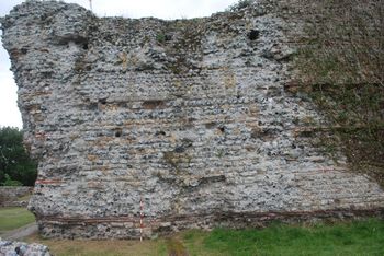
The ruins of the Saxon Shore fort at Richborough are imposing. The entire west wall, most of the north wall and a large portion of the south wall survive. The surviving wall height is up to 7 m, with the north wall being particularly well preserved. The walls are some 3.3 m wide at the base. The north-west and south-west corners feature circular angle towers. In the west wall a single-portal gate is located off-centre to the north (84.37 m north of the south angle tower and 48.7 m south of the north angle tower), and equidistant between this gate and the corner towers are rectangular interval towers (south of the gate the tower is 39.37 m from the gate and the corner tower; north of the gate the distance is 21.87 m). The gate, corner towers and angle towers survive as foundations. The angle towers do not appear to have been bonded with the curtain wall,Footnote 11 but the interval towers certainly were, and, where the towers have been robbed to foundation level, vertical scarring appears on the face of the curtain wall where the side walls were bonded in. On the north wall a postern gate contained within a square tower, which survives to almost full height, allows access to the fort interior through a dog-leg approach. This is situated 71.25 m from the north-west angle tower. Between the angle tower and the postern gate is a rectangular interval tower, but this is not equidistant between the two, lying 37.48 m east of the angle tower and 27.5 m west of the postern. This interval tower is mirrored by a counterpart on the south wall. Both interval towers are robbed to foundation level, and both show scarring on the curtain wall where the bonded side walls have been removed.
The surviving standing parts of the fort stand on a plateau, on the eastern side of which is an eroded scarp. The plateau is approximately level with the 10 m contour; the base of the scarp is some 5 m below. Erosion of the scarp has removed the entire east wall of the fort, the north-east corner and about 50 per cent of the south wall. The eastern wall and the north-east corner have collapsed, and elements of collapsed wall lie where they fell off the north-east corner and down-slope to the east.
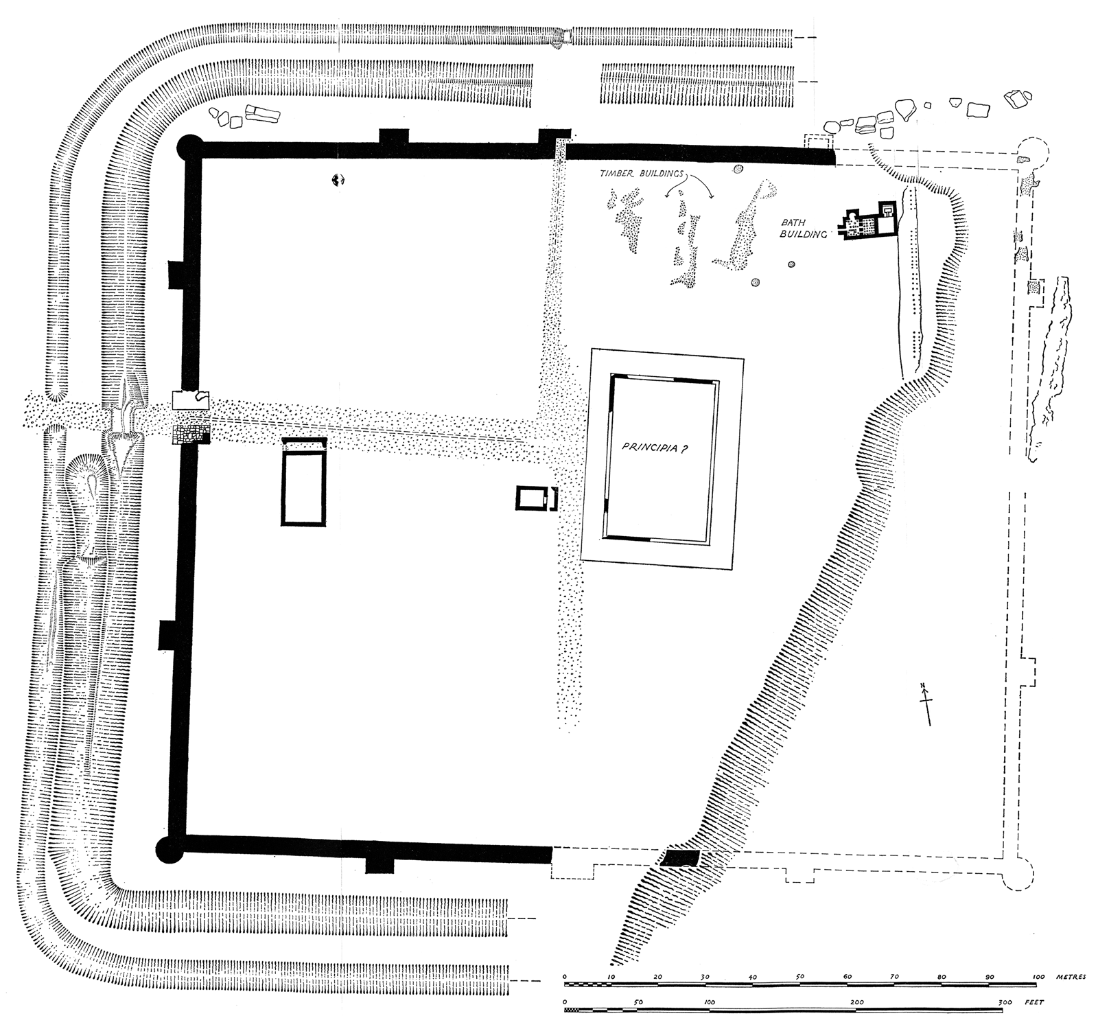
The generally accepted plan of the Saxon Shore fort is that published by Barry Cunliffe in his final (1968) report on the Bushe-Fox work (fig. 1).Footnote 12 The plan shows the surviving portions of the fort in solid black, while conjectured walls are mostly shown in a single outline of dashed lines, although the conjectured interval tower at the eastern end of the surviving north wall is shown differently – as a double-dashed outline (see below). Although unlabelled in this version of the plan, north of the north wall on the east side are several block outlines, representing elements of collapsed wall. The collapsed wall on the east side is represented by a somewhat stylised and sketchy block, while within the dashed outline of the conjectured east wall are elements of dotted hatching. To the west of the east wall, adjacent to the labelled bath building, is a north–south outline within which is an evenly spaced array of dots. This is a broad wall foundation which is generally described as an ‘unfinished’ or ‘abandoned’ foundation intended for the fort's east wall, but left unused following a change of intention, when the east wall was placed in the position suggested on the plan. The 1968 plan has been reproduced as it stands or with minor variants in many other general publications on Roman fortifications and the Saxon Shore system.Footnote 13
The generally accepted and frequently reproduced plan of the Saxon Shore fort in Richborough V (Cunliffe Reference Cunliffe1968, fig. 33). (Society of Antiquaries of London)

In reviewing the evidence for the fort plan, and in order to arrive at the new conclusion, it is necessary to consider four linked aspects: the collapsed east wall, the ‘unfinished’ wall foundation, the north-east conjectured interval tower and the topographical change at the north-east side of the fort.
THE COLLAPSED EAST WALL
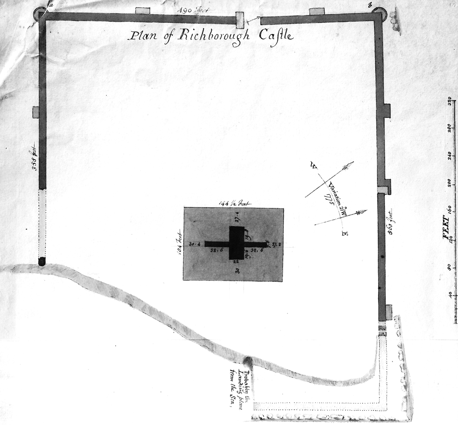
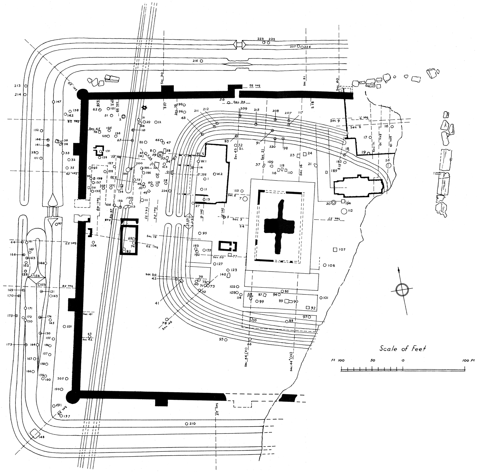
The position of the collapsed east wall at the foot of the slope has long been used to define the position of the former standing east wall. The first plan to show this interpretation is that published by William Boys as early as 1799 (fig. 2).Footnote 14 Bushe-Fox's first general excavation plan is the source for the way in which Cunliffe depicts the collapsed masonry off the north-east corner of the fort and the stylised fallen masonry on the east side (online fig. 1).Footnote 15 The dotted areas within Cunliffe's conjectured east wall line are recorded in Richborough I and II as ‘footings’.Footnote 16 These are described as ‘fragmentary patches of cobbles and chalk’.Footnote 17 In the same depiction in Richborough III all these features are unlabelled.Footnote 18 By the time of the publication of Richborough IV,Footnote 19 the collapsed east wall had been cleared sufficiently to provide an accurately surveyed plan, in the correct location, of the eight segments of walling of which this was comprised (fig. 3), and Bushe-Fox gives a terse account of the clearance, which is almost totally devoid of detail.Footnote 20 The omission from this plan of the ‘footings’ associated with the collapsed wall seen in previous versions may indicate that Bushe-Fox had abandoned their interpretation.
Plan of the Saxon Shore fort, projecting the line of the east wall (Boys Reference Boys1799).

Plan of the Saxon Shore fort in Richborough IV, showing the collapsed east wall segments as accurately surveyed (Bushe-Fox 1949, pl. xcix). (Society of Antiquaries of London)

Since the Bushe-Fox clearance the collapsed wall has been covered in dense vegetation (online fig. 2). In 2003 this was clearedFootnote 21 and photographic and measured records were made. The site was cleared again in 2008. Further recording was undertaken and excavation took place between the blocks of collapsed wall, in order to attempt to find the causes of the collapse and to establish the position of the ancient coastline.Footnote 22
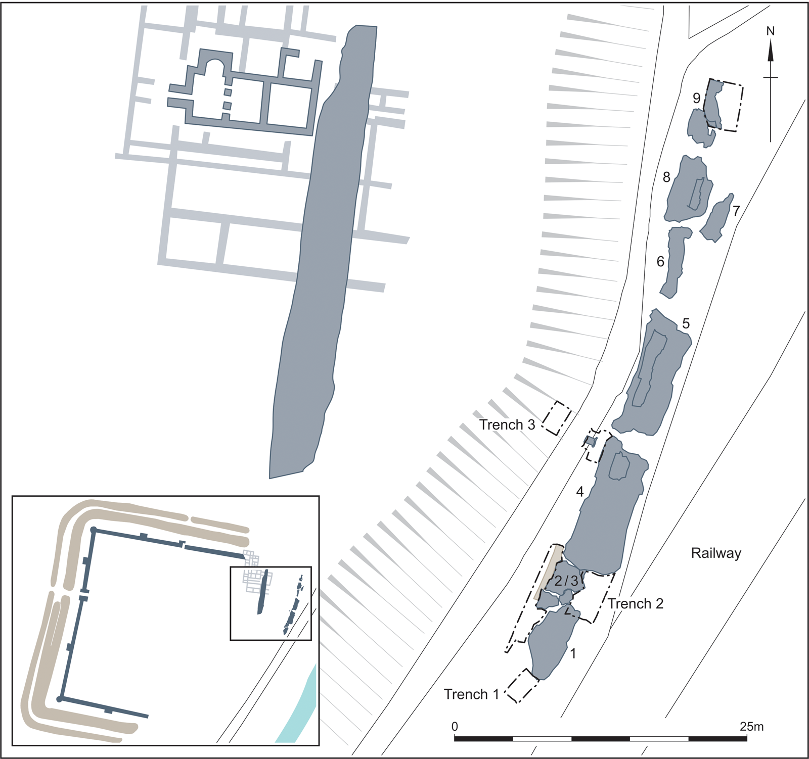
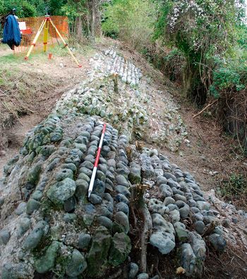
Nine blocks of collapse were recorded (fig. 4). Seven of these had fallen in an identical manner. Although fractured, they represent a single catastrophic episode. Visible dimensions are summarised in table 1. The blocks are substantial; the largest single block (Block 4) comprises a continuous unbroken length of walling of 11.70 m, while the original vertical height of the largest measurable section (Block 5) was 5.15 m – close to the height of the surviving north wall, which stands some 6 m high. The width at the original wall base was some 2.5 m. The composition of the material is identical to that of the standing wall: a core of concrete containing rubble in a variety of stone types, much of it reused from earlier buildings that were demolished in preparation for the building of the fort.Footnote 23 The exposed upper surface of the collapsed blocks represents the inner face of the fort wall. It is faced with large, coursed flint cobbles, and there are traces of two tile or brick bonding courses set 1.40 m apart (fig. 5).Footnote 24 The wall shows a slight (0.12 m) offset above the basal eight courses (0.82 m height). In Block 5 (fig. 5) there is an apparent vertical discontinuity, which may represent the join between two gang-lengths in the construction of the wall.Footnote 25 It is conceivable that the breaks between blocks also follow such discontinuities.
Plan of the fallen wall from excavations in 2008 (wall blocks numbered 1 to 9).

Collapsed wall Block 5, showing internal face coursing (including the basal offset and a vertical discontinuity) and the angle of repose of the collapse in plan.

DIMENSIONS AND ANGLE OF REPOSE OF BLOCKS OF FALLEN WALL

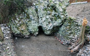
In several places, most extensively on Block 4 (fig. 6), the flat concrete base of the wall survives. Adhering to the concrete were many fragments of chalk. This is an important observation, as the foundations on which the fort walls stood were surfaced in a level layer of chalk, and it is clear that the collapsed wall represents the entire concrete mass that split off from the chalk foundation at the point of weakness created by the junction between the two materials.
Collapsed wall Block 4, showing angle of repose of the collapse. The flat mortar in the foreground is the base of the wall to which fragments of chalk adhered (the wall in the bank to the right is medieval, and was originally butted into the collapsed segment at the point where the original wall base has been cut back revealing the cobble core).

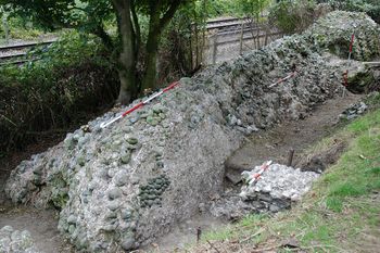
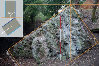
The most important aspect of the collapsed wall blocks is the relatively consistent angle of repose at which they lie (table 1). Fig. 5 shows the inner wall face of wall Block 5 in plan, showing the wall lying at a steep angle. Fig. 7 shows the collapse profile of Block 1. The horizontal breaks visible represent evidence for the construction of the wall in successive ‘lifts’. The same breaks are present, if slightly less visible, in fig. 8, which shows the collapse profile of Block 5. The overlain annotation in this illustration shows that the angle of repose of the wall is 36 degrees below the horizontal, meaning that the wall has collapsed in an arc of 126 degrees from its vertical position. This is a physical impossibility if the wall foundation lay immediately adjacent to the collapse. It is thus apparent that the concrete mass of wall has fallen from a foundation to the west and slid eastwards down slope. This fact alone nullifies the idea that the original fort wall stood where the collapse lies.
Segment of collapsed wall Block 1 in section, showing angle of repose. The wall in the foreground is medieval.

Collapsed wall Block 5 in section.

There was no sign in the collapse that this stretch of wall had included an interval tower opposite that on the western wall of the fort.
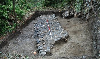
During the 2008 excavation, flint surfaces were found that appear to represent the ‘footings’ noted by Bushe-Fox in his 1926 plan in Richborough 1 (online fig. 1) and used to represent the foundation line of the east wall in the Cunliffe plan (fig. 1). These features are simply footpaths laid using either one or two courses of reused wall flints (fig. 9). That these are relatively recent is shown by the fact that they sealed 18th-century pottery.
Post-medieval path of laid flints, probably one of the features misinterpreted as footings by Bushe-Fox.

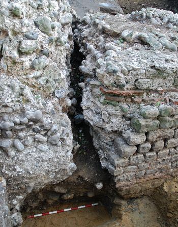
One block of wall collapse was different from the rest, and was clearly deposited before the wholesale collapse through a different process (Block 2/3; fig. 10). Prior to excavation this was thought to be an in situ standing wall, as it does sit vertically. The block is 2.91 m long, 2.45 m wide and stands 1.48 m high. It retains the facing of squared blocks and clear tile bonding courses (petit appareil), which appear more typical of the outer face of the fort wall. The inner face of the collapsed wall tends to be faced with flint cobbles, as is the case in Block 5. The facing stones comprise mainly chalk blocks, with a mixture of ragstone (20 per cent) and tufa (15 per cent). Two double tile or brick bonding courses are spaced 0.92 m (or seven facing courses) apart.Footnote 26 Two courses of facing survive, both above the top bonding course and below the bottom. Mortar bonding varies. At the top of the fragment this is the same white lime mortar that comprises the core, but at the base where surface pointing survives, this is of pink, brick-tempered opus signinum type mortar. This seems to be the only place where such pointing survives or has been recorded. If the visible west face is indeed the original east outer face, then this suggests that this piece has effectively somersaulted down slope from some height, suggesting that the opus signinum pointing must originally have been located at the top of the wall.Footnote 27 The block must have fallen with some force, as it was so embedded that when the rest of the wall collapsed it broke around the upstanding piece.
Collapsed wall Block 2/3. This fragment collapsed before the rest and settled upright in the soft fill of a linear feature.

Although access to the base of the upstanding piece was difficult, it did prove possible to examine the underlying deposits in a very limited area (fig. 11). The wall fragment had landed in the soft fill of the edge of a steep-sided linear feature which ran parallel to the wall, apparently running to a butt-end to the north, 0.60 m to the south of the end of Block 2. Following the collapse of the wall fragment, the edge of this linear feature became sealed by slumping of the natural sand from the slope above to the east, and this slumping also banked up against the wall fragment. In the fill of the linear feature was a small quantity of pottery dating to the third to fifth centuryFootnote 28 and two coins, one a radiate or nummus (a.d. 260–402) and the other an issue of Valentinian II (a.d. 388–92).Footnote 29 This coin was recovered from beneath the wall fragment, and, for the first time, provides a terminus post quem for the first phase of wall collapse.
Section of the edge of the linear feature beneath collapsed wall Block 2/3.

THE ‘UNFINISHED’ WALL FOUNDATION
The status of this foundation as ‘unfinished’ or ‘abandoned’ is a major plank in the argument for the received plan. Cunliffe concluded that ‘the footing was prepared in error, but for some reason never used, and the wall was, in fact built further east’. Three arguments are advanced for this conclusion: the first relates to the spatial relationship of the foundation with the conjectured north-east interval tower, discussed below; the second to the apparent fact that there was no sign that a wall had been built upon the foundation; and the third relates to the stratigraphic position of the foundation in relation to two dated pits.Footnote 30
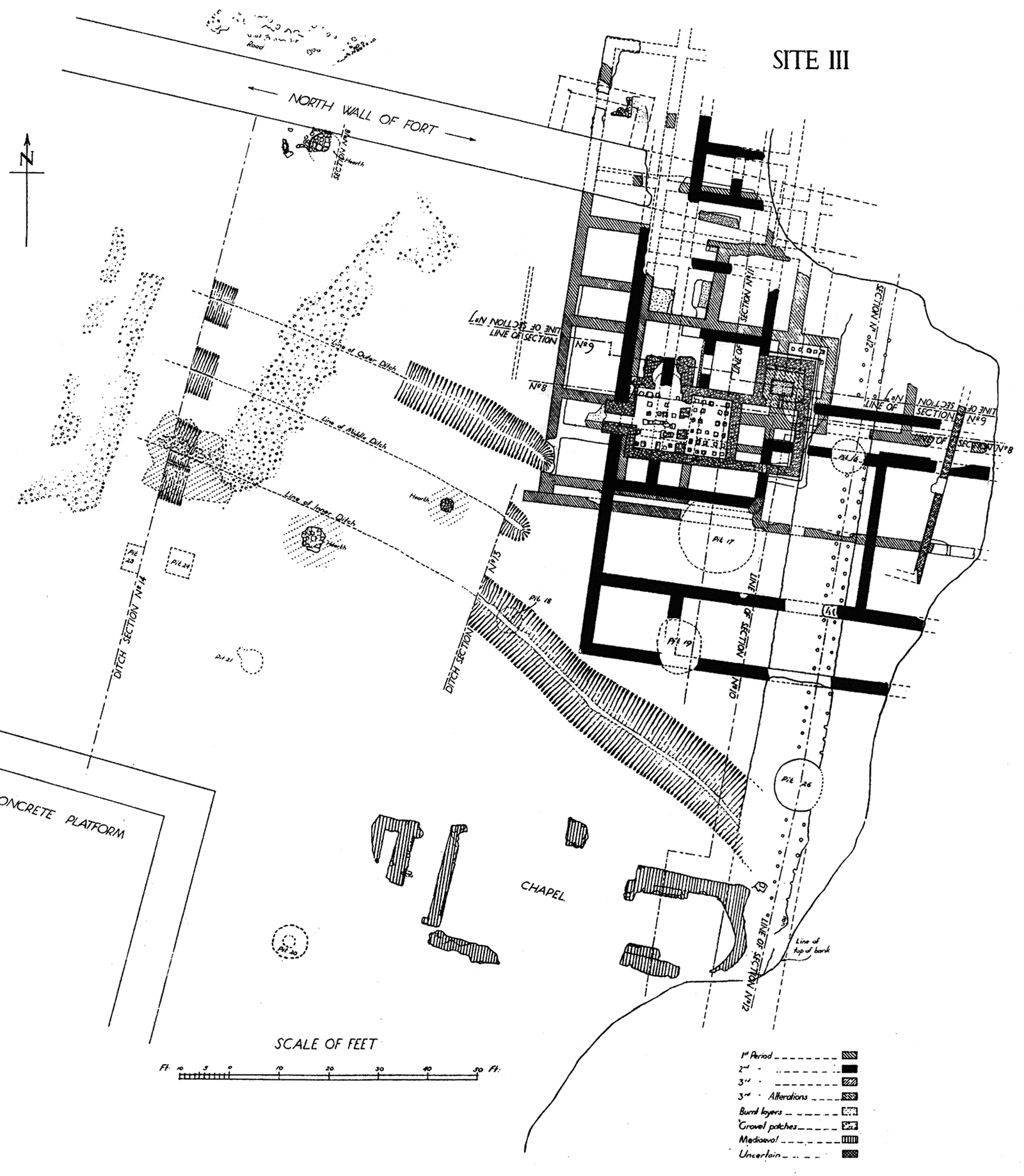
The foundation was discovered and excavated as part of Bushe-Fox's Site III (fig. 12),Footnote 31 where a complex structural sequence was excavated. In summary, the earliest structures were three phases of a timber building,Footnote 32 which was replaced in the late first century by a stone-founded building, possibly a courtyard house. This building included a small heated bath, opus signinum floors and painted wall-plaster.Footnote 33 Together with both its timber predecessor and stone-built successor this is interpreted as forming successive phases of a mansio.Footnote 34 This middle-phase building was levelled to its foundations and its larger stone-built successor was built over the demolition debris, probably in the first half of the second century.Footnote 35 In the late third century an area around the quadrifons arch was enclosed by three ditches and a rampart. The mansio clearly remained in use during this phase, as the two outer ditches butt-ended to the west of its west wall, while the inner ditch skirted the south-west corner of the building (fig. 12).Footnote 36 The extent of this building, conceivably again a large courtyard building, is unknown, as its northern and eastern ranges have collapsed through erosion. The walls survive only as far as the eroded edge of the eastern slope.
Detailed plan of Bushe-Fox's Site III (Bushe-Fox 1928, pl. xxxix). (Society of Antiquaries of London)

The ‘unfinished’ foundation, of which a length of some 42 m survive, can best be described in Bushe-Fox's words:
[The foundation] consisted of a packing of stones – mostly water-worn flints – 1 ft. to 2 ft. [0.30 to 0.60 m] deep and 13 ft. to 14 ft. [3.96 to 4.26 m] wide, capped with a carefully-levelled layer of chalk a few inches thick. The cavities left by the decayed wood of two parallel rows of vertical piles some 3ft. to 4ft. [0.91 to 1.23 m] apart were discovered running the whole of its length. These piles, which had been embedded in the stone packing and did not penetrate through its surface, varied from 9 in. to 14 in. [0.22 to 0.35 m] across at the top, tapering to a point at the bottom, having been driven some 4 ft. [1.23 m] into the soil below. It will be seen by referring to Section 12 that the level of the foundation varied considerably. This can be accounted for if the builders only considered it necessary to lay it at a uniform depth beneath the existing surface-level, which was probably higher over the ruins of the building on Site III, where there must have been an accumulation of building rubbish, than to the south, where no buildings had existed. The walls of the second house had been destroyed to their present level before the laying down of the foundation; but their presence was known, as the changes in level coincided with them in each instance, and two had been lowered to conform approximately to the surface of the chalk capping. In no case was the packing of stones carried over any of these walls. The northern portion was much destroyed, but some of the chalk capping was in situ and there can be little doubt that it had been only 1 ft. [0.30 m] thick and not 2 ft. [0.60 m] as elsewhere … The southern portion could not be completely examined owing to the presence of the apse of the chapel above, but it was traced to the edge of the bank both at this and the northern end, where in each instance it had a ragged end, having been broken away by the erosion of the site.Footnote 37
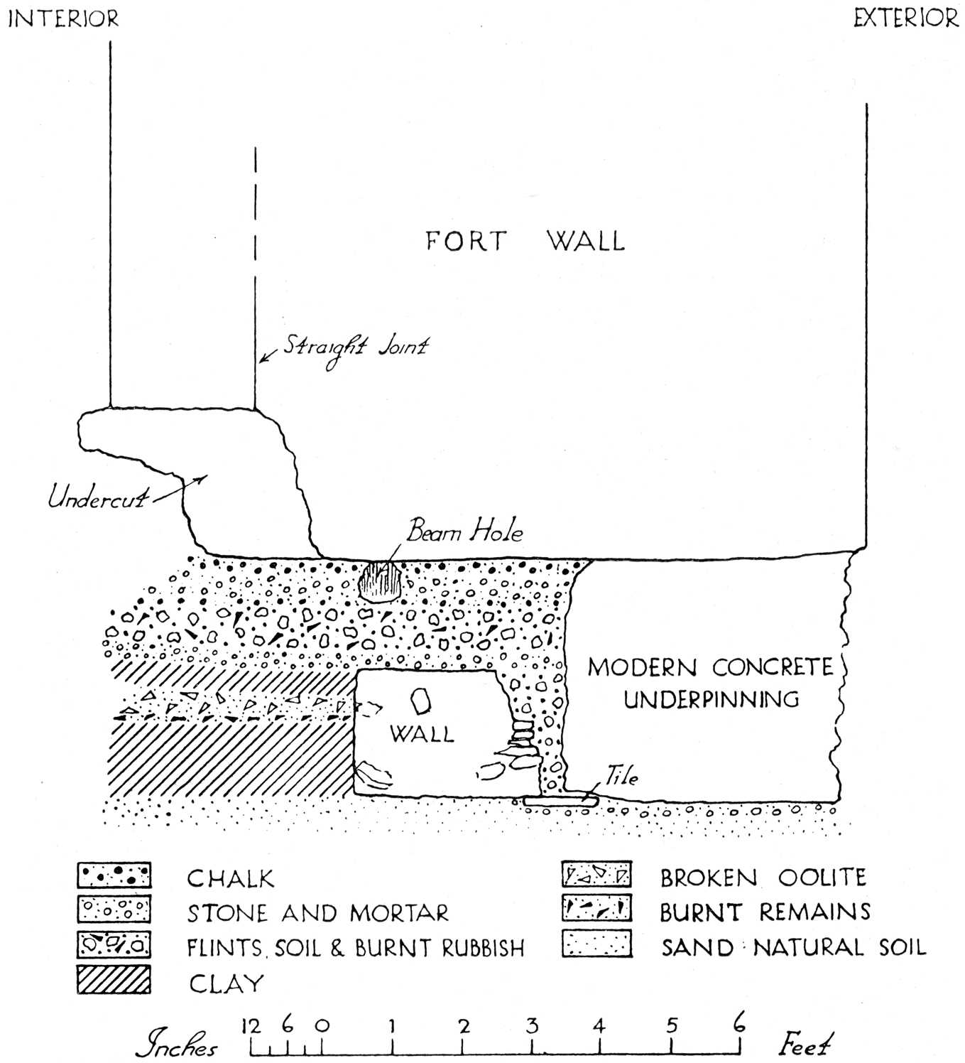
To assess this feature it is necessary to compare it with the foundations of the standing walls. In the few (for obvious reasons) places where these could be observed, they are set in foundation trenches 0.76 to 0.91 m deep and comprising packed rubble stone with a surface packing of chalk. A layer of horizontal timber strapping is represented by beam-voids showing timber scantling measuring 0.2 by 0.15 m, which was sealed by a further layer of stone and chalk capping.Footnote 38 The foundations of the west wall comprise from the base 0.30 m of flint cobbles in soil, 0.05 m of rammed chalk, a further 0.15 m of loose flints and 0.05 m of rammed chalk capped with mortared chalk, a total depth of 0.55 m. The text does not mention provision for horizontal timber strapping, though this is represented in the published section.Footnote 39 The eroded east end of the north wall was examined, and the section published (fig. 13).Footnote 40 Here the fort wall was built across one of the demolished walls of the mansio building. The section suggests that clay was piled against the earlier wall and then levelled off with mixed stone and mortar, and capped with chalk, within which is the socket of a longitudinal beam. The total depth of the foundation seems to have been 0.48 m. There was no indication of driven timber piles, and the same is true of the foundations of the east end of the south wall.Footnote 41
Section under the north-west corner of the standing fort wall (Bushe-Fox Reference Bushe-Fox1928, 23, pl. xlv). (Society of Antiquaries of London)

The double row of piles is situated on the eastern side of the ‘unfinished’ foundation. This suggests that this side required substantial additional foundational support. It is possible that the foundation was relatively close to the edge of the plateau when constructed, and that the risk of collapse was recognised and mitigated against by the use of the piles. As Stephen Johnson notes,Footnote 42 there is a considerable difference in level between the foundation at its northern end, where it was laid over the foundations and levelled demolition debris of the earlier buildings, and the southern end, where the foundation lay over the soft fill of the inner ditch of the triple-ditched enclosure around the quadrifons arch (fig. 12). Despite these changes of level, the timber piles were employed along the full length of the foundation (fig. 12), and these level changes must have been considered acceptable while the not-inconsiderable effort of pile-driving was taking place. It is possible that differences in the underlying stratigraphy were a further reason for the use of stabilising piles.
Assuming that this wall was laid out as part of the original planning of the fort, it might be expected that it would include the foundation for an interval tower opposite the one on the equivalent wall to the west. The fact that there is no such foundation suggests that no such tower was planned.
One of the chief reasons for believing the foundation to have lain unused relates to the numismatic contents of two pits that cut through it: Pit 16 and Pit 26 (figs 12, 14). Pit 16 was ‘33 ft [10.06 m] in depth below modern surface level, and 8 ft [2.43 m] in diameter. The filling consisted almost entirely of building rubbish.’Footnote 43 The ten coins contained within this pit are listed in the publication,Footnote 44 which replicates exactly the coin list as it appears in the original site notebook (online table 1).Footnote 45 Despite some elements of residuality, the presence of a coin of Honorius (388–95) at the base of the pit, at a depth of 22 ft 6 ins (6.85 m) provides a terminus post quem of the late fourth century for the primary silting or filling of the pit.
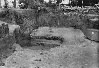
Photograph of Pit 26 during excavation (labelled ‘C’).

Pit 26 has been cited as one of the principal pieces of evidence for the foundation being ‘unfinished’. The pit was
12 ft [3.66 m] in diameter and 24 ft 9 in [7.54 m] deep measured from the top of the supposed foundation of the east wall of the Saxon Shore fort through which it had been cut [fig. 14]. There were indications that the ground level when this pit was dug was at least Footnote 46 3 ft above the top of the foundation and that the mouth had been filled with stones and building rubbish, among which was a coin of the radiate head type.Footnote 47
This description is followed by a coin list. The published list describes a tightly dated group of coins, mostly of the third century with nothing later (online table 2), and Bushe-Fox, on this evidence, gives the earliest possible date for the filling of the pit as 268 and the latest as ‘not much after 296’.Footnote 48 Cunliffe's important synthesis of the development of Richborough in Richborough V (1968) gives a Carausian date (286–93) for the dismantling of the triple-ditched fort and the construction of the Saxon Shore fort.Footnote 49 Of the relationship between the ‘unfinished’ foundation and Pit 26 he states that:
the footing was cut by Pit 16, containing late fourth-century coins, and by Pit 26, which was not later than the end of the third century. The last piece of evidence clearly suggests either that the wall had already disappeared by the date of the pit – an improbable conclusion – or that it had never utilised the footing; and since there is ample evidence of a collapsed east wall below the cliff, the conclusion must be that the east wall was constructed, but not on the chalk footing. The simplest explanation is that the footing was prepared in error but for some reason never used, and the wall was, in fact built further east.Footnote 50
When applied to the stratigraphic sequence, the dating advanced makes little sense. The ‘unfinished’ foundation was built across the backfill of the inner ditch of the triple-ditched enclosure. The terminus post quem for the filling of the ditch is c. 273.Footnote 51 The absence of Carausian coins in these backfill deposits, combined with the presence of frequent coinage of this date in deposits considered to relate to the primary occupation of the stone fort, has led to the conclusion of a Carausian construction date,Footnote 52 though the same evidence leads Johnson to conclude that the construction of the stone fort immediately pre-dates Carausius, ‘within the decade immediately before 285’.Footnote 53 If the ‘unfinished’ foundation was intended as the location of the east wall of the fort, then, logically, it would have been laid out at this time and the terminus post quem for this would be identical to that for the filling of the triple ditch. The photograph of Pit 26 (fig. 14) shows the cut through the chalk foundation, but to the left of shot the remaining pit fill may be seen in section up to a height of some 2 ft (0.61 m) (judging by the scale of the ranging rod in the background), with an excavated void above. It seems that upper filling has been removed down to this level, and this removed material was probably the upper fill of ‘stones and building rubbish’ noted by Bushe-Fox, but clearly absent from this image. The pit measured 24 ft 9 ins (7.54 m) in depth from the level of the chalk footing, but in the original manuscript coin list the base is at 26 ft (7.92 m).Footnote 54 This discrepancy of 0.38 m is partly accounted for by the pit being cut from a higher level than the footing, but Bushe-Fox (above) gives the level from which the pit was cut as at least 3 ft (0.91m) above the footing, and this is confirmed by the photograph. This means that before this 8 to 9 m-deep pit was dug, a depth of material of a metre plus was either dumped or had accumulated over the foundation. The pit was then excavated, possibly for use as a well.Footnote 55 The filling of the pit then took place. The published coin list from Pit 26 contains entirely pre-Carausian coinage, exactly like the fill of the triple ditches. As noted above, Bushe-Fox gives the filling date as between 268 and 296;Footnote 56 Johnson gives a fill date of ‘the last quarter of the third century (if not a trifle earlier)’Footnote 57 and also suggests that the site of the wall foundation was ‘soon forgotten’ as, if not, the pit ‘would probably not have been deliberately sunk through the foundation of flints and chalk 2 ft (0.61 m) thick.’Footnote 58
The sequence is thus supposed to be as follows. Sometime between c. 273 and 285 the triple ditches were backfilled and work began on the construction of the stone fort, including the laying of a stone and chalk east wall foundation, reinforced by two rows of driven timber piles 1.23 m long (of which the sockets for 56 survived in the short length excavated). Immediately upon the completion of the considerable labour expended on this foundation it was abandoned, having been built by mistake, in favour of a replacement some 25 m further east and at a lower level. After its abandonment, it was sealed by over 1 m of horizontal stratification and totally forgotten, before an 8 m-deep shaft was first dug through it and then backfilled. This whole sequence was completed within 20 years, ending shortly after c. 296. This is inherently unfeasible.
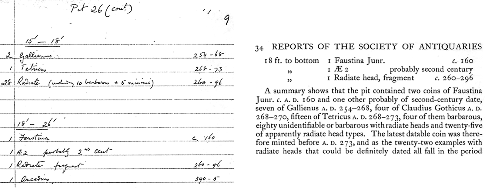
Philip Smither's research involves examination of the original excavation notebooks. In the course of this work he has looked at the coin catalogue records from 1924 to 1925, including the original coin list for Pit 26. The original manuscript list is presented for comparison in online table 2. This shows that the lists are virtually word-for-word identical, and the identifications made in the site notebook are repeated in the published list. The coin totals for each 3 ft excavation depth unit are identical, except for two cases. In the 6–9 ft unit a barbarous radiate of Tetricus which does not appear in the original list is added and, crucially, at the bottom of the pit a coin of Arcadius listed in the original record is omitted from the published list. Fig. 15 compares the published list from the bottom of the pit to the manuscript list, and it is striking that, apart from the omission of the Arcadius coin, the published list is copied verbatim from the notes. The reason for the omission emerges from a letter written by the numismatist J.W.E. Pearce to Bushe-Fox on 3 November 1925, which was pasted into the site notebook.Footnote 59 Pearce added a postscript: ‘It's rather annoying that an Arcadius should have got into the bottom layer of Pit 26. I suppose it followed the diggers down, or was put into the envelope by mistake.’
The coin list from the base of Pit 26: (left) from the original site notebook and (right) from the published report (Bushe-Fox 1928, 34). Note the absence of the Arcadian coin from the published report.

This assumption, that the Arcadius coin is intrusive, is clearly based upon the fact that it did not, in Pearce's mind, fit with the assemblage of third-century coins that forms the majority from the pit group. It is an example of special pleading based upon the assemblage alone with no regard to context. This conclusion was accepted by Bushe-Fox, and the Arcadius coin thus escaped publication.
All the stratigraphic problems regarding Pit 26 can be resolved if we reverse Pearce's assumption, and accept that the Arcadius coin was found in situ, and that all the other coins in the pit are residual.Footnote 60 This would mean that both pits cutting the foundation, Pits 16 and 26, have late coins in their primary fill and that backfilling in both cases cannot have begun until after 395. The fill of Pit 26 contained very little pottery, and, in contrast to Pit 16 and others in the area, contained ‘very little building rubbish’,Footnote 61 although it was sealed at the top with such material. If the two pits are both late fourth century or later in date, then clearly the east wall could have been built on the foundation, and the idea that ‘the wall had already disappeared by the date of the pit’Footnote 62 becomes far less improbable.
Pit 26 lay 20 ft (6.09 m) to the north of the excavated remains of the medieval chapel of St Augustine, and burials associated with the chapel, though disturbed, extended at least 6 ft 10 ins (1.82 m) north of the chapel building.Footnote 63 Comparison of two published sectionsFootnote 64 that share a common datum line allows the relative levels of these features to be determined (all values have been converted from feet). The south end of the chalk foundation was 10.62 m above Ordnance Datum, and the bottom of the chapel foundation 11.9 m above Ordnance Datum, a difference of 1.33 m. Bushe-Fox's statement that Pit 26 was cut from a level ‘at least three feet’ (0.91 m) above the level of the chalk foundation suggests that it was cut from a broadly similar level to that from which the chapel was constructed. This immediate area was a focus of medieval activity; directly beneath the chapel, at the level of the collapsed wall, predominantly medieval finds and some structures of the same date were found.Footnote 65 The possibility should be considered that Pit 26 was a medieval feature and that all the coins within it, including the Arcadius, were residual and derived from reworked Roman material used to backfill the well. It is entirely probable that the wall collapse itself took place in the post-Roman period.
THE CONJECTURED NORTH-EAST INTERVAL TOWER
A further argument for the east foundation being unused was advanced by Cunliffe thus:
elsewhere on the [walled] circuit the rectangular bastions were placed midway between the gates and the corner turrets, but if this [the ‘unfinished’ foundation] were the east wall, then the adjacent bastion [ie the interval tower] on the north wall would come too close to the north-east angle.Footnote 66
As noted above, the tower to the west of the north postern gate is not midway between the gate and the corner tower. On the contrary, there is a 10 m difference in the distance between the corner tower and the interval tower and the distance between the interval tower and the postern. The distance between the postern gate and the site of the conjectured interval tower is 47 m. The distance between any corner tower at the junction between the ‘unfinished’ foundation and the north wall would indeed be unacceptably close to the conjectured interval tower – they would be only about 12 m apart. This fact was an important driver to the positioning of the projected corner tower on Cunliffe's plan at the base of the scarp next to the collapsed wall.
The interval and corner towers were cleared and examined in 1922–23,Footnote 67 and in both Richborough I and II the towers are shown on site plans in the same way – with differing outlines depending on the certainty of interpretation (online fig. 1).Footnote 68 In the site reports from Richborough III onward, all the obviously extant towers are shown as definite, in solid black, while the postulated south postern gate, for which some suggestive evidence exists,Footnote 69 is shown as a single dashed outline (as are all conjectured walls and towers except for the north-east interval tower in the plans in Richborough IV (fig. 3) and V (fig. 1)). In all cases, the postulated north-east angle tower is represented uniquely by a double-dashed outline.Footnote 70 No explanation for this appears in any legend on any plan.
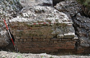
In fact, the existence of this interval tower can be questioned, and it is possible that doubts over this explain the way in which it has been depicted. All the definite interval towers were built bonded into the curtain wall of the fort. Most of these are robbed, but this has universally left scarring on the face of the curtain wall where the side walls of the towers were bonded in (fig. 16, online figs 3, 4). Although there is a difference in the curtain-wall facing on the supposed site of the north-east interval tower, there is no even scarring from the removal of a bonded tower (fig. 17).Footnote 71 The uneven appearance of the scarring is no different from examples of similar scars on the interior face of the fort wall (online fig. 6). Similarly, for all the other corner and interval towers substantial foundations have survived (fig. 16, online figs 3, 4, 5). On fig. 12, the published plan of Bushe-Fox's excavations of Site III, though the double-dashed outline of the supposed tower is overlaid on the plan, there is no reference to the tower being located archaeologically, and neither the excavation plans nor the photographs show any foundations that might have belonged to the supposed tower. What was found, however, were the footings of the earlier mansio, which occupy the space where the tower foundations might have been expected.
The south tower of the west wall, showing the scars of the robbed side walls, the base of the tower and the interrupted tile courses.

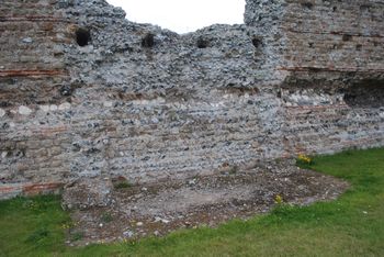
The face of the fort wall at the position of the conjectured interval tower.

In the upper part of the wall face, three tile courses are interrupted on either side of this different facing, but it is important to note that the bottom tile course is continuous and unbroken below the rough facing (fig. 17). In the case of the south tower on the west wall (fig. 16) and the east tower on the south wall (online figs 4, 5), all the tile courses, including the bottom one, stop on both sides of the tower, and the tile courses are turned to be continuous around the face of the tower. Had a similar tower been provided here, this tile course would be broken either by omitting it or at least showing a bonding scar with a side wall. This does not appear. On the contrary, above the basal tile course the facing is flush with that to the west, even though the next tile course is intermitted (online fig. 7). This has more the appearance of a repair to the curtain wall, something that appears frequently elsewhere on the circuit (online fig. 6).
The traces of this conjectured tower are therefore different from those of all the other towers on the curtain wall. This summary shows that there is debateable structural and no stratigraphic evidence for the existence of the interval tower.Footnote 72 The idea of a tower here clearly results from the change in the facing at this point, and this is probably why it appears on the earliest reliable plan of the fort drawn by Boys in 1799 (fig. 2), though it is also possible that Boys saw a part of the earlier building beneath the wall and interpreted this as the footings of an interval tower.
TOPOGRAPHICAL CHANGE
That topographical change has taken place on the eastern side of the fort is obvious from the position of the scarp and the loss of a substantial part of the area of the fort. This is conventionally attributed to marine erosion taking place during the time when the Wantsum channel was open to the sea, and this is certainly the most likely explanation. During the 2008 excavation, foreshore deposits, including water-worn Roman ceramics, were encountered immediately adjacent to the fallen wall. The evidence shows that, even after considerable silting in the 14th century, the residual channel of the Wantsum (or the course of the river Stour) followed the line of the wall collapse. Two segments of collapse were linked by a medieval wall which formed a small inlet or dock beneath St Augustine's chapelFootnote 73 into which medieval pottery was deposited. Bushe-Fox also noted rows of medieval tiles and ‘medieval pottery in larger quantity’ than Roman in this location.Footnote 74 It is at yet impossible to state where the coastline lay at the time of the Saxon Shore fort; in all likelihood, based on available evidence, this was close to the fort. If this was indeed the case, the proposed east wall on the Cunliffe plan would effectively have been on the beach. The foreshore deposits lay at 1.23 m above Ordnance Datum, while the standing fort walls lay approximately on the 10 m contour. If the east wall was adjacent to the collapse, then the fort would have had to have been built on two levels, with the foundations of the north and south walls terraced down a slope with a vertical height of 9 m. The known, excavated foundations of the north and south walls are level, and only 0.76 to 0.91 m deep. No signs of deeper foundations towards the scarp edge have been recorded.
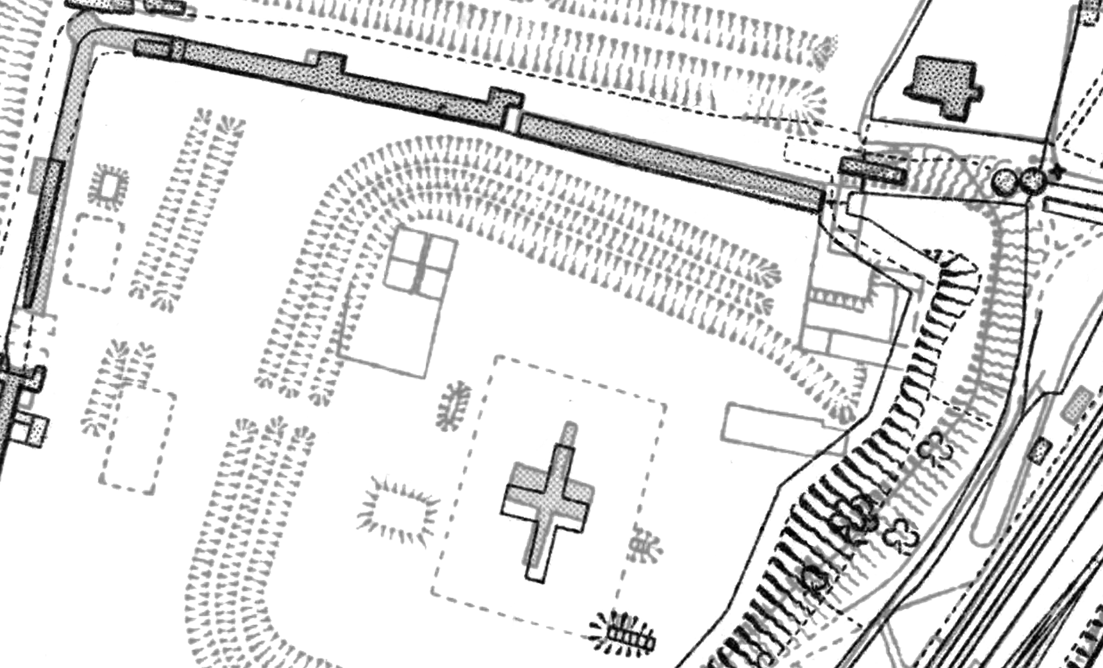
The scarp edge was further altered by Bushe-Fox. Comparison of his plans with the situation on the ground today shows that the eroded ends of the east–west walls of the mansio complex are now some 13 m from the scarp edge, whereas the excavation plans show the wall ends at the edge. This contrast is also seen when comparing the 1:2500 Ordnance Survey maps of this part of the site from 1907 and 1945 (fig. 18).Footnote 75 This additional ground was clearly the result of the dumping of excavation spoil during the 1920s and 1930s.Footnote 76
The north-east corner of the fort on the 1945 1:2500 Ordnance Survey map (grey), with the 1907 map overlain. Note the difference in the position of the scarp edge resulting from the deposition of Bushe-Fox's spoil.

REVISED PLAN
It is the conclusion of this paper that the ‘unfinished’ foundation was, in reality, the foundation for the built east wall of the Saxon Shore fort.Footnote 77 Cunliffe advanced three arguments against this conclusion, all of which have been challenged above.Footnote 78 Firstly, the debatable evidence for the conjectured interval tower, and particularly the morphology of the bottom tile course, removes the problem of its proximity to an angle tower at the junction of the foundation with the standing north wall. Secondly, the collapsed wall fell as a single block. The chalk adhering to the concrete base shows that it split from the foundation at the junction between foundation and superstructure, leaving, as Cunliffe observes, no in situ evidence that a wall had been built on the foundation.
The new evidence regarding the angle of repose of the fallen wall only makes sense if the wall split from its foundation and then slid down slope from the west. The vertical difference between the upturned base of the collapsed wall and the foundation is 6.76 m, the horizontal distance, 23.5 m, giving a potential average natural slope of 16.05 degrees; however, the angle of repose of the fallen wall, between 22 and 45 degrees shows that the actual eroded slope was much steeper, though this is hidden today by spoil dumping in the 1920s and 1930s.
The final argument is the difficult issue of the apparent third-century date of the filling of Pit 26. The problems here are resolved if the coin of Arcadius, so airily dismissed by Pearce, is reinstated as an actual site find as originally recorded. This means that a wall could be built on the foundation in the late third century, only to collapse in the late fourth century (at the very earliest) or in the 11th to 12th century (at the very latest, as the chapel of St Augustine of this date overlies the foundation). Further, the proximity of the feature to the chapel and the level from which it was cut raises the real possibility that the feature is medieval and that all the Roman finds are residual.
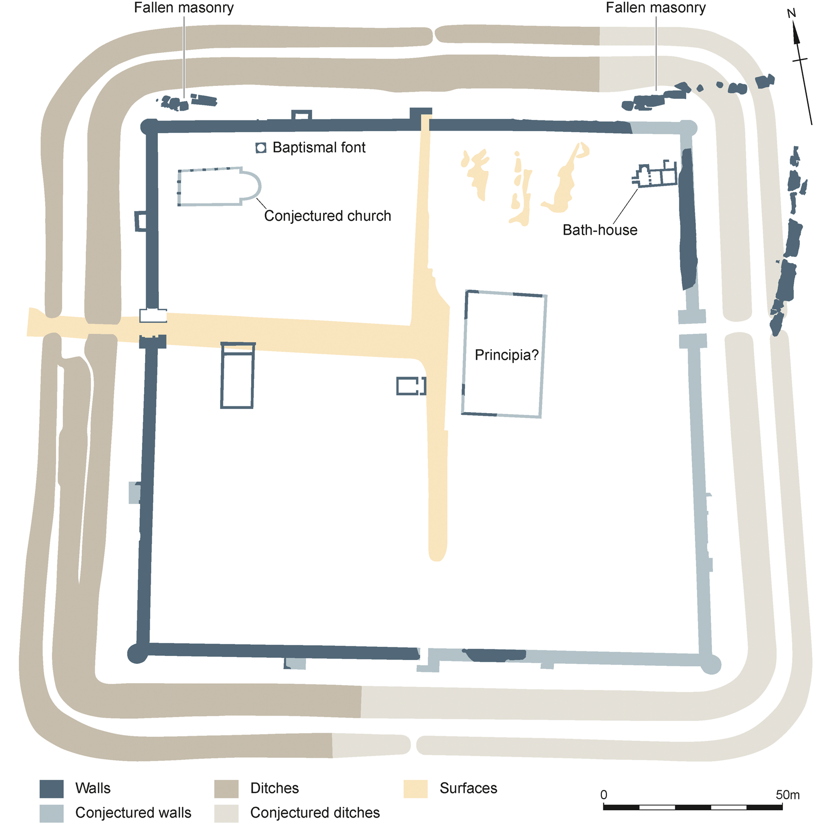
If the east wall of the fort stood on the excavated foundation, ideas of the construction and plan of the fort must change (fig. 19). First, it is no longer necessary to see it as having been terraced or built on two levels; on the contrary, it was constructed on a level plateau. It seems that it was built close to the edge of the plateau, and that the danger of subsidence was recognised and mitigated by reinforcing the east edge of the foundation with timber piles – an expedient apparently not employed on the other three sides. Proximity to the edge of the plateau was not driven by a lack of space or the existence and retention of pre-existing structures. This is shown by the fact that substantial buildings were demolished in order to build the fort. There must have been a strong incentive to build in this position, and this is most likely to have been the desire to dominate a nearby waterfront and probable port facilities, evidence for which is now lost to the railway line, the river and the silting of the Wantsum.
New plan of the Saxon Shore fort of Richborough.

The north-east corner of the fort, presumably represented by a circular tower, would have been at the junction of the ‘unfinished’ foundation and the north wall, at a distance from the postern gate of 73.25 m; this is only 2 m more than the distance between the gate and the north-west angle tower. Unlike the wall to the west of the postern gate, the eastern stretch was not provided with an interval tower.
The distance between the north-west corner tower and the portal of the main west gate is 53.5 m. The collapsed parallel wall on the east side survives to a length of 53 m overall. This similarity in length strongly suggests that the collapsed wall is the exact counterpart of the west wall – a stretch between a corner and a gate opening that collapsed as a single unit. This further suggests that there was also a principal east gate opposite the west gate; this would have been a logical necessity for access to the shore and harbour.
The linear feature into which the first, upright, piece of wall collapse fell ran nearly parallel to the wall. Furthermore, the apparent butt end of the feature lies exactly opposite the butt ends of the double ditches at the west gate, further suggesting the presence of an east gate. The distance between the edge of the feature and the ‘unfinished’ foundation is identical to the distance between the west wall of the fort and the inner edge of the outer ditch (24.8 to 25 m), and it is therefore suggested that this feature represents the outer ditch carried around the eastern side of the fort. The Valentinianic coin beneath the collapse fragment is consistent with Bushe-Fox'sFootnote 79 summary table of coinage from the ditches generally showing that all three divisions of fill – lower, middle and upper – contained both Valentinianic and Theodosian coinage in some quantity.
On the western wall there is an interval tower between the north-west angle and the gate, but there is no sign of a counterpart in the form of a collapsed interval tower on the eastern side or of the provision for such a tower on the ‘unfinished’ foundation. Had such a structure existed, the pattern of collapse would surely be disturbed, as it would underlie the curtain wall. Given that there was no interval tower on the north wall to the east of the postern gate, this suggests that interval towers were provided on the landward side of the fort, to the west of the postern gate(s) only.
INTERNAL STRUCTURES
The foregoing discussion shows that the received view of the dimensions of the fort must be changed and that the ‘unfinished foundation’ was the actual foundation of the east wall. This paper would not be complete without a brief discussion of the internal fort buildings. This is an area in which there are considerably fewer grounds for certainty, and, therefore, much of what follows is speculative.
A few structures certainly belong to the Saxon Shore fort period. The best dated is the small bath-house in the north-east corner of the fort. Accepting the proposed new plan for the defences, this building would have been tucked neatly against the east wall of the fort. In the centre of the fort the two stone-founded buildings marked on figs 1 and 19 are certainly from the Saxon Shore fort period. In the north-west corner is a tile-built structure,Footnote 80 now interpreted as a baptismal font,Footnote 81 and a structure based on a series of rectangular stone blocks. The latter can be interpreted either as supporting lean-to buildings against the interior corner of the fort walls or as a free-standing structure which, through association with the font, is interpreted by P.D.C. BrownFootnote 82 as a church. The existence of the font presupposes the presence of a church, and it is also the case that the font would have been enclosed within a baptistery building. Brown's speculative interpretation, which is tentatively illustrated in fig. 19, is one of several possibilities and has not achieved general acceptance.
The east–west road was remetalled and a central drain was added during this period;Footnote 83 the roads running from the north postern southwards, beyond the east–west road, were also resurfaced.Footnote 84 In the centre of the fort, a rectangular walled structure was found on top of the foundation of the quadrifons arch in 1865, and acknowledged as being later than the cruciform remnant of the monument.Footnote 85 This was considered by Ian Richmond,Footnote 86 who concluded that these walls were foundations to a structure sealing the monument foundation, with a floor level consistent with that of the other fort phase buildings. He further suggested, based on the central position of this structure, that it was the principia of the fort. This perhaps deserves some consideration, as the location of the building with relation to the east–west and north–south roads is identical to that of the principia of earlier forts with relation to the via praetoria and via principalis. If this was the principia, the west gate would be the porta praetoria, and the fort, therefore, would have been planned to ‘face’ west. This would also make some sense of the apparent provision of interval towers in the ‘front’ half of the fort, and only to the west of the via principalis. The implication would be that the fort had a defensive posture on the landward side, in contrast with other Saxon Shore forts where such orientation can be determined, namely the early forts at Caister, Brancaster and Reculver, all of which ‘faced’ the sea.
SUPPLEMENTARY MATERIAL
For supplementary material for this article, please visit https://doi.org/10.1017/S0068113X20000379.
The supplementary material comprises tables of the coins from Pit 16 and Pit 26, and additional figures.
ACKNOWLEDGEMENTS
This paper is an extended version of one presented by Wilmott at the 24th International Limes Congress, Viminacium, Serbia, September 2018. The authors wish to thank the anonymous referees, whose comments have enhanced the paper, and John Vallender for creating and formatting the illustrations.