


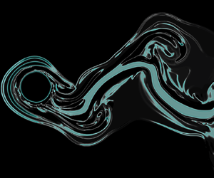



1. Introduction
Vortex-induced vibration (VIV) is a model problem in fluid–structure interactions, in which a flexibly mounted or a flexible bluff body oscillates due to fluctuating forces that act on it from the vortices that are shed in its wake. During VIV, the oscillation frequency and the shedding frequency are synchronized, and ‘lock-in’ is observed. If a flexibly mounted rigid body is allowed to oscillate in the direction perpendicular to the direction of flow, crossflow VIV is observed (Sarpkaya Reference Sarpkaya2004; Williamson & Govardhan Reference Williamson and Govardhan2004), in which large-amplitude oscillations (with a magnitude of an order of the diameter of the cylinder) occur over a range of reduced velocities (defined as  $U^*=U_\infty /(f_n D)$, where
 $U_\infty$ is the incoming flow velocity,
 $D$ is the cylinder's diameter and
 $f_n$ is the natural frequency of the structure in the air). If the degree of freedom is in the direction of flow, responses are observed over two ranges of reduced velocities (inline VIV), and the magnitude of response is about 10 % of the cylinder diameter (Cagney & Balabani Reference Cagney and Balabani2013a,Reference Cagney and Balabanib; Gurian, Currier & Modarres-Sadeghi Reference Gurian, Currier and Modarres-Sadeghi2019). The inline and crossflow VIV responses survive even at relatively large deviations from a pure inline or a pure crossflow direction (Benner & Modarres-Sadeghi Reference Benner and Modarres-Sadeghi2021). If the cylinder is free to oscillate in both the crossflow and inline directions, then figure-eight trajectories and higher harmonics in the flow forces are observed (Dahl, Hover & Triantafyllou Reference Dahl, Hover and Triantafyllou2007; Dahl et al. Reference Dahl, Hover, Triantafyllou and Oakley2010; Carlson, Currier & Modarres-Sadeghi Reference Carlson, Currier and Modarres-Sadeghi2021). Vortex-induced vibration can also be observed in long and flexible cylindrical structures (Bourguet et al. Reference Bourguet, Modarres-Sadeghi, Karniadakis and Triantafyllou2011; Seyed-Aghazadeh & Modarres-Sadeghi Reference Seyed-Aghazadeh and Modarres-Sadeghi2016; Gedikli, Chelidze & Dahl Reference Gedikli, Chelidze and Dahl2018; Seyed-Aghazadeh, Edraki & Modarres-Sadeghi Reference Seyed-Aghazadeh, Edraki and Modarres-Sadeghi2019; Bourguet Reference Bourguet2020). In these cases different modes of the structure can be excited and transitions from one mode to another mode as well as multimodal excitation (where more than one mode is excited at the same time) are observed. Since flexible structures are allowed to oscillate in both the crossflow and inline directions, figure-eight trajectories are observed at their cross-sections.
To better understand the responses of a flexibly mounted cylinder placed in flow, and to explore several possible combinations of the incoming flow velocity, amplitude of oscillations and frequency of oscillations, several studies have been conducted on cylinders that are forced to oscillate in incoming flow with prescribed amplitudes and frequencies. Sarpkaya (Reference Sarpkaya1977) conducted experiments of uniform flow past a sinusoidally oscillating rigid cylinder at high Reynolds numbers ( $Re=6000$ to
 $Re=35\,000$) and measured the forces acting on the cylinder and discussed a method to use the flow force databases that are created from such tests to predict the amplitude of a freely vibrating cylinder. Also, Sarpkaya (Reference Sarpkaya1977) decomposed the lift coefficient into its components in phase with acceleration (
 $C_{LA} = -C_L \cos (\phi )$) and in phase with velocity (
 $C_{LV} = C_L \sin (\phi )$), where the phase angle,
 $\phi$, is the angle by which the fluctuating lift force leads the imposed oscillating motion. Following this decomposition,
 $C_{LV}$ represents the flow-induced damping effects and
 $C_{LA}$ the added mass effects. The phase angle,
 $\phi$, determines the sign of the power transfer between the cylinder and the fluid. Values in the range of
 $0<\phi <+{\rm \pi}$ correspond to power transfer from the fluid to the cylinder, which correspond to the cases for which the cylinder can be excited by the fluid flow. The magnitude of the power transfer depends on the phase angle as well as the magnitude of the lift coefficient. In particular, power transfer is determined by the inner product of the lift force vector with the cylinder velocity vector. Sarpkaya (Reference Sarpkaya1978) used these coefficients,
 $C_{LV}$ and
 $C_{LA}$, in a linear equation of motion to predict the amplitudes of oscillations of a flexibly mounted self-excited cylinder. Staubli (Reference Staubli1983) measured the fluid forces acting on the transversely oscillating cylinder at a higher Reynolds number (
 $Re\approx 60\,000$), and used those measurements to predict the self-excited VIV response. Gopalkrishnan (Reference Gopalkrishnan1993) constructed a large database of
 $C_{LV}$ and added mass coefficients
 $C_m$ (that is related to
 $C_{LA}$) for different imposed amplitudes and frequencies with the goal of extending the prediction of the self-excited response to the reconstruction of long flexible cylindrical structures in a sheared flow using a quasi-steady flow (strip theory) assumption. Gopalkrishnan (Reference Gopalkrishnan1993) showed that at high reduced velocities (low dimensionless oscillation frequencies), the effective fluid inertial force must be represented by a negative added mass coefficient. Carberry, Sheridan & Rockwell (Reference Carberry, Sheridan and Rockwell2001) experimentally studied the forced oscillations of a cylinder at frequencies close to von Kármán frequency at
 $Re=2300$. They observed a shift in the wake mode from
 $2P$ to
 $2S$ with the increased oscillation frequency. This wake mode transition was associated with the shift from a small-amplitude lift force out of phase with the cylinder oscillations to a large-amplitude in-phase lift force. They also studied a larger range of Reynolds number,
 $2300 \leq Re \leq 9000$, and amplitudes of
 $0.25 \leq A/D \leq 0.6$ (Carberry, Sheridan & Rockwell Reference Carberry, Sheridan and Rockwell2005) and discussed methods to relate the forced and free oscillations of the cylinder using the concept of energy transfer. The forced oscillations of a cylinder have also been studied at low Reynolds numbers by several groups of researchers. Guilmineau & Queutey (Reference Guilmineau and Queutey2002) numerically studied the forced oscillations of a cylinder in the crossflow direction at
 $Re=185$ and investigated the vortex switching as the forcing frequency normalized by the Strouhal frequency increased in the range of
 $0.8\leq f/f_{St} \leq 1.2$. Leontini, Thompson & Hourigan (Reference Leontini, Thompson and Hourigan2007) investigated the effect of crossflow oscillations on the transition to three dimensionality in the wake of a cylinder and concluded that locked oscillation at close to the Strouhal frequency can delay the onset of three dimensionality until
 $Re=280$. Kumar, Navrose & Mittal (Reference Kumar, Navrose and Mittal2016) studied the lock-in phenomenon in the forced oscillation of a cylinder and defined the lock-in region, transition region and no lock-in region in the
 $A^*\unicode{x2013}f^*$ plane.
The question then arises on how the response of the structure and the wake behaviour are changed if instead of a Newtonian fluid, the cylinder is forced to oscillate in the flow of a viscoelastic fluid. What will be the role of the elasticity in the fluid in the flow structure in the wake? The effects of fluid inertia and fluid elasticity are competitive in nature. At large Reynolds numbers,  $Re\gg 1$, and a small Weissenberg number (defined as
 $Wi = \lambda \dot \gamma$, where
 $\lambda$ is the fluid relaxation time and
 $\dot \gamma$ is the shear rate),
 $Wi\ll 1$, fluid inertia leads to flow separation downstream of a fixed obstacle (Williamson & Govardhan Reference Williamson and Govardhan2004), while for
 $Re\ll 1$ and
 $Wi\gg 1$, fluid elasticity (e.g. in a polymer solution) causes flow separation upstream of an obstacle (McKinley, Pakdel & Öztekin Reference McKinley, Pakdel and Öztekin1996; Rothstein & McKinley Reference Rothstein and McKinley2001; Kenney et al. Reference Kenney, Poper, Chapagain and Christopher2013). An elastic flow instability occurs for a low-Reynolds-number flow of a viscoelastic fluid (Qin et al. Reference Qin, Salipante, Hudson and Arratia2019) and it has been demonstrated both numerically (Mompean & Deville Reference Mompean and Deville1997; Xue, Phan-Thien & Tanner Reference Xue, Phan-Thien and Tanner1998) and experimentally (Rodd et al. Reference Rodd, Cooper-White, Boger and McKinley2007) that increasing the Reynolds number while keeping the Weissenberg number constant can reduce the size of the separated viscoelastic vortex upstream of an obstacle. The separated viscoelastic vortex upstream of the obstacle disappears completely when the Reynolds number and the Weissenberg number become comparable. At larger Reynolds numbers, separation is observed downstream of the fixed obstacle, but the nature and the strength of the vortices are greatly affected by the elasticity in the fluid as shown both experimentally (Cadot & Lebey Reference Cadot and Lebey1999; Cadot & Kumar Reference Cadot and Kumar2000; Cadot Reference Cadot2001) and numerically (Xiong, Bruneau & Kellay Reference Xiong, Bruneau and Kellay2010, Reference Xiong, Bruneau and Kellay2011).
Cadot (Reference Cadot2001) experimentally studied the vortex street downstream of a cylinder for the flow of water and water mixed with a high molecular weight polymer injected just ahead of the cylinder. They showed that with the addition of fluid elasticity, the wavelength of the vortex street downstream of the cylinder increases, the shedding frequency decreases and the vorticity strength reduces. The wake structure also qualitatively changes as the vortices appear more centred behind the cylinder, the formation region behind the cylinder elongates, and the interconnectivity of the vortices strengthens. Oliveira (Reference Oliveira2001) later reproduced these observations through finite volume simulations of the flow of polymer solutions past a cylinder using the FENE-CR constitutive model (Chilcott & Rallison Reference Chilcott and Rallison1988). They showed that the addition of fluid elasticity reduces the fluctuating lift force by a factor of more than 3 as  $Wi$ is increased from
 $Wi=1$ to
 $Wi=3$. Both these numerical and experimental studies focused on a Reynolds number range of
 $50 < Re < 150$ where the flow is two dimensional and laminar. Hamid, Sasmal & Chhabra (Reference Hamid, Sasmal and Chhabra2022) carried out numerical simulations of viscoelastic flow past a fixed cylinder in the laminar regime for a Weissenberg number range of
 $0 \leq Wi \leq 2$ and viscosity ratio of
 $0.5\leq \beta \leq 0.85$ using the Oldroyd-B model. They showed the stretching of the shear layers, reduction in vortex shedding frequency and the suppression of base region vorticity with increasing viscoelasticity using the dynamic mode decomposition method. Xiong et al. (Reference Xiong, Peng, Zhang and Yang2019) carried out numerical simulations of VIV of a cylinder in viscoelastic fluids in the Reynolds number range of
 $30< Re<500$. At
 $Re=500$, they observed that the maximum amplitude for self-excited oscillations decreases from
 $A^*=0.6$ for Newtonian fluids to
 $A^*=0.3$ for viscoelastic fluids (
 $Wi=10$). For
 $Re<150$, they showed the complete suppression of VIV when enough elasticity is added to the fluid.
Here, we study the wake and the flow forces that act on a cylinder that is forced to oscillate in a viscoelastic flow. In forced oscillations we have control over the frequency and amplitude of oscillations that enables us to explore the rich vorticity dynamics that are observed in the wake of the cylinder over a wide range of system parameters. We also study the interplay between the fluid deformation time scale (frequency of oscillations) and the stress relaxation time scale (relaxation time of the polymer solution) to explore its impact on the polymeric stress development and the vorticity generation in the wake of the cylinder. Most studies involving viscoelastic fluids in the literature have been carried out at infinitesimal Reynolds numbers where inertial effects do not exist. In order to keep the inertial effects alive along with the viscoelasticity, we consider the Reynolds number of  $Re=100$ in our study. In this study we explore a five-dimensional parameter space by systematically varying the amplitude of oscillations, the frequency of oscillations, the Weissenberg number, the maximum polymer extensibility and the viscosity ratio. We explore the effect of the variation of these parameters on the vortex shedding pattern and the flow forces acting on the cylinder.
2. Problem formulation
2.1. Governing equations and numerical methods
We consider a two-dimensional, steady and incompressible flow of viscoelastic fluid in a domain containing a cylinder that is forced to oscillate in the crossflow direction only. The unsteady, incompressible Navier–Stokes (N–S) equations govern this flow:
 \begin{gather} \boldsymbol{\nabla} \boldsymbol{\cdot} \boldsymbol{u}=0, \end{gather}
 \begin{gather} \rho\left(\frac{\partial\boldsymbol{u}}{\partial t} + \boldsymbol{u}\boldsymbol{\cdot}\boldsymbol{\nabla} \boldsymbol{u}\right)={-}\boldsymbol{\nabla} p + \boldsymbol{\nabla}\boldsymbol{\cdot}\boldsymbol{\tau}. \end{gather}
Here,  $\boldsymbol {u}$ is the velocity vector,
 $\boldsymbol {\nabla }$ is the del operator,
 $\rho$ is the density of the fluid,
 $p$ is the pressure and
 $\boldsymbol {\tau }$ is the total extra-stress tensor.
In order to simulate the viscoelastic flow, it is a common approach to split the total extra-stress tensor into a solvent contribution and a polymeric contribution, i.e.
 \begin{equation} \boldsymbol{\tau}=\boldsymbol{\tau}_{s}+\boldsymbol{\tau}_{p}, \end{equation}
where the constitutive equation for solvent contribution,  $\boldsymbol {\tau _{s}}$, can be written as
 \begin{equation} \boldsymbol{\tau}_{s}=\eta_{s}(\boldsymbol{\nabla} \boldsymbol{u}+\boldsymbol{\nabla} \boldsymbol{u}^{\rm T}), \end{equation}
where  $\eta _s$ is the viscosity contribution from the solvent.
To have a closed set of equations, we need a constitutive equation for the polymeric stress contribution. In this work we employ a molecular-based finitely extensible nonlinear elastic FENE-P model, where P represents the closure proposed by Peterlin (Bird, Dotson & Johnson Reference Bird, Dotson and Johnson1980). It approximates an individual member of a polymer solution as a dumbbell, where two beads are connected by a finitely extensible nonlinear spring. Due to the nonlinear spring, we get the bounded stress (Bird et al. Reference Bird, Dotson and Johnson1980)
 \begin{equation} \boldsymbol{\tau}_{p} = \frac{\eta_p}{\lambda} \left(\frac{L^2 - 3}{L^2-{\rm tr}({\boldsymbol{\mathsf{A}}})}{\boldsymbol{\mathsf{A}}} - {\boldsymbol{\mathsf{I}}} \right), \end{equation}
where  $\eta _p$ is the viscosity contribution from the polymer,
 $\lambda$ is the relaxation time,
 $L^2$ corresponds to the square of maximum polymer extensibility and
 ${\boldsymbol{\mathsf{A}}}$ refers to the polymer conformation tensor. The evolution of polymer conformation tensor is described as
 \begin{equation} \frac{\partial{\boldsymbol{\mathsf{A}}}}{\partial t} + \boldsymbol{u} \boldsymbol{\cdot} \boldsymbol{\nabla} {\boldsymbol{\mathsf{A}}} - {\boldsymbol{\mathsf{A}}} \boldsymbol{\cdot} \left(\boldsymbol{\nabla} \boldsymbol{u}\right) - \left(\boldsymbol{\nabla} \boldsymbol{u}\right)^{\rm T} \boldsymbol{\cdot} {\boldsymbol{\mathsf{A}}} = {\boldsymbol{\mathsf{A}}}^{\boldsymbol{\nabla}} ={-}\frac{{\boldsymbol{\tau}_p}}{\eta_{p}}, \end{equation}
where  ${\boldsymbol{\mathsf{A}}}^{\boldsymbol {\nabla }}$ is the upper convected derivative of the polymer conformation tensor. The incompressible N–S equations and the constitutive equation can be made dimensionless using the following scaling parameters: cylinder diameter,
 $D$ for length; incoming flow velocity,
 $U_{\infty }$ for velocity;
 $D/U_{\infty }$ for time;
 $\rho {U_{\infty }}^2$ for pressure;
 $\eta _s U_{\infty } / D$ for the solvent contribution of stress; and
 $\eta _p / \lambda$ for the polymeric contribution of stress. The dimensionless continuity, momentum and constitutive equations are as follows:
 \begin{gather} \boldsymbol{\nabla}^* \boldsymbol{\cdot} \boldsymbol{u}^*=0, \end{gather}
 \begin{gather} \rho\left(\frac{\partial\boldsymbol{u}^*}{\partial t^*} + \boldsymbol{u}^*\boldsymbol{\cdot}\boldsymbol{\nabla}^* \boldsymbol{u}^*\right)={-}\boldsymbol{\nabla}^* p^* + \frac{\beta}{Re}\boldsymbol{\nabla}^*\boldsymbol{\cdot}{\boldsymbol{\tau}_s}^* + \frac{1-\beta}{Wi\, Re}\boldsymbol{\nabla}^*\boldsymbol{\cdot}{\boldsymbol{\tau}_p}^*, \end{gather}
 \begin{gather} {\boldsymbol{\tau}_{p}}^* = \frac{L^2 - 3}{L^2-{\rm tr}({\boldsymbol{\mathsf{A}}})}{\boldsymbol{\mathsf{A}}} - {\boldsymbol{\mathsf{I}}}, \end{gather}
 \begin{gather} \frac{\partial{\boldsymbol{\mathsf{A}}}}{\partial t^*} + \boldsymbol{u}^* \boldsymbol{\cdot} \boldsymbol{\nabla}^* {\boldsymbol{\mathsf{A}}} - {\boldsymbol{\mathsf{A}}} \boldsymbol{\cdot} (\boldsymbol{\nabla}^* \boldsymbol{u}^*) - (\boldsymbol{\nabla}^* \boldsymbol{u}^*)^{\rm T} \boldsymbol{\cdot} {\boldsymbol{\mathsf{A}}} ={-}\frac{{\boldsymbol{\tau}_p}^*}{Wi}. \end{gather}
The ratio of solvent zero-shear-rate viscosity to the total solution zero-shear-rate viscosity is defined as viscosity ratio,  $\beta =\eta _s/(\eta _s+\eta _p)$. The Reynolds number is defined as
 $Re=\rho U_\infty D/(\eta _s+\eta _p)$. The degree of viscoelasticity is defined using the Weissenberg number,
 $Wi=\lambda U_\infty /D$, which is the ratio of a characteristic polymer relaxation time scale,
 $\lambda$, and a characteristic flow time scale,
 $D/U_\infty$.
The N–S equations can be coupled with the FENE-P model using (2.7)–(2.10). In this work we have assumed that the polymer concentration is uniform throughout the domain. We have chosen the FENE-P model because it is important to have finite extensibility to achieve bounded solutions for problems with large Weissenberg numbers and large strain rates. The linear spring model, Oldroyd-B (Oldroyd & Wilson Reference Oldroyd and Wilson1950), is not well suited for such problems, since Oldroyd-B does not give bounded solutions at high Weissenberg numbers due to its infinite extensibility.
To numerically solve this system of equations, we use an open-source solver package, rheoTool (Pimenta & Alves Reference Pimenta and Alves2017), which is developed on the basis of OpenFOAM (Weller et al. Reference Weller, Tabor, Jasak and Fureby1998). We use the PISO algorithm to solve the unsteady, incompressible N–S equations. To stabilize the numerical scheme for viscoelastic flow simulations at high  $Wi$, the log-conformation tensor approach is used (Fattal & Kupferman Reference Fattal and Kupferman2004, Reference Fattal and Kupferman2005). It involves a change of variable when the polymeric extra-stress tensor is evolving in time. A new tensor is defined as the natural logarithm of the conformation tensor. The log-conformation approach is a particular case of the kernel-conformation method (Afonso, Pinho & Alves Reference Afonso, Pinho and Alves2011). Detailed information on this method can be found in Pimenta & Alves (Reference Pimenta and Alves2017).
A second-order accurate and implicit backward differencing scheme is used for temporal discretization. For the advection term in the constitutive equation, the CUBISTA (a convergent and universally bounded interpolation scheme for the treatment of advection) scheme is used. It is a third-order accurate scheme based on the QUICK scheme (Alves, Oliveira & Pinho Reference Alves, Oliveira and Pinho2003). A second-order linear interpolation with Gaussian integration is used for the diffusion term in the N–S equations. A linear interpolation (central differencing) with Gaussian integration is also used for calculating the gradient terms.
In this problem we use a body-fitted mesh, which means that the mesh cells deform in order to accommodate the motion of the cylinder. In order to maintain the quality of the mesh close to the cylinder, we move the mesh nodes in close proximity to the cylinder in such a way as if they were part of a rigid body. This zone where mesh nodes move rigidly with the cylinder is called the inner zone and the diameter of the inner zone is  $6D$. We allow the mesh deformation only in the areas outside the inner zone. To solve for the displacement of the mesh nodes in the dynamic mesh following the cylinder velocity, the diffusion-based smoothing method is used, in which we solve the modified Laplace equation
 \begin{gather} \boldsymbol{\nabla} \boldsymbol{\cdot}\left( \gamma\boldsymbol{\nabla}\boldsymbol{u}\right)=0, \end{gather}
 \begin{gather} \boldsymbol{x}_{new}=\boldsymbol{x}_{old} + \boldsymbol{u}\Delta t, \end{gather}
where  $\boldsymbol {u}$ is the point velocity field used to modify the position of mesh nodes,
 $\boldsymbol {x}_{old}$ and
 $\boldsymbol {x}_{new}$ are the point positions before and after the mesh motion, respectively, and
 $\Delta t$ is the time step. In the modified Laplace equation,
 $\gamma$ is a constant or variable diffusion field, chosen to govern the mesh motion. We have chosen
 $\gamma =1$ to provide uniform diffusion.
2.2. Problem specification
The cylinder is forced to oscillate sinusoidally in the crossflow direction using the equation
 \begin{equation} y(t)=A\sin(2 {\rm \pi}f t), \end{equation}
where  $f$ is the forcing frequency in Hz and
 $A$ is the oscillation amplitude. The cylinder displacement,
 $y$, and the oscillation amplitude,
 $A$, can be normalized by the cylinder diameter as
 $y^*=y/D$ and
 $A^*=A/D$. To represent the forcing frequency in a dimensionless form, we use the reduced velocity, which is inversely proportional to the forcing frequency,
 \begin{equation} U^*=\frac{U_\infty}{f\kern-0.03em D}. \end{equation}
The system parameters are given in table 1. Figure 1(a) shows the  $28D \times 12D$ two-dimensional domain that is meshed using a structured grid. Table 2 gives the summary of our grid-independence study, in which, for each grid level, the number of cells is nearly doubled. The inner zone is a circle of diameter
 $6D$ centred at the centre of the cylinder. The change in the average drag coefficient is within
 $1\,\%$ when the grid is made finer from M2 to M3. Therefore, we use grid M2 for our study. In grid M2 the total number of hexahedral cells is
 $246\,400$ and the total number of nodes is
 $495\,460$. Figure 1(b) shows the structured mesh in the domain along with the details of the mesh close to the cylinder. The gradient in the mesh density in the radial direction has been chosen in such a way that the mesh is very fine in the proximity of the cylinder to resolve the details in the boundary layer. The maximum skewness parameter is 0.85 in this study. In order to maintain the mesh quality close to the cylinder during the mesh motion, we have kept mesh nodes within the inner zone to move rigidly along with the cylinder without any deformation. The mesh deformation occurs only outside this inner zone and, therefore, the cells with maximum skewness will be found only in the outer zone.
(a) Schematic of the numerical domain, and (b) the structured mesh used in the study.

System parameters used in the simulations

Grid-independence study for  $Re=100$,
 $Wi=10$,
 $\beta =0.9$,
 $L^2=10\,000$,
 $U^*=5$ and
 $A^*=0.5$.

The boundary conditions are imposed as follows. At the inlet, uniform and steady flow is provided in the streamwise direction;  $u_x = U_\infty$ and
 $u_y = 0$. The pressure gradient is set to zero;
 $\partial p / \partial n = 0$, where
 $n$ is the direction normal to the inlet patch. The polymer contribution to the extra stress is set to zero. At the outlet, the pressure is set to zero. For all other variables, the Neumann-type boundary condition is used, i.e. the gradient of the variable is set to zero. At the top and bottom walls, a shear-free boundary condition is used for the streamwise velocity, i.e.
 $\partial u_x / \partial y = 0$ and
 $u_y=0$. The polymeric stresses are linearly extrapolated onto the walls. At the surface of the cylinder, a no-slip boundary condition is used, i.e.
 $u_x=0$ and
 $u_y=0$. The pressure gradient is set to zero and the polymeric stresses are linearly extrapolated onto the surface.
The solver has been validated in our previous work (Patel, Rothstein & Modarres-Sadeghi Reference Patel, Rothstein and Modarres-Sadeghi2022). To further validate our numerical results for the specific system considered here, we compared the mean values of drag forces for a case of forced oscillations of a cylinder in Newtonian flow at  $A^*=0.25$ and
 $Re=100$ and for frequencies varying from
 $0.5f_{St}$ to
 $1.5f_{St}$ with those presented by Placzek, Sigrist & Hamdouni (Reference Placzek, Sigrist and Hamdouni2009). The mean drag values were within 5 % of the results of Placzek et al. (Reference Placzek, Sigrist and Hamdouni2009) and the pattern by which the mean drag coefficient varied with varying forcing frequency matched the previous data as well.
3. The influence of Weissenberg number on the wake and flow forces
First, we consider the influence of viscoelasticity on the wake structure and the flow forces acting on the oscillating cylinder by systematically varying the Weissenberg number. We consider a range of  $Wi=0.01$ to
 $Wi=10$ by changing the relaxation time of the fluid while keeping other system parameters constant at the oscillation amplitude of
 $A^*=0.5$, the reduced velocity of
 $U^*=5$, the viscosity ratio of
 $\beta =0.9$ and
 $L^2=10\,000$.
3.1. The wake structure and the elastic stress development
Figure 2 shows snapshots of the vorticity in the wake of the cylinder for three sample Weissenberg numbers across the range that we consider here. In all snapshots the cylinder is at the centre and moves upward. The case of a very small Weissenberg number,  $Wi=0.01$, is given as a reference. For
 $Wi=0.01$, the vorticity plot very closely resembles the Newtonian case (shown in figure 14b) as the elasticity in the fluid is not sufficient to cause any noticeable change in the flow pattern. For this case, we observe a typical 2S shedding pattern, where one vortex is shed from each side of the cylinder during one oscillation cycle. The shedding frequency is governed by the imposed oscillation frequency of the cylinder as the shedding frequency is locked in with the oscillation frequency of the cylinder. In the case of forced oscillations, the lock-in would be confirmed when the following two criteria are satisfied as described in the work of Kumar et al. (Reference Kumar, Navrose and Mittal2016). (i) The most dominant frequency in the power spectrum of lift forces matches the forcing frequency of the cylinder oscillations,
 $f$. (ii) The other peaks, if they exist, are present only at superharmonics of
 $f$. With increasing Weissenberg number, new structures appear in the vorticity plots that are not observed in the case of the Newtonian fluid. For both
 $Wi=4$ and
 $Wi=10$, we observe stretched bands of vorticity that are originated from the rear stagnation region of the cylinder and are extended in the wake, while they are entrained between the large vortices that are shed from the two sides of the cylinder. These vorticity bands remain as tails to the large vortices and eventually disappear. To understand the origin of these bands, we will investigate the contribution of normal stress in the wake.
Normalized vorticity for different Weissenberg numbers: (a)  $Wi=0.01$, (b)
 $Wi=4$, (c)
 $Wi=10$. For all these cases, other system parameters are kept constant at
 $Re=100$,
 $U^*=5$,
 $A^*=0.5$,
 $L^2=10\,000$ and
 $\beta =0.9$.

Strong flows of viscoelastic fluids, such as the high-Weissenberg-number flows shown in figure 2, can lead to the development of large elastic normal stresses in the fluid,  $\tau _{p,xx}$ and
 $\tau _{p,yy}$. These elastic stresses are not observed in flows of Newtonian fluids. However, for viscoelastic fluids, as a fluid element is stretched, compressed or even sheared, the elasticity of the fluid can lead to dramatic changes in the flow where the elastic normal stresses are large. To illustrate this more clearly, the elastic normal stresses are plotted in figure 3 for the three sample Weissenberg numbers that we consider here,
 $Wi=0.01$,
 $Wi=4$ and
 $Wi=10$. In these plots the magnitude of elastic normal stress is calculated as
 $(\tau _{p_{,xx}}^2+\tau _{p_{,yy}}^2)^{(1/2)}$, and it is normalized by
 $\eta _p/\lambda$. Figure 3(a) shows that for
 $Wi=0.01$, the elastic stresses are zero as the elasticity in the fluid is not significant for
 $Wi \ll 1$. This also explains the similarity between the wake observed for this case in figure 2(a) and the wake observed in a Newtonian case. For
 $Wi=4$ and
 $Wi=10$, the elastic stresses are clearly developed and they extend up to a considerable distance downstream before fading out. The elastic stress is maximum close to the cylinder where the extension rate is maximum. Moving further downstream, the magnitude decreases and eventually goes to zero as the fluid relaxes and goes back to its equilibrium state. The thick red bands of the high-stress region in figure 3(b,c) are observed in the same region where the vorticity bands are observed in figure 2(b,c). It is this elastic stress that stretches the fluid and creates the vorticity bands. In figure 3(b,c) the elastic stress is also present at the periphery of the large vortices observed in the wake and it affects the roll-up dynamics of the vortices. However, it is not as prominent as in the region between the counter-rotating large vortices. With increasing
 $Wi$, the magnitude of elastic stress increases and it takes longer for these stresses to fade out in the wake.
Normalized polymeric stress for different Weissenberg numbers: (a)  $Wi=0.01$, (b)
 $Wi=4$,(c)
 $Wi=10$. For all these cases, other system parameters are kept constant at
 $Re=100$,
 $U^*=5$,
 ${A^*=0.5}$,
 ${L^2=10\,000}$ and
 $\beta =0.9$.

To depict the influence of the elastic stresses on the vorticity structures, we overlay the elastic stress field on the vorticity plot in figure 4 for  $Wi=10$, where we observe the largest magnitude of elastic stress. The opacity of overlaid images is reduced to
 $50\,\%$ to show both fields clearly. The locations where we observed the vorticity bands in the vorticity plot are accompanied by large magnitudes of elastic stress. Therefore, we can confirm that the development of the elastic stress in the wake is the reason behind the appearance of these structures in the vorticity plots of viscoelastic fluids. The question then arises on whether these structures have a rotational component or they are just the stretched shear layers.
Superimposition of normalized vorticity and normalized elastic stress for  $Wi=10$,
 $L^2=10\,000$,
 $\beta =0.9$,
 $U^*=5$ and
 $A^*=0.5$.

3.2. A new mode of vortex shedding
To confirm that the new structures observed in the wake of the cylinder are vortices, we plot the contours of  $Q$, the second invariant of the velocity gradient tensor, in the wake. The Q corresponds to the local balance between the shear strain rate and the vorticity magnitude. Hunt, Wray & Moin (Reference Hunt, Wray and Moin1988) described an eddy structure as a region with a positive value of Q since positive Q shows the regions where rotation is dominant over shear. Here
 $Q$ is defined as
 $(\|{\boldsymbol {\varOmega }}\|^2-\| {\boldsymbol{\mathsf{S}}}\|^2)/2$ (Jeong & Hussain Reference Jeong and Hussain1995), where
 $\|{\boldsymbol {\varOmega }}\| = [{\rm tr}({\boldsymbol {\varOmega }} {\boldsymbol {\varOmega }}^{\rm T})]^{1/2}$,
 $\|{\boldsymbol{\mathsf{S}}}\| = [{\rm tr}({\boldsymbol{\mathsf{S}}} \, {\boldsymbol{\mathsf{S}}}^{\rm T})]^{1/2}$, and
 ${\boldsymbol{\mathsf{S}}}$ and
 ${\boldsymbol {\varOmega }}$ are the symmetric and antisymmetric components of the velocity gradient tensor described as
 ${\boldsymbol{\mathsf{S}}} = (\boldsymbol {\nabla }\boldsymbol {u} + \boldsymbol {\nabla }\boldsymbol {u}^{\rm T})/2$ and
 ${\boldsymbol {\varOmega }} = (\boldsymbol {\nabla }\boldsymbol {u} - \boldsymbol {\nabla }\boldsymbol {u}^{\rm T})/2$, respectively. Figure 5 shows the plots of positive Q for the Newtonian fluid (
 $Wi=0$, figure 5a) and viscoelastic fluid (
 $Wi=10$, figure 5b). In both cases, the imposed amplitude of oscillations is
 $A^*=0.2$, and the reduced velocity is
 $U^*=5$. As expected, in the Newtonian case, a positive Q is observed in the areas that correspond to the vortices that are observed in the wake. In the viscoelastic case, positive Q values are observed both in the areas of large vortices that are observed in the wake and in the areas corresponding to the vorticity bands, suggesting that these extended bands are in fact elongated vortices that are shed in the wake, besides the large (primary) vortices. Therefore, in the wake of the cylinder oscillating in this viscoelastic fluid, we observe two types of vortex shedding: (i) the primary vortices that are shed from the sides of the cylinder, similar to those observed in the Newtonian fluids; and (ii) the secondary vortices that are shed in between the primary vortices and are caused solely by the viscoelasticity of the fluid.
Contours of positive Q for (a)  $Wi=0$ and (b)
 $Wi=10$. For both cases,
 $A^*=0.2$ and
 $U^*=5$.

To understand how these secondary vortices are interacting with the primary vortices and travel downstream, we consider nine instances during an oscillation cycle as shown in figure 6. The vorticity plots are shown for these nine instances in figure 6(a–i) and these instances are shown in one cycle of oscillations in figure 6( j). The sample case shown in this figure is for  $A^*=0.2$. In the figure, vortices rotating in the clockwise direction are shown in blue and the vortices that rotate in the counterclockwise direction in red. Here, we focus on the formation of the secondary vortices. Due to elasticity in the fluid, shear layers are peeled off from the rear stagnation region of the cylinder and are stretched in the wake between the primary vortices. One such shear layer is marked by (I) in figure 6(a). In figure 6(a) the red entrained shear layer (marked by (I)) is closer to the cylinder and a small entrained blue shear layer is also observed underneath the red one, creating a red-blue vortex pair. The blue primary vortex that is formed in the wake interacts with the red entrained shear layer and cuts the entrained red shear layer (I), as seen in figure 6(b), into two vortices marked by (II) and (III) in figure 6(c). At this point, the entrained blue shear layer marked as (IV) peels off some part of the red primary vortex marked as (V) in figure 6(e) and creates a pair of blue-red (blue vortex on top of the red vortex) vortices marked as (VI) in figure 6( f). That is how a switch from the initial orientation of red-blue secondary vortices to blue-red secondary vortices occurs. It is important to note that in the blue-red vortices marked as (VI), the red one originates from the primary vortex and the blue one originates from the rear stagnation region. This process then repeats itself with the entrained blue shear layer marked as (VII) being closer to the cylinder, as shown in figure 6( f), and being cut into two vortices (VIII) and (IX) due to its interactions with the red primary vortex (figure 6g).
Normalized vorticity plots at different instances during an oscillation cycle for  $Wi=10$,
 $L^2=10\,000$,
 $\beta =0.9$ and
 $A^*=0.2$.

To further show that the elasticity in a fluid is responsible for the formation of these secondary vortices, in figure 7 we show the plots of vorticity and normalized polymeric stress for both FENE-P and Oldroyd-B (Oldroyd & Wilson Reference Oldroyd and Wilson1950) models for the same system parameters. Clearly, the secondary vortices are observed using both models, with minor differences in their details. Additionally, in our previous study (Patel et al. Reference Patel, Rothstein and Modarres-Sadeghi2022) we conducted simulations of inelastic shear-thinning fluids using the Carreau model where we did not see such secondary structures in the vorticity plots. This comparison strengthens the claim that elasticity in the fluid is the driving cause of the secondary vortices that we have observed.
The normalized vorticity (a,b) and the normalized polymeric stress (c,d) for (a,c) the FENE-P model with  $L^2=10\,000$ and (b,d) the Oldroyd-B model. The system parameters are kept constant at
 $Wi = 10$,
 $\beta = 0.8$,
 $U^*=5$ and
 $A^*=0.5$.

In order to emphasize the differences between the wake of a cylinder forced to oscillate in a viscoelastic fluid with a cylinder forced to oscillate in the Newtonian fluid, figure 8 represents the ‘vortex arm’ representations of the wakes for two sample cases. This representation is adopted here following Boersma et al. (Reference Boersma, DeWitt, Thurber, Benner, Riahi and Modarres-Sadeghi2023) to show the time variation of the wake in a three-dimensional plot (with time in the vertical axis) that freezes the wake. Here, we have shown two cycles of oscillations. The typical 2S shedding is observed in the wake of the cylinder in Newtonian fluid that is shown in the plot as two arms that leave the body in each cycle of oscillations. For the cylinder in the viscoelastic fluid, however, besides the large vortices that are shed from the two sides of the cylinder, the secondary vortices are also observed in the region in between the two large vortices.
‘Vortex arm’ representations of the wake of a cylinder forced to oscillate with  $A^*=0.5$,
 $U^*=5$ (a) in a Newtonian fluid, and (b) in a viscoelastic fluid with
 $Wi=10$,
 $\beta =0.5$,
 $L^2=10\,000$.

3.3. Effect of  $Wi$ on the lift force coefficients

When a cylinder is flexibly mounted and allowed to oscillate in the crossflow direction, the energy can either transfer from the fluid to the structure, causing the oscillations to grow, or from the cylinder to the fluid, dampening the oscillations. In self-excited oscillations the energy transfer fluctuates during the oscillations. However, if the cylinder oscillations are regular and repeatable, the total average power calculated over one oscillation cycle must be zero to satisfy the conservation of energy. If the average power is positive then the energy that is being transferred to the cylinder is growing, and vice versa. The average power will be zero if the oscillation amplitude is constant.
In the case of forced oscillations, however, the cylinder's oscillation is prescribed. Therefore, the system can not adjust to different amplitudes to move toward an average power of zero. In forced oscillations the average power can take positive or negative values depending on the imposed motion. The region with zero average power in forced oscillations indicates a region where self-excited oscillations are expected. It is shown by Dahl (Reference Dahl2008) that the expected free vibration regions as predicted from the forced oscillations are a fine estimate.
The average power over a cycle is defined as the integral of total force times the velocity over one cycle period. It is normalized to get the average power coefficient ( $C_{AP}$). For purely crossflow oscillations, the average power coefficient is proportional to the lift force coefficient in phase with velocity (
 $C_{LV}$);
 $C_{AP}$ and
 $C_{LV}$ are directly related by a constant (
 $C_{AP} = C_{LV}(\omega A_{dim})/(2 U_{\infty })$, where
 $\omega$ is the oscillation frequency in rad s
 $^{-1}$ and
 $A_{dim}$ is the dimensional oscillation amplitude). In this work, in order to estimate the potential for the system to undergo oscillations in its interactions with the viscoelastic fluid around it, we calculate values of
 $C_{LV}$, defined as
 $C_{LV}=C_L \sin (\phi )$, where
 $\phi$ is the phase difference between the lift force acting on the cylinder and the imposed motion of the cylinder, and
 $C_L$ is the lift force coefficient and is defined as
 \begin{equation} C_L=\frac{2}{\rho D l {U_{\infty}}^2} \int [(- p{\boldsymbol{\mathsf{I}}} + \boldsymbol{\tau}_s + \boldsymbol{\tau}_p)\boldsymbol{\cdot} \boldsymbol{n}]\boldsymbol{\cdot}\boldsymbol{j} \,{\rm d}S, \end{equation}
where  $\boldsymbol {n}$ is the outward normal unit vector,
 $\boldsymbol {j}$ is the unit vector in the
 $y$ direction,
 $l$ is the reference length in the
 $z$ direction and
 $S$ is the surface area of the cylinder. The lift coefficients are the amplitudes of the lift coefficient time history calculated as the time history's root mean square (r.m.s.) multiplied by
 $\sqrt {2}$.
The added mass effect can also be determined by calculating the component of the lift force coefficient that is in phase with acceleration as  $C_{LA}=-C_L \cos (\phi )$. The magnitude of added mass is then given by the total lift force in phase with acceleration divided by the magnitude of acceleration as
 \begin{equation} m_a = \frac{\frac{1}{2} \rho l D U^2 C_{LA}}{Y_0 (2{\rm \pi} f)^2}, \end{equation}
where  $Y_0$ is the dimensional oscillation amplitude and
 $f$ is the imposed oscillation frequency. The added mass coefficient is calculated by dividing the added mass by the mass of the displaced fluid as
 \begin{equation} C_m = \frac{m_{a}}{\rho V}, \end{equation}
where  $V$ is the volume of the displaced fluid.
Gopalkrishnan (Reference Gopalkrishnan1993) and Dahl (Reference Dahl2008) have generated databases of average power, lift force coefficient in phase with velocity and added mass coefficient for different reduced velocities and amplitudes for Newtonian fluids, respectively, for a one and two degree-of-freedom cylinder forced to oscillate in water. Here, we explore how these coefficients change with the Weissenberg number while keeping other system parameters such as reduced velocity and the oscillation amplitude constant. We choose  $U^*=5$ because it lies in the lock-in range of the VIV response in Newtonian fluids (Williamson & Govardhan Reference Williamson and Govardhan2004). We also choose an amplitude of
 $A^*=0.5$. As shown in figure 9(a), by increasing
 $Wi$,
 $C_{LV}$ decreases initially and then increases slightly for higher values of
 $Wi$, but stays positive for all
 $Wi$ values. This means that for all these cases, the energy is transferred from the fluid to the cylinder, which implies that if we allow the cylinder to oscillate freely in the crossflow direction at
 $U^*=5$ and with an initial amplitude of
 $A^*=0.5$, the amplitude of oscillations will tend to increase, suggesting that self-excited steady-state oscillations might be observed with higher amplitudes of oscillations. However, it is important to note that the values of
 $C_{LV}$ for all viscoelastic cases are smaller than
 $C_{LV}=0.15$ that is observed in the Newtonian case (
 $Wi=0$). Therefore, the power that is transferred from the fluid to the cylinder is smaller in viscoelastic cases compared with the Newtonian case, suggesting that a reduction in the amplitude of oscillations is possible if the cylinder is allowed to oscillate freely in viscoelastic fluids. Figure 9(b) shows that the added mass coefficient is negative for all
 $Wi$ values meaning that the cylinder feels lighter at
 $U^*=5$ and
 $A^*=0.5$, which could positively influence the self-excited oscillations. The question then arises on how these
 $C_{LV}$ and
 $C_m$ values as well as the overall flow behaviour in the wake change for other prescribed amplitudes and reduced velocities.
(a) Lift coefficient in phase with velocity,  $C_{LV}$, and (b) added mass coefficient,
 $C_m$, versus the Weissenberg number,
 $Wi$, for
 $Re=100$,
 $L^2=10\,000$,
 $\beta =0.9$,
 $U^*=5$ and
 $A^*=0.5$.

4. The influence of reduced velocity on the wake and flow forces
In order to investigate the influence of reduced velocity on the wake pattern, stress development and flow forces when the cylinder is forced to oscillate in a viscoelastic fluid, we keep all system parameters constant at  $Re=100$,
 $Wi=10$,
 $L^2=10\,000$,
 $\beta =0.9$ and
 $A^*=0.5$, and vary the reduced velocity,
 $U^*$, by varying the oscillation frequency. A smaller reduced velocity corresponds to a larger oscillation frequency. We choose
 $Wi=10$ to emphasize the influence of elasticity on the observed behaviour. It ought to be mentioned here that the reduced velocity is related to the Deborah number,
 $De=\lambda f$ (which is defined as the ratio of the polymeric stress relaxation time scale to the flow deformation time scale), as
 $De=Wi/U^*$. As we keep
 $Wi$ constant in this section,
 $De$ and
 $U^*$ are inversely proportional. Small Deborah numbers correspond to flows for which the elastic stresses have sufficient time to become fully developed, while large Deborah numbers correspond to flows where elastic stresses do not have sufficient time to reach equilibrium and the flow is dominated by elastic stress transients.
4.1. The influence of $U^*$ on vortex shedding patterns and the generation of elastic stresses

The vorticity plots as well as the normalized polymeric stress plots for different reduced velocities are shown in figures 10 and 11, respectively. In these figures the reduced velocity is varied from  $U^*=4$ to
 $U^*=9$, which corresponds to a change in the Deborah number from
 $De=2.5$ to
 $De=1.11$. Clearly, the shedding pattern, its frequency and the stress distribution change as the reduced velocity is increased. The vortex shedding frequency decreases with increasing reduced velocity (decreasing the imposed oscillation frequency) since the shedding frequency is governed by the frequency of oscillations. The stress distributions of figure 11 follow a similar trend since regions of high stress are observed in between the shed vortices. As shown in figure 10(a), the vortices are very close to each other due to the high shedding frequency. In all cases, the vortices are closely intertwined due to the elasticity in the fluid. The Deborah number for this case (figure 10a) is
 $De=2.5$, which means that the fluid stress relaxation time is larger in comparison with the fluid deformation time, and as a result, the fluid does not have enough time to fully develop its elastic stresses before it is deformed. This is observed in figure 11(a), where the area with a large stress magnitude is small in this case. The large magnitude of stress occurs in the rolled shear layers of only the first two counter-rotating vortices closest to the cylinder and does not extend farther downstream. The entrainment of the secondary vortices is not observed in figure 10(a) because the developed elastic stress is not strong enough. With increasing reduced velocity, the secondary vortices begin to be observed as illustrated in figure 10(b), as the stress development in the wake grows. This growth of the stress continues as the Deborah number is decreased and we move from figures 11(c) to 11( f). Longer and thicker branches of large-magnitude elastic stress are observed for larger reduced velocities, as the stress relaxation time scale becomes smaller in comparison with the deformation time scale. It is the development of these long and thick elastic stress tails that delays the interactions between the shear layers separated from the two sides of the cylinder and causes a delay in shedding of the primary vortices in the wake of the cylinder at higher reduced velocities. This is observed in the plots of figure 10 as the primary vortices are elongated to several diameters downstream, and not shed yet. This behaviour resembles the influence of a flexible splitter plate in the wake of a cylinder placed in a Newtonian fluid (e.g. Kwon & Choi Reference Kwon and Choi1996; Lee & You Reference Lee and You2013), but achieved here without having a physical splitter plate, due to the existing elasticity in this viscoelastic fluid at smaller Deborah numbers and high enough Weissenberg numbers. This observation suggests that the interactions of shear layers that are separated from the two sides of a cylinder can be delayed by generating elastic stresses in the wake, such that a ‘fluid stress wall’ is created between the two shear layers.
Vorticity plots for different reduced velocities: (a)  $U^*=4$, (b)
 $U^*=5$, (c)
 $U^*=6$, (d)
 $U^*=7$, (e)
 $U^*=8$, ( f)
 $U^*=9$. The Deborah number for these cases are (a)
 $De=2.5$, (b)
 $De=2$, (c)
 $De=1.67$,(d)
 $De=1.43$, (e)
 $De=1.25$, ( f)
 $De=1.11$. For all these cases, system parameters are kept constant at
 $Re=100$,
 $Wi=10$,
 $L^2=10\,000$,
 $\beta =0.9$ and
 $A^*=0.5$.

Normalized polymeric stress for different reduced velocities: (a)  $U^*=4$, (b)
 $U^*=5$, (c)
 $U^*=6$, (d)
 $U^*=7$, (e)
 $U^*=8$, ( f)
 $U^*=9$. The Deborah number for all cases are (a)
 $De=2.5$, (b)
 $De=2$,(c)
 $De=1.67$, (d)
 $De=1.43$, (e)
 $De=1.25$, ( f)
 $De=1.11$. For all these cases, other system parameters are kept constant at
 $Re=100$,
 $Wi=10$,
 $L^2=10\,000$,
 $\beta =0.9$ and
 $A^*=0.5$.

In figure 10 the centre-to-centre distance between counter-rotating vortices remains the same in the vertical direction for all reduced velocities, as this distance is governed by the amplitude of the imposed oscillations of the cylinder. However, the overall size of the wake increases with increasing the reduced velocity, as the size of the tails of the vortices grows with  $U^*$. This is associated with the growth of elastic stresses with an increase in
 $U^*$. When
 $U^*$ is increased (
 $De$ is decreased), the fluid develops more elastic stresses before it is deformed, and as a result, the vortices pull apart more vorticity while they are being shed and create the long elastic tails attached to the vortex core. We call these tails elastic tails since they are produced as a result of high elastic stresses in these regions. When these vortices with large elastic tails move downstream and rotate, they spread their tails wide in the wake and increase the width of the wake.
4.2. The influence of $U^*$ on the lift force coefficients

The changes in the wake pattern and stress formation for varying reduced velocities are accompanied by changes in the lift force in phase with velocity,  $C_{LV}$, and the added mass,
 $C_m$. These values are shown in figure 12 for two different oscillation amplitudes,
 $A^*=0.3$ and
 $A^*=0.5$. For both amplitudes, the overall trend of changes in
 $C_{LV}$ and
 $C_m$ remains the same:
 $C_{LV}$ is negative for smaller
 $U^*$ values and it increases with increasing
 $U^*$, becomes positive, and reaches a local maximum at a reduced velocity of around
 $U^*=5$, and then starts decreasing and becomes negative again. For this set of parameters, the reduced velocity range where the power goes from the fluid to the structure is very small, as
 $C_{LV}$ is positive only for a small range of reduced velocities around
 $U^*=5$. The
 $C_{LV}$ magnitudes are larger for
 $A^*=0.3$ and the range of
 $U^*$ for which we observe the positive values of
 $C_{LV}$ is wider. This implies that for self-excited oscillations at
 $Wi=10$, oscillations might occur for a reduced velocity range of
 $4.5< U^*<7$. As shown in figure 12(b), for both amplitudes, the added mass coefficient remains negative for all reduced velocities.
(a) Lift coefficient in phase with velocity and (b) added mass coefficient versus the reduced velocity. For all these cases, other system parameters are kept constant at  $Re=100$,
 $Wi=10$,
 $L^2=10\,000$ and
 $\beta =0.9$.

5. The influence of oscillation amplitude on the wake and flow forces
In previous sections we investigated how  $Wi$ and
 $U^*$ influence the wake and the flow forces that act on a cylinder forced to oscillate in a viscoelastic flow. In the results of figure 12 we observed that the amplitude of prescribed oscillations also has an influence on the wake and flow forces. To investigate this influence further, in this section we vary the amplitude of oscillations over a range for constant values of the Weissenberg number,
 $Wi=10$, and the reduced velocity,
 $U^*=5$.
5.1. The influence of $A^*$ on the wake and the generation of elastic stresses

Increasing the oscillation amplitude while keeping the oscillation frequency constant means that the cylinder has to travel faster. Therefore, at higher  $A^*$ values, the rate of fluid deformation is larger and the time scale of fluid deformation compared with the stress relaxation becomes smaller. Thus, at higher
 $A^*$ values, the elastic stresses are not developed fully before the fluid is deformed. Figure 13(a) shows the thick and long bands of elastic stress with large magnitudes. The elastic stress becomes less pronounced with increasing
 $A^*$ as shown in figure 13(a–d). By decomposing the elastic stress into
 $\tau _{xx}$ and
 $\tau _{yy}$ components, we find that for small
 $A^*$ values
 $\tau _{xx}$ is dominant, and for large
 $A^*$ values
 $\tau _{yy}$ is dominant. This is also manifested in the plots of figure 13: as the oscillation amplitude is increased from
 $A^*=0.2$ to
 $A^*=1$, the dominant direction of stretching switches from mainly inline to mainly crossflow.
Normalized polymeric stress for different oscillation amplitudes: (a)  $A^*=0.2$, (b)
 $A^*=0.5$,(c)
 $A^*=0.7$, (d)
 $A^*=1$. For all these cases, other system parameters are kept constant at
 $Re=100$,
 $Wi=10$,
 $L^2=10\,000$,
 $\beta =0.9$ and
 $U^*=5$.

Figure 14 shows the comparison of vorticity patterns between a Newtonian fluid (figure 14a–d) and the viscoelastic fluid (figure 14e–h) for different values of  $A^*$. The effect of the large magnitude of elastic stress at smaller
 $A^*$ values is reflected in the vorticity plots of figure 14(e, f), where the secondary vortices are clearly observed, and the vorticity patterns look significantly different from their Newtonian counterparts (figure 14a,b). However, at larger
 $A^*$ values (figure 14g,h), the secondary vortices are not as pronounced, due to the weak elastic stresses, and therefore, at larger
 $A^*$ values for viscoelastic fluids, the vorticity patterns look more similar to their Newtonian counterparts (figure 14c,d), although the secondary vortices are still observed for these values of
 $A^*$.
Comparison of normalized vorticity between Newtonian and viscoelastic fluids for  $Re=100$ and
 $U^*=5$. Panels (a–d) correspond to the cases with Newtonian fluids (
 $Wi=0$). Panels (e–h) correspond to the cases with viscoelastic fluids (
 $Wi=10$). The oscillation amplitude increases from top to bottom; (a,e)
 $A^*=0.2$, (b, f)
 $A^*=0.5$, (c,g)
 $A^*=0.7$, (d,h)
 $A^*=1$.

5.2. The influence of $A^*$ on the lift force coefficients

Figure 15(a) shows the  $C_{LV}$ values for the viscoelastic fluid (
 $Wi=10$) at different oscillation amplitudes. The values for the Newtonian fluid (
 $Wi=0$) are also given in the figure as a basis for comparison. For the viscoelastic fluid,
 $C_{LV}$ is positive at lower amplitudes of oscillations (
 $A^* \leq 0.55$), and it becomes negative for larger amplitudes of oscillations. For Newtonian fluids,
 $C_{LV}$ is positive for
 $0.2< A^*<0.55$. The amplitude of
 $C_{LV}$ is significantly larger for Newtonian fluids than the viscoelastic cases for
 $A^*<0.5$. This means that adding elasticity to the fluid causes a reduction in the lift force in-phase with velocity, which suggests that the amplitude of the self-excited oscillations in the crossflow direction could decrease due to the elasticity in the flow. Figure 15(b) shows the added mass coefficients for Newtonian and viscoelastic fluids for different
 $A^*$ values. For all cases,
 $C_m$ remains negative. The added mass coefficient for the viscoelastic fluid is smaller than the Newtonian fluid in this case (except for
 $A^*=0.2$), and in both cases, the added mass increases as the imposed amplitude of oscillation is increased.
(a) Lift coefficient in phase with velocity and (b) added mass coefficient versus the oscillation amplitude. The other system parameters are kept constant at  $Re=100$ and
 $U^*=5$ for both Newtonian and viscoelastic fluids. The viscoelastic fluid parameters are
 $Wi=10$,
 $L^2=10\,000$ and
 $\beta =0.9$.

6. The influence of finite extensibility parameter and viscosity ratio on the wake and flow forces
So far, we have shown that the generation of fluid stress in the wake has a significant influence on the wake and flow forces that act on the structure. In addition to the relaxation time of the polymeric solution, there are two other important material parameters that influence the polymeric stress generation and the wake patterns. These parameters are the square of polymer finite extensibility,  $L^2$, and the viscosity ratio,
 $\beta$. In this section we investigate their influence on the observed wake and flow forces.
6.1. The influence of finite extensibility parameter squared, $L^2$

So far we have considered a constant value of the finite extensibility parameter,  $L^2=10\,000$. The finite extensibility parameter is defined as the ratio of the fully extended dumbbell length to the r.m.s. end-to-end separation of the polymer chain under equilibrium conditions. Here, we consider two different finite extensibility values:
 $L^2=100$ and
 $L^2=10\,000$. The Weissenberg number and the viscosity ratio are kept constant at
 $Wi=10$ and
 $\beta =0.9$, respectively, for both cases. In the wake of the cylinder the flow is primarily extensional in nature. In this region, the extension rate can be quite high. For both of these cases, the extension rate was calculated to be approximately
 $\dot \epsilon = (\partial u / \partial x - \partial v / \partial y)/2 \approx 10 s^{-1}$. The Weissenberg number based on the extension rate thus becomes
 $Wi_{ext}=\lambda \dot \epsilon \approx 10$. Because
 $Wi_{ext}> 1/2$, the polymer chains go through a coil-stretch transition and develop significant elastic stress in the wake of the cylinder as the chains elongate, as seen in figure 16. Based on the flow field, we can calculate the total accumulated strain by multiplying the extension rate by the residence time of the polymer in extensional flow,
 $\epsilon = \dot {\epsilon }t$. For both the
 $L^2=100$ and
 $L^2=10\,000$ cases studied here, the total accumulated strain is sufficient to reach the high-strain plateau of the transient extensional viscosity. In the high-strain plateau region the maximum extensional viscosity for
 $L^2=10\,000$ is two orders of magnitude larger than that for
 $L^2=100$, since the extensional viscosity for a FENE-P fluid is known to scale with
 $L^2$. If, as we hypothesize, the changes in the wake that we have observed so far are due to the presence of elastic stress in the fluid, these changes will be less significant for fluids with smaller finite extensibility, i.e.
 $L^2=100$. This is clearly evident in the plots of figure 16, where the vorticity patterns (figure 16a,b) as well as elastic stress distributions (figure 16c,d) are shown in the wake for
 $L^2=100$ (upper row) and
 $L^2=10\,000$ (lower row). It is clear from these plots that the secondary vortices are not present in the case of
 $L^2=100$, but are clearly present when the finite extensibility is increased to
 $L^2=10\,000$. For
 $L^2=100$, the structure in the wake is more similar to the Newtonian or low-Weissenberg-number limit than it is to the highly elastic,
 $L^2=10\,000$, case. The changes to the structure in the wake can be directly related to changes in elastic stress. As seen in figure 16(c,d), increasing the value of the finite extensibility from
 $L^2 = 100$ to
 $L^2 = 10\,000$ results in larger values of elastic stress in the wake of the cylinder along with an increase in the distance the elastic stress persists downstream of the cylinder.
The normalized vorticity (a,b) and the normalized polymeric stress (c,d) for (a,c)  $L^2=100$,(b,d)
 $L^2=10\,000$. For all these cases, other system parameters are kept constant at
 $Wi=10$,
 $\beta =0.9$,
 $U^*=5$ and
 $A^*=0.3$.

6.2. The influence of viscosity ratio, $\beta$

The concentration of the polymer in the solution is another important material parameter that affects the generation of elastic stresses and alters the wake patterns. So far we have considered a dilute polymer solution that has a viscosity ratio of  $\beta =0.9$, and we have observed that even a dilute solution can have a significant influence on the observed wake and measured flow forces. Then the question arises on how the wake and the flow forces are affected if a semi-dilute or a concentrated polymer solution is used as the working fluid, where the elastic effects will be accentuated. In this section we increase the polymer concentration by decreasing the viscosity ratio from
 $\beta =0.9$ to
 $\beta =0.5$ in increments of
 $0.1$ while keeping other system parameters constant at the Reynolds number of
 $Re=100$, the Weissenberg number of
 $Wi=10$, the finite extensibility of
 $L^2=10\,000$, the reduced velocity of
 $U^*=5$ and the oscillation amplitude of
 $A^*=0.5$.
The subplots on the left in figure 17 show the vorticity plots and the subplots on the right show the polymeric stress magnitude for different viscosity ratios. With increasing polymer concentration, the bands with a large magnitude of elastic stress increase in thickness as well as in their extent in the wake. When the viscosity ratio is decreased from  $\beta =0.9$ to
 $\beta =0.5$, the largest magnitude of normalized elastic stress increases almost threefold: from
 $1600$ for
 $\beta =0.9$ to
 $4200$ for
 $\beta =0.5$. In figure 17( f–j) the colour bar is restricted to a maximum of 150 to enhance the details of polymeric stress patterns. The influence of increased polymeric stress on the vorticity patterns is clearly observed in figure 17(a–e). For
 $\beta =0.9$ (figure 17a), the secondary vortices do not travel beyond the second pair of primary vortices and they are weak since the bands of large-magnitude elastic stress are not very strong (figure 17f). For this case (figure 17a), the far wake resembles that of a case with Newtonian fluids. However, as the polymer concentration increases, the extent of the secondary vortices increases in the wake. For
 $\beta =0.5$ (figure 17e), the secondary vortices travel as far as the fifth pair of primary vortices. Close to the cylinder, the secondary vortices become stronger with increasing polymer concentration. This increased polymeric stress results in a major change in the type of vortex that is observed: in each half-cycle, the primary and secondary vortices that are shed from the same side are merged into a pair of vortices, which results in a shedding pattern similar to the 2P shedding (two pairs of vortices are shed in each cycle of oscillations) that is observed in VIV responses in Newtonian fluids under certain conditions (Williamson & Govardhan Reference Williamson and Govardhan2004). Here, this 2P shedding is caused solely due to the presence of extensional stress in the wake. In this pair of vortices marked by (I) in figure 17(e), the large blue vortex is the primary vortex and the small red vortex is the secondary red vortex that merges with another red vortex that is peeled off from the primary red vortex. Due to the increased elastic stress, the secondary red vortex rolls up with the primary blue vortex and creates a pair of vortices. This pair of vortices is created due to elasto-inertial effects in the flow where one vortex in the pair is generated due to inertial effects and the other vortex is generated due to the elasticity of the fluid. This pair of vortices is very short lived as the weaker vortex (the red vortex in circle (I) and the blue vortex marked in circle (II)) dissipates relatively quickly as the extensional stress relaxes while travelling downstream. Therefore, the vortex shedding further downstream follows a 2S pattern.
The normalized vorticity (a–e) and the normalized polymeric stress ( f–j) for (a, f)  $\beta =0.9$, (b,g)
 $\beta =0.8$, (c,h)
 $\beta =0.7$, (d,i)
 $\beta =0.6$, (e, j)
 $\beta =0.5$. For all these cases, other system parameters are kept constant at
 $Wi=10$,
 $L^2=10\,000$,
 $U^*=5$ and
 $A^*=0.5$.

To investigate how the change in the wake for increased concentration of polymer influences the flow forces that act on the cylinder, we plot the lift coefficient in phase with velocity,  $C_{LV}$, and the added mass coefficient,
 $C_m$, for different viscosity ratios in figure 18. A sudden drop in
 $C_{LV}$ is observed as the viscosity ratio is decreased to
 $\beta \leq 0.7$. This has important implications for the ability of increased polymer concentration in suppressing VIV. For larger
 $\beta$ values,
 $C_{LV}$ is positive and the power is transferred from the fluid to the structure, which implies it is possible to obtain self-excited oscillations for a relatively dilute polymer solution if the cylinder is allowed to oscillate in the crossflow direction. For smaller values of
 $\beta$,
 $C_{LV}$ becomes negative and stays negative, which suggests that for high concentrations of polymer, power transfers from the structure to the fluid, which has dampening effects for the self-excited oscillations of the cylinder, and suggests suppression of VIV for these parameters in a self-excited system. The added mass coefficient shown in figure 18(b) stays negative for all values of
 $\beta$ considered here. The plots of figure 18 then suggest that by adding enough elasticity (hereby decreasing
 $\beta$) we can potentially suppress VIV completely.
(a) Lift coefficient in phase with velocity and (b) added mass coefficient versus the viscosity ratio. For all these cases, other system parameters are kept constant at  $Re=100$,
 $Wi=10$,
 $L^2=10\,000$,
 $U^*=5$ and
 $A^*=0.5$.

7. Conclusions
We have numerically studied the wake and flow forces that act on a cylinder placed in the flow of a viscoelastic fluid at  $Re=100$ and forced to oscillate in the crossflow direction. We investigate the influence of important material parameters, namely, the relaxation time, the finite extensibility parameter and the viscosity ratio of the polymer solution on the generation of polymeric stress, vorticity patterns and flow forces acting on the cylinder, over a range of imposed amplitudes and frequencies of oscillations to explore the interplay between the rate of fluid deformation and the generation of elastic stresses.
Instead of exploring all possible combinations of system parameters in the five-dimensional parameter space that governs the response of this system, we explore different dimensions of the space, one at a time. We start by exploring the influence of viscoelasticity on the system by varying the Weissenberg number from  $Wi=0.01$ (very close to a Newtonian fluid) to
 $Wi=10$ by changing the relaxation time. For this parameter sweep, we keep the other parameters constant at
 $\beta =0.9$,
 $L^2=10\,000$,
 $U^*=5$ and
 $A^*=0.5$. For small
 $Wi$, due to the small stress relaxation time scale, the elastic effects are not enough to generate elastic stresses in the wake and affect the structure of the vortices. However, at large
 $Wi$, the generated elastic stresses sustain for a longer distance in the wake and influence the vorticity patterns. Besides the primary vortices that are shed from the two sides of the cylinder, for large
 $Wi$ numbers, we observe stretched bands of vorticity originating from the rear stagnation region of the cylinder and extending in the wake, which are then shed as smaller secondary vortices that remain in the space in between the two primary vortices. We confirm this new mode of shedding, which is purely due to the viscoelasticity of the fluid, by plotting the Q-criterion. For all these cases, we observe a positive
 $C_{LV}$, suggesting that the fluid has the potential to excite the structure in a self-excited setting.
Then, we keep the Weissenberg number constant at  $Wi=10$ (since we observed a change in the wake due to the viscoelasticity of the fluid at this
 $Wi$ number), and explore the influence of the imposed frequency (represented in the form of a reduced velocity,
 $U^*$) on the wake and flow forces. By changing the reduced velocity from
 $U^*=4$ to
 $U^*=9$, the Deborah number is also changed from
 $De=2.5$ to
 $De=1.11$. At
 $De=2.5$ (
 $U^*=4$), the extent of the large-magnitude elastic stresses is smaller than that of
 $De=1.11$ (
 $U^*=9$) because the fluid deformation occurs faster than the development of elastic stresses. Despite oscillating at the same amplitude, the vertical span of the vortices increases with increasing reduced velocity (decreasing Deborah number) due to elongated elastic tails of the vortices caused by the large elastic stresses. We observe a change in the
 $C_{LV}$ values from negative to positive and back to negative as
 $U^*$ is varied, suggesting that the flow can both excite and dampen the oscillations as the reduced velocity is changed. The ranges for excitation and dampening also depend on the imposed amplitude of oscillations.
To quantify how the amplitude of oscillations influences the wake and flow forces, we vary the amplitude from  $A^*=0.2$ to
 $A^*=1$. By increasing the amplitude of imposed oscillations, we observe that the bands of large-magnitude elastic stresses decrease in size as well as in their extent, since the cylinder has to travel faster at larger oscillation amplitudes, which increases the fluid deformation rate. The secondary vortices observed at smaller oscillation amplitudes disappear when the amplitude increases. We also observe that the
 $C_{LV}$ values stay positive for smaller amplitudes and move to the negative range for larger amplitudes of oscillations, suggesting the dampening of oscillations in the self-excited setting when the cylinder is initiated to oscillate at large amplitudes.
We show that if the finite extensibility value is decreased from  $L^2=10\,000$ to
 $L^2=100$, the magnitude and the extent of elastic stress decrease, and the secondary vortices that are observed in the case of
 $L^2=10\,000$ disappear. We also show that if the viscosity ratio is decreased from
 $\beta =0.9$ (dilute) to
 $\beta =0.5$ (concentrated), the bands with a large magnitude of elastic stress increase in thickness as well as in their extent, and the secondary vortices travel farther in the wake. A short-lived 2P shedding pattern is observed for concentrated polymer solutions as the stretched secondary vortices roll up with the primary vortices. The
 $C_{LV}$ values stay negative for smaller viscosity ratios (concentrated polymer solutions), suggesting that the self-excited oscillations are expected to be suppressed for these polymer solutions.
Overall, we show that as the contribution of elasticity is increased in the fluid, the observed wake deviates more significantly from the wake in the Newtonian fluid case. Secondary vortices, which are purely a result of increased elasticity, are shed in the wake. These secondary vortices travel downstream either as independent vortices or merge into the primary vortices that are typically observed in the wake of a cylinder and create pairs of vortices in cases of higher elasticity in the wake. The higher elasticity also implies smaller amplitudes of oscillations and a narrower lock-in range in a self-excited system based on the variations of  $C_{LV}$ when the imposed amplitude and frequency of oscillations are varied. These results also suggest that complete suppression of VIV is expected if enough elasticity is injected into a Newtonian fluid.
Funding
This work was funded by the National Science Foundation under grant CBET-2126175.
Declaration of interests
The authors report no conflict of interest.



