NOMENCLATURE
- a ∞
free-stream sound speed
- M
Mach number
- M ∞
free-stream Mach number
- M start
free-stream Mach number at which an intake starts
- M unstart
free-stream Mach number at which an intake unstarts
- p ∞
static pressure in the free stream
- p out
static pressure at the intake outlet
- Re
Reynolds number
- T ∞
static temperature in the free stream
- U ∞, V ∞, W ∞
free-stream velocity components
- x,y,z
dimensional Cartesian coordinates measured in meters
- x sh
x-coordinate of the upper-bow shock at y=0.125
- y +
non-dimensional thickness of the first mesh layer on the wall
- α
angle-of-attack
1.0 INTRODUCTION
Design of air intakes has a significant effect on the efficient operation of aircraft engines at supersonic speeds. Within the design range, there are oblique shocks in the convergent part of the intake, where the flow is supersonic, and a terminal shock just downstream of the throat( Reference Farokhi 1 ). For low contraction intakes, a design regime can be started by increasing the free-stream Mach number M ∞ to a value that exceeds the so-called( Reference Kantrowitz and Donaldson 2 ) Kantrowitz limit M start. If then M ∞ turns to decrease, the shock system shifts upstream and, at some M ∞=M unstart, it jumps out from the duct; thus, the intake unstarts. A possibility of a hysteresis and double solutions in the band M unstart<M ∞<M start was established in classical works based on quasi-1D equations governing mass flow rate and stagnation temperature across the shock( Reference Farokhi 1 , Reference Daneshyar 3 ).
In the last decade, the intake start/unstart was studied numerically and experimentally in a number of papers. For a Busemann supersonic biplane, numerical simulations by Kusunose et al.( Reference Kusunose, Matsushima and Maruyama 4 ) and Hu et al.( Reference Hu, Jameson and Wang 5 ) showed that the width of flow hysteresis under variations of the Mach number at the zero angle-of-attack is 0.54. Subsequent experiments revealed some discrepancy between the 2D simulations and tests for 3D biplane models which demonstrated the biplane start at lower Mach numbers, see Yamashita et al.( Reference Yamashita, Kuratani, Yonezawa, Ogawa, Nagai, Asai and Obayashi 6 ).
For high contraction intakes, the starting process was investigated by Timofeev and Mölder, Mölder and Timofeev and Chang et al.( Reference Timofeev and Mölder 7 – Reference Chang, Yu, Bao, Fan and Shen 9 ) where a flow hysteresis under variations of the throat section and other geometry parameters was calculated at free-stream Mach numbers larger than 3.
Several characteristics of the intake self-start were tested by Li et al.( Reference Li, Huang and Yang 10 ) with a high-speed Schlieren system. Contraction ratio limits for the start were obtained, and the leading-edge bluntness was shown to play an important role in the process.
A flow hysteresis in the regular/Mach shock reflection from a wall was discussed by Ben-Dor( Reference Ben-Dor 11 , Reference Ben-Dor 12 ). He mentioned that the problem admits up to three different flow regimes at the same free-stream parameters. This must be taken into account in supersonic and hypersonic vehicles’ design, as different flow fields in the same flight conditions may essentially influence the combustion of fuel and aerodynamic performance of the flying vehicle.
Kotteda and Mittal( Reference Kotteda and Mittal 13 ) performed numerical simulation of transonic flow in a Y-type intake for various sideslip angles and backpressure ratios. A flow sensitivity to the time history of the backpressure was demonstrated.
Kuzmin( Reference Kuzmin 14 ) examined transonic flow in simple geometries modelling intakes of rectangular cross-section. Shock wave bifurcations were studied for a few angles of attack, several locations of the throat, and 1.3≤M ∞ ≤1.73. Numerical solutions showed jumps of the shock leg position and considerable hysteresis under variations of M ∞.
Similar results were obtained for transonic flow in symmetric channels of rectangular cross-section with enclosed centrebodies( Reference Kuzmin and Babarykin 15 ). Computations revealed multiple flow regimes at the vanishing angle-of-attack and supersonic conditions on the inflow/outflow boundaries of the computational domain.
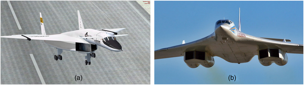
The present study addresses a symmetric channel with a longer centrebody. It may be treated as a simple model of twin intakes used in some aircraft, see Fig. 1. Both subsonic and supersonic flow conditions at the outlet are considered.

2.0 FORMULATION OF THE PROBLEM
Let profiles of the upper and lower walls of the intake be thin rectangles parallel to the x-axis:
 $${\minus}0.25\leq x\leq 0.8,\;\quad\quad 0.25\leq \left| \,y \,\right.|\leq 0.252.$$
Here and further in the paper, the Cartesian coordinates (x, y, z) are dimensional and given in metres. The centrebody profile is a pentagon with vertices
 $$x{\equals}{\minus}0.5,\,y{\equals}0\hbox{;}\,\,x{\equals}0,\,y{\equals}\!\pm0.06\hbox{;}\,\,\,x=0.8,\,y{\equals}\!\pm0.036$$
The outer boundary of the computational domain is a perimeter of the rectangle –0.75≤x≤0.8, –2≤y ≤2. On the inlet boundary, we prescribe the x-, y- and z-components of the free-stream velocity:
 $$U_{\infty} {\equals}M_{\infty} a_{\infty} \cos \alpha ,\,V_{\infty} {\equals}M_{\infty} a_{\infty} \sin \alpha ,W_{\infty} {\equals}0,\,{\rm at}\ x{\equals}{\minus}0.75,\,\left| {\,y\, \right|\leq } \right.2,$$
where M ∞>1 and α is the angle-of-attack. Also, on the inlet boundary, we impose the static pressure p ∞=105 N/m2, a turbulence level of 0.2%, and static temperature T ∞=250 K which determines the sound speed a ∞=317.02 m/s.
On the outlet boundary of the computational domain x=0.8, 0.252 ≤│y│≤2 (outside of the intake), we use the condition of supersonic flow regime.
At the outlet of the intake, x=0.8, 0.036≤│y│≤0.25 we set either
a subsonic flow regime( 18 ) (Section 1.9.3) with a given p out=3.9×10⁵ N/m2, … (4a)
or
a supersonic flow regime. …(4b)
The no-slip condition and the vanishing heat flux are prescribed on the walls and centrebody. A free-slip condition is used on the upper and lower boundaries –0.75≤x≤0.8, y=±2 of the computational domain. Initial data are either free-stream parameters or a flow field calculated for a different angle-of-attack/Mach number. The air is treated as a perfect gas whose specific heat at constant pressure is 1004.4 J/(kg K) and the ratio of specific heats is 1.4. We adopt the value of 28.96 kg/kmol for the molar mass and use the Sutherland formula for the molecular dynamic viscosity.
3.0 NUMERICAL METHOD
Solutions of the unsteady Reynolds-averaged Navier–Stokes equations were obtained with the ANSYS-15 CFX finite-volume solver of second-order accuracy. An implicit backward Euler scheme was employed for the time-accurate computations. We used a Shear Stress Transport k–ω turbulence model, which is known to reasonably predict aerodynamic flows with boundary layer separations( Reference Menter 19 ).
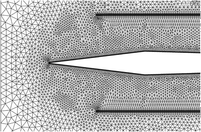
2D computational meshes were constituted by quadrangles in 37 layers on the walls and centrebody, and by triangles in the remaining region, see Fig. 2. In the channel and vicinity of the forebody, the sizes of triangles were decreased to 0.0015 m for an accurate resolution of shock waves. Moreover, mesh nodes were clustered in the boundary layer and near the throat. The non-dimensional thickness y + of the first mesh layer on the walls was less than 1. The grid sensitivity analysis was performed for flow fields with shock trains and small subsonic regions. This provides good results also for flows with large subsonic regions in which solutions are known to be smooth and less sensitive to grids. The Reynolds number based on the length of 1 m was 4.4×10⁷. The solutions obtained on uniformly refined meshes of approximately 4×10⁵, 6×10⁵, and 8×10⁵ cells showed that a discrepancy between shock wave coordinates obtained on the second and third meshes did not exceed 1%. Global time steps of 5×10⁻⁷ s and 10−6 s yielded indistinguishable solutions. For this reason, the time step of 10−6 s and mesh of 6×10⁵ cells were employed in the study of 2D transonic flow at various free-stream parameters. The root-mean-square CFL number (over mesh cells) was about 2.
Schematic of the computational mesh in the entrance region.

3D flow simulations were carried out for an intake model created by an extrusion of the 2D profile from z=0 to z=±0.3. Details of the 3D problem formulation are given in Section 5. The solver was validated by computation of several benchmark problems for transonic flow in channels and over wings( Reference Kuzmin 20 , Reference Kuzmin 21 ).
4.0 HYSTERESIS OF 2D TRANSONIC FLOWS
4.1 Symmetric flow at zero angle of attack
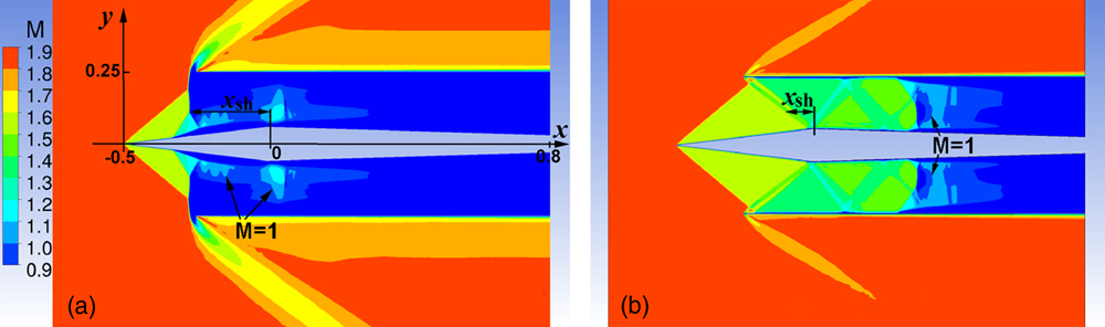
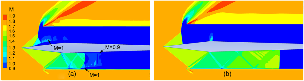
To obtain a symmetric flow, we used the uniform free stream (3) for initialization of the solution. Computations showed a convergence of the mean parameters of turbulent flow to a steady state in less than 0.2 s of physical time. At M ∞=1.75, α=0 and subsonic outlet condition (4a), the obtained solution exhibits a curved shock in front of the centrebody. When M ∞ gradually increases from 1.75 to 1.83, the shock shifts to the intake entrance and transforms into a system of oblique and nearly normal shocks, see Fig. 3(a).
(Colour online) Mach number contours in symmetric 2D flow at M ∞=1.83, vanishing angle-of-attack α=0, and subsonic outlet condition (4a). The flow field is obtained by (a) increasing M ∞ from 1.75 to 1.83; (b) decreasing M ∞ from 1.91 to 1.83.

When M ∞ further increases to 1.90, the shock system expands downstream and contacts local supersonic regions formed in the throat region (see the arrows M=1 in Fig. 3(a)). This results in formation of narrow supersonic strips/bridges over the separated boundary layer on both sides of the centrebody. An increase of M ∞ beyond 1.90 triggers a jump of the shock system downstream, a boundary-layer reattachment, and formation of a flow pattern with a train of oblique shocks. The jump is caused by the supersonic flow instability in convergent channels which was mentioned in Introduction.
The train of shocks persists when M ∞ decreases step-by-step from 1.91 to 1.83 and then to 1.77, see Fig. 3(b). However, further decrease of M ∞ to 1.76 results in an expulsion of the shocks from the channel. Therefore, in the band
 $$1.77\leq M_{\infty} \leq 1.90,$$
there exist two different symmetric flow regimes, whose realization depends on the time history of M ∞.
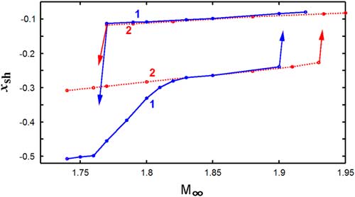
To trace the streamwise location of the bow shock generated by the upper wall of channel, we denote by x sh the abscissa of its intersection with the horizontal line y=0.125 (Fig. 3). A dependence of x sh on M ∞ for the aforementioned symmetric flows is illustrated by curve 1 in Fig. 4. The upper and lower branches of the curve correspond to flow regimes with swallowed and expelled shocks, respectively.
(Colour online) Streamwise coordinate x sh of the bow shock at y=0.125 versus M ∞ in symmetric 2D flows at α=0. Boundary condition at the intake outlet: 1 – subsonic (4a) and 2 – supersonic (4b). The upper and lower branches are obtained at decreasing M ∞ from 1.95 to 1.76 and increasing M ∞ from 1.74 to 1.93, respectively.

Curve 2 in Fig. 4 illustrates a behaviour of x sh(M ∞) in the case of the supersonic outlet condition (4b). As seen, the hysteresis width is increased. The shock coordinate x sh remains near x≈–0.3 and does not shift to the centrebody leading edge x=–0.5, y=0 when M ∞ decreases to 1.74. The latter can be explained by a suction effect produced by the supersonic region developed downstream of the throat.
4.2 Asymmetric flow at zero angle of attack
To obtain an asymmetric flow at α=0, we first solved the problem for the piecewise constant Mach number: M ∞=1.6 at y>0 and M ∞=1.8 at y≤0. The solution exhibits expelled and swallowed shock systems above and beneath the centrebody, respectively. Then a step-by-step increase of M ∞ from 1.6 to 1.8 at y>0 yields an asymmetric flow (Fig. 5(a)) for M ∞=1.8 on the entire inflow boundary.
(Colour online) Mach number contours in 2D flow with an expelled shock in the upper part of the channel and a train of shocks in the lower part at M ∞=1.8, zero angle-of-attack, and subsonic outlet condition (4a): (a) turbulent flow and (b) inviscid flow.

In the case of the subsonic outlet condition (4a), the obtained asymmetric flow persists when M ∞ varies in the band
 $$1.78\leq M_{\infty} \leq 1.90.$$
Another stable asymmetric flow in this band can be obtained by reflection of the calculated flow about the x-axis. Meanwhile if M ∞ falls below 1.78 or exceeds 1.90, then computations show abrupt transitions of the asymmetric flows to symmetric ones with expelled or swallowed shocks, respectively. It follows from (5) and (6) that, at α=0 and any M ∞ from the band (6), there exist two symmetric and two asymmetric flow regimes.
Figure 5(b) displays the inviscid asymmetric flow calculated at M ∞=1.8 by solving the Euler equations on a mesh of 7.03×10⁵ triangles. As seen, dropping the flow viscosity influences the velocity distribution, but not the existence of asymmetric regime.
In the case of the supersonic outlet condition (4b), the band (6) in which there exist asymmetric turbulent flows slightly expands:
 $$1.76\leq M_{\infty} \leq 1.93.$$
When Mach number is close to the left bound of this range, the expelled shock resides near the intake entrance, whereas in the case of the subsonic outlet condition (4a) the shock shifts upstream to the centrebody nose.
We notice that an initialization of the asymmetric solution at α=0 can also be performed by variations of α at a constant (not piecewise-constant) inflow Mach number, e.g. M ∞=1.9. This follows from a discussion of Fig. 6.
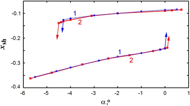
(Colour online) Streamwise coordinate x sh of the upper bow shock versus α in 2D flow at M ∞=1.9. Boundary conditions at the intake outlet: 1 – subsonic flow (4a) and 2 – supersonic flow (4b). The upper and lower branches are obtained at decreasing α from 0.7° to –4.6° and increasing α from –5.7° to 0.2°, respectively.

4.3 Hysteresis under variations of the angle of attack
A dependence of x sh on the angle-of-attack α at subsonic outlet condition (4a) and M ∞=1.9 is illustrated by curve 1 in Fig. 6. For initial state, we use a symmetric flow at M ∞=1.9, α=0 with a train of shocks similar to the one shown in Fig. 3(b). In the symmetric flow, the x sh-coordinate of the bow shocks is –0.08. A gradual decrease of α from 0 to –4.3° shifts the upper bow shock upstream, so that x sh decreases to –0.14. Further decrease of α to –4.4° triggers the upper shock expulsion from the intake and a jump of x sh from –0.14 to –0.34. Then a gradual increase of α to positive values restores the train of shocks above the centrebody. Curve 2 in Fig. 6 shows a slight expansion of the hysteresis when subsonic condition (4a) at the outlet is replaced by supersonic one (4b).
Computations demonstrated negligible distinctions between solutions obtained for the perfectly smooth surfaces of the walls/centrebody and rough ones with a sand-grain roughness of 10–5 m.
5.0 3D FLOW SIMULATIONS
A 3d intake was created by an extrusion of the profile (1), (2) from the plane z=0 to z=±0.3. For CPU savings, we assumed the flow to be symmetric about the plane z=0 and solved the problem in the semi-domain located at z>0. The sidewall of thickness 0.002 was set at 0.3≤z ≤0.302. Windward faces of the sidewall were thin oblique rectangles extending from the upper/lower wall to the centrebody leading edge. On the side boundary z=1.4 of the computational domain, we imposed the free-slip condition. A 3D mesh was constituted by 17×106 hexahedrons with refinement in the boundary layers to meet the condition y +<1.
At M ∞=1.8, α=0 and condition (4a), computations of the 3D flow using various initial conditions produced only a symmetric solution (with expelled shocks from both the upper and lower parts of the intake). Therefore, the 3D modelling did not reveal asymmetric solutions at the free-stream Mach number of 1.8 close to the left end of band (6) in which there exist asymmetric 2D flows.
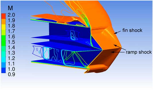
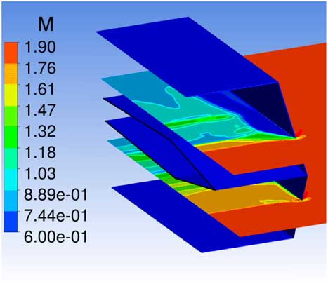
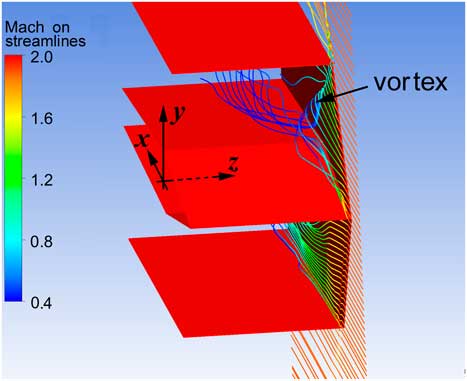
As a second case, we considered the Mach number M ∞=1.88 close to the right end of the band. Figure 7 displays shock waves in the obtained asymmetric 3D flow and contours of Mach number in the plane z=0. As seen from Figs 7 and 8, beneath the centrebody the flow is mainly supersonic; the sidewall generates just a weak perturbation in the lower part of intake. In the upper part of the intake, a nearly normal shock forms at the entrance (Fig. 7). Behind the shock the flow is subsonic, and the static pressure is abruptly increased. This produces a boundary layer separation from the sidewall (Fig. 8) and the formation of a flow structure which looks like a fin-type flow( Reference Nguyen, Behr, Reinartz, Hohn and Gülhan 22 ). The latter implies a ramp shock interaction with the fin/sidewall shock that turns, compresses, and decelerates the near-wall flow. An intricate behaviour of streamlines near the sidewall (Fig. 9) agrees with complex 3D vortex structures which are typical to the ramp shock/corner flow interactions( Reference Nguyen, Behr, Reinartz, Hohn and Gülhan 22 , Reference Knight, Panaras and Zheltovodov 23 ).
(Colour online) 3D isosurface M(x,y,z)=1.8 over the channel of half-span 0<z<0.3, and Mach number contours in the plane z=0. An asymmetric flow regime at M ∞=1.88, α=0, and condition (4a).

(Colour online) Mach number contours in sections y=±0.1 of the 3D flow shown in Fig. 7.

(Colour online) Streamlines near the sidewall in the 3D flow shown in Fig. 7.

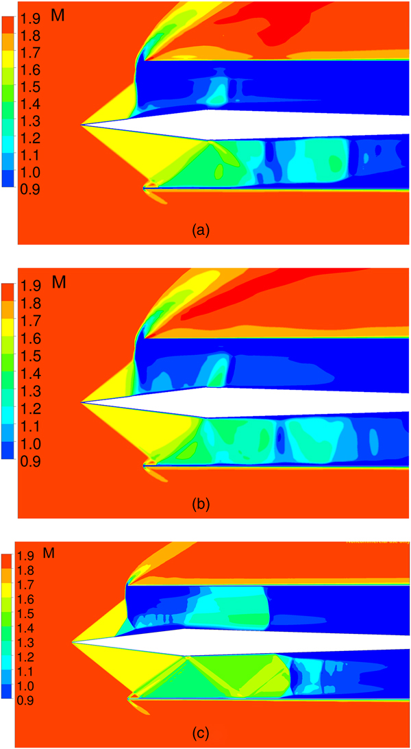
Figure 10(a) and (b) demonstrates Mach number contours in the symmetry plane z=0 and span section z=0.15 of 3D flow. Beneath the centrebody, the contours look similar to ones in the 2D flow displayed in Fig. 10(c). Above the centrebody, the supersonic region in 3D flow shrinks due to a compression produced by the boundary layer separation from the sidewall. A comparison of Figs 10(a) and (b) also shows an impact of the sidewall on flow parameters.
(Colour online) A comparison of Mach number contours: (a) and (b) – planes z=0 and z=0.15, respectively, in 3D flow shown in Fig. 7; (c) –2D flow at the same boundary conditions.

Thus, the 3D flow computations have confirmed the occurrence of asymmetric flows in the twin intake at zero angle-of-attack. In the case of half-span of 0.3, the presence of sidewall significantly influences the flow field in regimes with a nearly normal shock at the entrance. With an increasing span or Reynolds number, the effect of sidewall is expected to decrease. A detailed analysis of 3D phenomena in a twin intake will be done in a subsequent paper.
6.0 CONCLUSION
For the twin intake model, numerical simulations have demonstrated the existence of 2D flow hysteresis and non-unique regimes in considerable bands of M ∞ and α. At endpoints of the bands, small variations of free-stream parameters cause abrupt changes of shock wave positions in the intake. In particular, there are four steady flow regimes in the band (6) of M ∞ at α=0 and subsonic outlet condition (4a). This condition admits a shift of the shock system upstream to the centrebody nose at Mach numbers smaller than 1.8, whereas the supersonic condition (4b) retains the expelled shock system near the entrance. Three-dimensional phenomena turn out to be essential in the intake of half-span of 0.3 in the regimes with a strong shock formed at the entrance. The occurrence of flow hysteresis and non-uniqueness should be considered in the advanced intake design.
ACKNOWLEDGEMENTS
This research was performed using computational resources provided by the Computational Centre of St Petersburg State University (http://cc.spbu.ru). The author would like to thank Dr K. Babarykin for the help with 3D mesh generation.