Introduction
Recently, millimeter-wave bands have been used to improve the overall system performance [Reference Ullah and Tahir1, Reference Zhu, Liao, Li and Xue2, Reference Hong6, Reference Ding and Luk7]. For radar detection and the fifth generation mobile communications (5G), higher transmission quality can be achieved through improving anti-interference ability in certain specific situations. 45° linear polarized antennas facilitate advanced beamforming and beam steering techniques, allowing precise beam direction toward users, improving signal strength, and reducing interference, which have been extensively employed in practical communications [Reference Tomura, Miura, Zhang, Hirokawa and Ando3, Reference Guo, Hu and Hong4, Reference Tomura, Hirokawa, Hirano and Ando9, Reference Zhou, Lu, You, Wang and Huang23]. Moreover, they find applications in high-resolution radar systems for security and surveillance, providing detailed imagery and enhanced detection capabilities [Reference Zhong, Rashid and Zhang5, Reference Liu16].
Loading an additional layer between the feed network and the radiation part and increasing the thickness of the radiation slots are the main methods for achieving 45° linearly polarized hollow-waveguide-fed array antennas [Reference Tomura, Miura, Zhang, Hirokawa and Ando3, Reference Garcia-Marin, Masa-Campos and Sanchez-Olivares8, Reference Tomura, Hirokawa, Hirano and Ando9]. In [Reference Tomura, Miura, Zhang, Hirokawa and Ando3], the hollow-waveguide-fed array antenna is proposed with a high cross-polarization discrimination (XPD) level of 31.5 dB. However, the antenna profilehas a high thickness of 6.6 mm, which is 1.32 wavelengths at the center frequency of 60 GHz. Moreover, the impedance bandwidth of the hollow-waveguide antenna is only 6.5%. In [Reference Garcia-Marin, Masa-Campos and Sanchez-Olivares8], excessive etching occurs during the milling process of thin metal plates, when a radiation slot layer is loaded into a traditional planar stacked antenna. Due to the presence of weak parts that are prone to break and cumb in the hollow-waveguide antenna prototype, the measured impedance bandwidth is only 3.3% and the efficiency is 50%. On the basis of [Reference Tomura, Miura, Zhang, Hirokawa and Ando3], [Reference Tomura, Hirokawa, Hirano and Ando9] improves the antenna performance, achieving a bandwidth of 19.2%, an efficiency of 86.6%, and an XPD level of 30 dB in the E-band. However, the complexity of the antenna design may lead to more machining errors, thereby increasing the uncertainty of measured results.
Continuous transverse stub array antennas are used for high XPD level and efficient linearly polarized antennas [Reference Foglia10–Reference You12]. In [Reference You12], the 45° linearly polarized antenna consists of four layers: the feed network, cavity layer, radiating slots on continuous transverse stub, and 45° linear polarizer, achieving a high XPD level of 41 dB while maintaining an aperture efficiency of over 74%. But compared to [Reference Foglia10], the linear polarizer adds two additional layers, resulting in increased profile and processing complexity.
In order to solve the complex structural problems mentioned and improve the antenna performance, researchers have replaced the antennas containing a complex feed network with a substrate-integrated waveguide (SIW) antenna array. The conventional way to achieve a 45° linearly polarized antenna is to etch the 45° inclined slots on the top metal layer of the SIW [Reference Dong-yeon, Chung, Changhyun, Lee and Nam13–Reference Liu16]. In [Reference Dong-yeon, Chung, Changhyun, Lee and Nam13], the 45° linearly polarized antenna using SIW technology is achieved through two layers of standard printed circuit boards (PCBs), which, however, suffers a narrow bandwidth of only 2.88%. In [Reference Dong-yeon, Chung, Changhyun, Lee and Sangwook14], a series slot coupling antenna by alternating inductive and capacitive loading is proposed to achieve low profile and small size. Unfortunately, the narrow antenna bandwidth can only cover 2.7%, and the XPD level is 13.81 dB, which requires other technologies to optimize, such as dielectric resonator antenna and coaxial line [Reference Abdallah, Wang, Abdel-Wahab and Safavi-Naeini15, Reference Liu16]. In recent years, higher-order-mode cavities have been introduced in millimeter-wave antennas [Reference Zhao, Li, Qi and Zhu17–Reference Chen, Wu, Wong and Chen19], due to their advantages of high efficiency and compact size. In fact, above 45° linearly polarized antennas do not use higher-order mode cavities. In [Reference Chen, Wu, Wong and Chen19], a 45° linear polarized antenna is achieved by TE170-cavity-fed C-shaped patches with an efficiency of 98.9% and an XPD level of 20 dB. However, the impedance bandwidth is only 9.17%, which still needs to be improved.
This paper presents a method to achieve a 45° linear polarized 6×6 slot antenna array with high performance by means of asynmetric cross slots etched on the high-order-mode (HOM) cavity. The proposed antenna achieves broadband, high radiation efficiency, and high XDP level, while also having the advantages of simple structure and low profile. This paper is organized as follows. The 3×3 subarray design section describes the HOM cavity working principle and 3×3 subarray design. The 6×6 array design section presents the 6×6 antenna array, followed by the Conclusion section.
3×3 subarray design
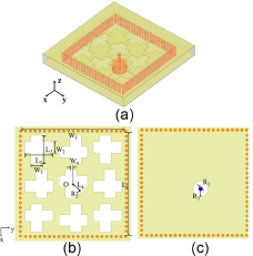
The proposed 3×3 subarray is shown in Fig. 1. The subarray consists of one substrate layer and two metallic layers. The monolayer substrate is Rogers 5880 with a thickness of 1.575 mm. The asymmetric orthogonal slots with a length, width, and offset of 3 mm, 1.2 mm, and 0.25 mm are etched at the upper metal layer. The high-order mode TE330 in the square SIW cavity is excited by the coaxial feeding. The resonant frequency of the mode is given as follows:
 \begin{equation}
f_{\text{mnp}} =\frac{c}{2\pi\sqrt{\mu\varepsilon}} \sqrt{(\frac{m\pi}{L_{\text{eff}}})^{2}+(\frac{n\pi}{W_{\text{eff}}})^{2}+(\frac{pm\pi}{h})^{2}},
\end{equation}
 \begin{equation}
\begin{aligned}
L_{\text{eff}}=L-\frac{d^{2}}{0.95p},\\
W_{\text{eff}}=W-\frac{d^{2}}{0.95p},
\end{aligned}
\end{equation}
Subarray antenna: (a) over view, (b) top view, and (c) bottom view.

where W, L, and h are the width, length, and height of the SIW cavity (SIWC) and d and p are the diameter and spacing of the SIW vias, respectively. The TE330 mode inside SIWCmeans  $\textit{m}=3$,
 $\textit{n}=3$, and
 $\textit{p}=0$. The permeability and permittivity of the substrate µ and ɛ are 1 and 2.2, respectively. The electric field is determined by (3), where E 0 and ϕ are the amplitude and phase of the waves [Reference Pozar20],
 \begin{equation}
E_{\text{Z, TE}_{330}} = E_{0}\sin\frac{3\pi x}{L_{\text{eff}}}\sin\frac{3\pi y}{W_{\text{eff}}}\cos(\omega t+\phi).
\end{equation}
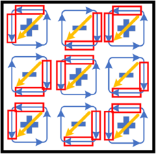
The 45° linear polarization is achieved by introducing asymmetric orthogonal slot radiation into the copper layer, which is on the top layer of the HOM cavity. To better explain the principle of the slot position by HOM cavity, the distribution diagram of electric and magnetic fields of the TE330 mode is shown in Fig. 2. The 3×3 standingwave electric peaks are evenly distributed inside the SIWC. The signs “+” and “−” represent the direction of the electric field. The closed curves indicate the magnetic vector, and its arrow direction is the vector direction. The offset transverse and the longitudinal slots with the same size are etched in each segment along the horizontal and vertical directions of the magnetic field vector. The electric field distributions at the radiation slots in this paper have the same phase. Due to the same size of the horizontal and vertical slots, the orthogonal components in the horizontal and vertical directions are of equal amplitude. A sum magnetic field vector can be formed, resulting in the radiation of 45 ° linearly polarized electromagnetic waves.
Electric field and magnetic vector of TE330 mode.

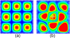
Note that the directions of the electric field in adjacent subsections are out of phase, and the directions of rotation of the magnetic field vector are opposite. Therefore, radiation in the same phase and same polarization requires etching a pair of orthogonal slots at positions with the same vector direction in each subsection. In the same way, −45° linear polarization can also be achieved in this way, and the diverse linear polarizations can be realized by designing this pair of the orthogonal slots into different size. Figure 3 illustrates the electric field distribution before and after etching the slots for the purpose of the effect of the asymmetric cross slots on the antenna radiation.
Electric field distribution at 39 GHz: (a) before etching slots and (b) after etching slots.

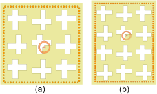
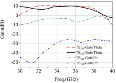
In order to achieve better antenna performance, it is necessary to determine the size of the cavity in the antenna and the mode excited within it. Figure 4 shows different antenna design and performance comparison using TE330 mode and TE340 mode. The antenna subarrays are arranged in two ways, 3×3 and 3×4. The size of the resonant cavity is calculated using (1), (2), and (3), as shown in Fig. 4. The offset of the feeding position, the size of the etching gap, and the offset value are kept consistent. From the simulation gain results of the E-plane (Phi = 45°) in Fig. 5, it can be seen that the antenna excited by TE330 mode has more advantages in XPD than the antenna excited by TE340 mode. In conclusion, for the 45° linearly polarized antenna in this paper, the cavity size has a significant impact on XPD. A square cavity can better form the 45° linearly polarized wave due to the consistent size of the metal walls, while the shape of a rectangular cavity can reduce the XPD. It is worth mentioning that when using an HOM cavity to achieve a compact design, we aim to use a single feed port to excite as many radiation slots as possible. On the other hand, we want to maintain a wide bandwidth. However, as the mode order increases, the bandwidth of the antenna decreases. This is because higher-order modes are more sensitive to the cavity size. Therefore, there is a trade-off between mode order and bandwidth.
Subarray structures: (a) 3×3 and (b) 3×4.

Radiation performance of the subarray of different resonant modes.

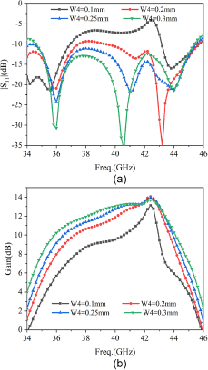
In addition, W4 is the offset dimension between the center of the transverse slot and the center of the longitudinal slot. As depicted in Fig. 6, when W4 varies between 0.1 mm, 0.2 mm, 0.25 mm, and 0.3 mm, it is evident that both the antenna matching bandwidth and the gain increase with increasing W4. To ensure the impedance bandwidth (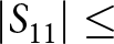 $|S_{11}|\le$ −10 dB) of the antenna, the value of W4 is chosen as 0.25mm.
The influence of the slots offset of W4 on subarray performance: (a) S-parameter and (b) gain.

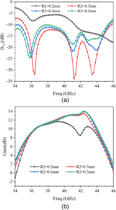
R2 is the size of concentric circle etching on the outer side of the probe in the metal layer. It can be seen from Fig. 7 that when the antenna presents an upper metal electrical contact, R2 = R1 = 0.2 mm, it can be seen that the matching situation of the antenna is much worse than that without an electrical contact. In summary, electrical contact can cause impedance matching to deteriorate, and as the R2 increases, impedance matching will deteriorate, resulting in an increase in low-frequency bandwidth. Therefore, selecting an appropriate etching size can effectively improve the working bandwidth of the antenna. So the value of R2 is chosen to be 0.4 mm.
The influence of the R2 on subarray performance: (a) S-parameter and (b) gain.

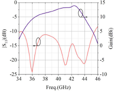
The detailed parameters are shown in Table 1 with values in millimeters. The simulated results of the proposed 45° subarray are given in Fig. 8. As shown in Fig. 8, the subarray can achieve an impedance bandwidth of 27.8% (34.4–45.53 GHz) and a 3-dB gain bandwidth of 17.1% (36.88–43.76 GHz). The maximum gain is 13.5 dBi.
The S-parameter and peak gains in the broadside direction of the subarray antenna.

Dimensions of the subarray in millimeters.

6×6 array design
Array design
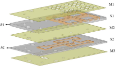
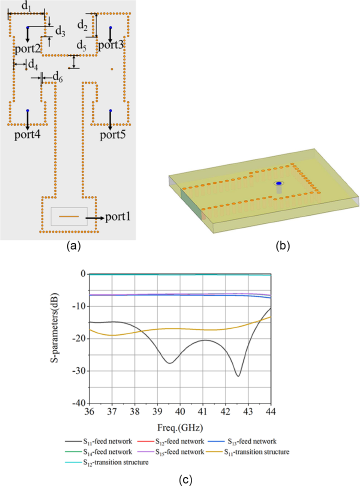
Based on the structure of the proposed subarray, an exploded view of a 6×6 antenna array is shown in Fig. 9. Two PCB layers are used for array construction. The upper layer consists of 2×2 subarrays, with a spacing of 13.2 mm between each two subarrays. Figure 10(a) shows the feed network of the proposed antenna for TE330 mode excitation. The feed network is fed by a WR-22 waveguide, and a conversion to the probe (shown in Fig. 10(b)) is used at the end to feed the subarray. The substrate of the feeding network layer is Rogers 5880 with a thickness of 0.787 mm. As shown in Fig. 10(c), the simulated −15 dB  $|S_{11}|$ bandwidths of the feed network and the transition structure cover 36–43.5 GHz. The transmission loss of the feednetwork is 0.16 dB, and the maximum difference among
 $|S_{12}|$,
 $|S_{13}|$,
 $|S_{14}|$, and
 $|S_{15}|$ is below 0.44 dB within the operation bandwidth.
3D exploded view of the proposed antenna array (  $\textit{h1}$ = 1.515 mm,
 $\textit{h2}$ = 0.787 mm).

(a) Structure of the feed network for TE330 mode. (b) Transition structure from SIW to probe. (c) Their properties in simulations ( $\textit{d1}$ = 5.5 mm,
 $\textit{d2}$ = 3.83 mm,
 $\textit{d3}$ = 1.7 mm,
 $\textit{d4}$ =
 $\textit{d5}$ = 1.8 mm,
 $\textit{d6}$ = 0.2 mm).

In the M2 layer, a larger concentric circle at the location of the probe is etched for better impedance matching. The part outside the cavity is loaded with through holes for mounting screws, in order to reduce the performance deteriation caused by the air gap between two PCBs. The feeding network design parameters and values are shown in Fig. 10.
Results and discussion
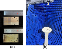
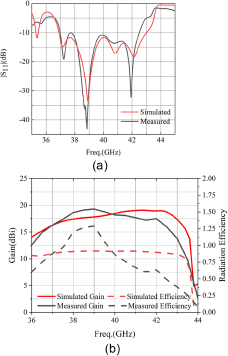
Figure 11 shows the images of the 6×6 antenna array prototype and the array in the test environment. The antenna was fabricated using standard PCB technology. The antenna array has the dimensions of 53 mm×30 mm×2.432 mm and the aperture area of 21.6 mm×21.6 mm surrounded by screw holes for assembly. In Fig. 12(a), the simulated and measured S-parameters of the 6×6 antenna array for 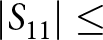 $|S_{11}|\le$ −10 dB are 15.3% (36.89–43 GHz) and 13.9% (36.98–42.52 GHz), respectively.
(a) The image of the fabricated prototype. (b) Measurement environment of the antenna.

Measured and simulated results of the antenna array. (a)  $|S_{11}|$ and (b) gain and radiation efficiency.

The antenna was measured using a spherical near-field measurement system. In Fig. 12(b), the simulated and measured peak gain is 19.06 dBi and 19.3 dBi, respectively. The simulated 3-dB gain bandwidth is 16.02% (36.85–43.31 GHz), and the measured one is 13.6% (37–42.4 GHz). The measured aperture efficiency is 88.1% at 38.5 GHz, and the average measured aperture efficiency is 66.9%. The simulated radiation efficiencies are above 86.5% within the impedance bandwidth, and the maximum radiation efficiency can reach 91.7% at 39 GHz. The average measured radiation efficiency is 75%. The discrepancies in the measured results are due to the fact that the antenna test environment is not ideal, in which the placement and the test accuracy need to be improved.
The simulated and measured radiation patterns in −90°  $ \lt $ θ
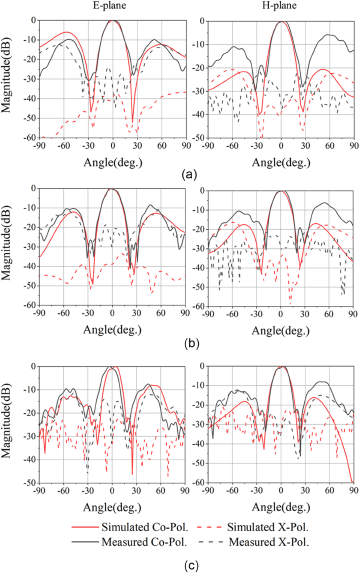
 $ \lt $ 90° are given in Fig. 13. The XPD levels in the maximum radiation direction are higher than 30 dB at 38, 40, and 42 GHz, indicating good 45° linear polarization characteristic.
Simulated and measured radiation patterns in E-plane (ϕ = 45°) and H-plane (ϕ = 135°): (a) 38 GHz, (b) 40 GHz, and (c) 42 GHz.

There are many papers that aimed at the 45° linear polarized antenna, and a comparison is made in Table 2. Compared to other SIW technology-based 45° linearly polarized antennas, the proposed antenna etching asymmetric cross slots on the top layer of HOM cavity is more dominant in terms of bandwidth and XDP level, which is better than that in [Reference Abdallah, Wang, Abdel-Wahab and Safavi-Naeini15, Reference Chen, Wu, Wong and Chen19, Reference Yu, Hong, Jiang and Zhang21] and is comparable to that in [Reference Guntupalli and Wu22]. However, [Reference Guntupalli and Wu22] has a wide impedance bandwidth at the expense of the profile. Meanwhile, [Reference Zhou, Lu, You, Wang and Huang23] and [Reference You, Lu, Skaik, Wang and Huang24] are slot array antennas fed by hollow-waveguide, which have wide impedance bandwidths and high XPD levels, but the profiles are higher than the proposed antenna. What is more, the radiation efficiency is higher than that in [Reference You, Lu, Skaik, Wang and Huang24].
Comparision with other 45° LP antennas

IBW: relative impedance bandwidth; RE: radiation efficiency; AE: aperture efficiency; XPD: cross-polarization discrimination level at θ = 0°; HW: hollow-waveguide; DR: dielectric resonator;
* : simulated results; N.A.: not apply; CS: cavity size; #:Average value within the working band
Conclusion
In this paper, a wideband and high XPD level 45° linearly polarized antenna array has been designed. Asymmetric orthogonal slots etched on the top of the high-order mode cavity contributes to low profile and wide bandwidth. Compared to the waveguide-fed antenna, the proposed antenna has the advantages in profile and radiation efficiency. In conclusion, the characteristics of the 45° linear polarized antenna show more potential in 5G communications.
Acknowledgements
This work was supported in part by the project of 2022YFF0604200 from that National Key R&D Program of China and in part by the project of 62301065 from the National Natural Science Foundation of China.
Competing interests
The author(s) declare none.

Yutong Yang received the B.E. degree in electronic information science and technology from Xidian University, Xian, China, in 2021. She is currently pursuing the M.S. degree in electronic science and technology from that Beijing University of Posts and Telecommunications. Her current research interests include characteristic modes theory and millimeter-wave antennas.

Zihang Qi received the B.E. degree in electronic and information engineering from China Three Gorges University, Yichang, China, in 2013, and the Ph.D. degree in electronic science and technology from the Beijing University of Posts and Telecommunications, Beijing, China, in 2019. He is currently an associate research fellow with the Beijing University of Posts and Telecommunications. His current research interests include orbital angular momentumantennas, millimeter-wave/THz antennas, and microwave filters.

Wenyu Zhao received the B.S. degree and Ph.D degree from the Beijing University of Posts and Telecommunications, Beijing, China, in 2018 and 2023, respectively. He is currently a postdoctoral researcher with the School of Electronic Engineering and the Beijing Key Laboratory of Work Safety Intelligent Monitoring in the Beijing University of Posts and Telecommunications. His current research interests include high-order-mode antennas, millimeter-wave antennas, and metasurface antennas.

Genqiang Kou received the B.E. degree in electronic information science and technology from Beijing University of Posts and Telecommunications, Beijing, China, in 2021. He is currently pursuing the M.S. degree in electronic science and technology from the Beijing University of Posts and Telecommunications. His current research interests include high-order-mode antennas and millimeter-wave antennas.

Xiuping Li received the B.S. degree from Shandong University in 1996, and the Ph.D. degree from the Beijing Institute of Technology in 2001. From 2001 to 2003, she joined in Positioning and Wireless Technology Center, Nanyang Technological University, where she was a research fellow and involved in the research and development of Radio Frequency Identification (RFID)system. In 2003, she was a research professor in Yonsei University, South Korea. Since 2004, she joined Beijing University of Posts and Telecommunications as an associate professor and promoted to professor in 2009. She has been selected into the New Century Excellent Talents Support Plan in National Ministry of Education, the Beijing Science and Technology Nova Support lan. She won the second prize of the Progress in Science and Technology of China Institute of Communications and the Excellent Achievements in Scientific Research of Colleges and Universities. Her research interests include millimeter-wave antennas, THz antennas, RFID systems, and Monolithic Microwave Integrated Circuit (MMIC)design.