


1 Introduction
Richtmyer–Meshkov (RM) instability (Richtmyer Reference Richtmyer1960; Meshkov Reference Meshkov1969) occurs when a shock wave accelerates an initially perturbed interface separating different fluids. RM instability is considered as a central factor in understanding the hydrodynamic processes involved in inertial confinement fusion (ICF) (Lindl et al. Reference Lindl, Landen, Edwards, Moses and Team2014), the supersonic combustion ramjet (Yang, Kubota & Zukoski Reference Yang, Kubota and Zukoski1994; Yang, Chang & Bao Reference Yang, Chang and Bao2015) and supernova explosions (Arnett et al. Reference Arnett, Bahcall, Kirshner and Woosley1989; Hammer, Janka & Müller Reference Hammer, Janka and Müller2010; Shimoda et al. Reference Shimoda, Inoue, Ohira, Yamazaki, Bamba and Vink2015). Due to the misalignment of the pressure gradient caused by the shock wave with the density gradient across the material interface, baroclinic vorticity will deposit on the interface and result in the growth of the perturbations. The growth of the shocked interface generally experiences a linear, a nonlinear and a turbulent mixing stage successively. In the ICF application (Lindl et al. Reference Lindl, Landen, Edwards, Moses and Team2014), the RM instability decreases the ignition efficiency and even leads to the failure of the ignition. To understand this instability, extensive studies on the interaction of a shock wave with a perturbed interface have been performed, and several comprehensive reviews have been presented (Zabusky Reference Zabusky1999; Brouillette Reference Brouillette2002; Ranjan, Oakley & Bonazza Reference Ranjan, Oakley and Bonazza2011; Luo et al. Reference Luo, Zhai, Si and Yang2014; Zhai et al. Reference Zhai, Zou, Wu and Luo2018).
In the previous work on the RM instability, most of the effort has been made on the evolution of a periodic single-mode or a quasi-single-mode interface. However, perturbations in reality, such as on the ICF target, are essentially random and non-periodic. In other words, unperturbed segments and perturbed segments coexist on the target surface. Therefore, it is interesting to investigate the effects of unperturbed portions on the evolution of the perturbed portions of a non-periodic and amplitude-varied interface. There are very few investigations on the evolution of a non-periodic gas interface impacted by a shock wave. Note that cylindrical and spherical bubbles, which have been extensively investigated in RM instability studies (Jacobs Reference Jacobs1992; Ranjan et al. Reference Ranjan, Oakley and Bonazza2011; Ding et al. Reference Ding, Si, Chen, Zhai, Lu and Luo2017), are non-periodic. However, they have two interfaces, and are not our concern. Shock-tube experiments on RM instability growth using an enlarged double-bump perturbation were performed by Holder et al. (Reference Holder, Smith, Barton and Youngs2003), in which the vertical interfaces were added to both sides and the middle of the double-bump perturbation. The results indicated that the evolution of the perturbed interface was influenced by the vertical portions, which indication, unfortunately, was not discussed. In the work of Jourdan & Houas (Reference Jourdan and Houas2005), the vertical interface and the bubble (spike) structure were arranged alternately on the initial interface. It was found that the vertical portions have some effects on the bubble (spike) evolution, which have not been discussed by the authors. Vandenboomgaerde et al. (Reference Vandenboomgaerde, Souffland, Mariani, Biamino, Jourdan and Houas2014) investigated the differences between the evolutions of a periodic single-mode interface and a non-periodic single-mode interface superposed with small wavelength perturbations. Two vertical segments were also added to both sides of two spike configurations to reduce the boundary wall effects. They found that the vertical segments significantly influence the movements of the spikes directly connecting to them. However, these effects were also ignored. In our previous work (Luo et al. Reference Luo, Dong, Si and Zhai2016; Zhai et al. Reference Zhai, Dong, Si and Luo2016), a chevron-shaped interface with vertical portions on both sides was created using a soap film technique. It was observed that the non-periodic feature causes different behaviours of the wave pattern and interface morphology. However, the effect of vertical portions on the evolution of the chevron-shaped interface was not clear and needs further investigation.
In this work, the effects of non-periodic portions on the evolution of a perturbed interface will be examined experimentally and theoretically in a shocked non-periodic interface. Specifically, five kinds of interfaces, including a periodic chevron-shaped interface, a chevron-shaped interface with vertical portions on both sides, an inverse-chevron-shaped interface with vertical portions on both sides, a double chevron-shaped interface with vertical portions on both sides and a double inverse-chevron-shaped interface with vertical portions on both sides are considered. The vertical segments connected to the interface generate the non-periodic feature of the interface, and, therefore, it is called the non-periodic portion of the interface. The reason for using a chevron-shaped interface mainly lies in its ease of formation using the soap film technique in our laboratory. We also note that the chevron-shaped interface can be regarded as a basic building block to form a complex interface which essentially is non-periodic and multi-modal in real circumstances. Besides, the previous work showed that an inclined interface can be treated as a single-mode perturbation with a large wavelength which determines the large scale measures such as mixing widths (McFarland et al. Reference McFarland, Reilly, Black, Greenough and Ranjan2015; Mohaghar et al. Reference Mohaghar, Carter, Musci, Reilly, McFarland and Ranjan2017). It is then expected that the present work can shed light on the effect of the non-periodic portions on the evolution of a shocked interface.
Schematics of creating a chevron-shaped interface (a) and the test section of the shock tube with the schlieren system (b).

2 Experimental method
The soap film technique, which has already been verified in terms of its feasibility and reliability in our previous work (Luo et al.
Reference Luo, Dong, Si and Zhai2016; Zhai et al.
Reference Zhai, Dong, Si and Luo2016), is adopted to create the chevron-shaped interfaces. As shown in figure 1(a), two acrylic plates (3 mm in thickness) with a depth of 20 mm are firstly manufactured, and thin pins (0.14 mm in diameter) are nailed at the inflection points. Before creating interfaces, the framework edges are wetted by a soap solution made of 78 % distilled water, 2 % sodium oleate and 20 % glycerine (numbers denote per cent by mass). Afterwards, a rectangular frame with the soap film on its surface is pulled along the interface framework, and a chevron-shaped interface can be created. Subsequently, the device is inserted into the test section and fitted tightly with optical windows on the top and bottom sides of the test section. To generate an
 $\text{air}\text{/}\text{SF}_{6}$
interface, air at the right side of the interface is removed and replaced by
 $\text{SF}_{6}$
prior to the experiment. For this purpose,
 $\text{SF}_{6}$
is injected into the test section through an ‘Inflow’ hole, and air is gradually exhausted through an ‘Outflow’ hole, as shown in figure 1(b). During this process, an appropriate inflating ratio is required to protect the formed interface. A gas concentration detector is placed at the ‘Outflow’ hole to monitor the purity of
 $\text{SF}_{6}$
at right side of the interface. In the experiment, when the concentration of oxygen is lower than 0.5 % by volume fraction, it is considered that air at the right side of the interface has been replaced by
 $\text{SF}_{6}$
completely. Then the experiment is conducted within 20 s to reduce the contamination of
 $\text{SF}_{6}$
by air. During this period, both air and
 $\text{SF}_{6}$
will penetrate through the interface and are contaminated. By measuring the velocities of incident and transmitted shock waves from the schlieren pictures, the gas components at both sides of the interface can be determined based on one-dimensional gas dynamics theory, as indicated in table 1. MF1 (MF2) denotes the mass fraction of air (
 $\text{SF}_{6}$
) at the left (right) side of the interface;
 $A=(\unicode[STIX]{x1D70C}_{2}-\unicode[STIX]{x1D70C}_{1})/(\unicode[STIX]{x1D70C}_{2}+\unicode[STIX]{x1D70C}_{1})$
is the pre-shock Atwood number with
 $\unicode[STIX]{x1D70C}_{1}$
and
 $\unicode[STIX]{x1D70C}_{2}$
being the densities of the gases at the left and right sides of the interface, respectively;
 $A^{+}$
is the post-shock Atwood number;
 $v_{s}$
is the velocity of the incident shock;
 $v_{t}$
is the velocity of the transmitted shock; and
 $\unicode[STIX]{x0394}v$
is the velocity of the post-shock flow. Before the experiments, the effect of boundary layer thickness is estimated. Because the shock Mach number is low, after the incident shock impact, the flow field behind the transmitted shock can be regarded as laminar and incompressible. As a result, the boundary layer displacement thickness (
 $\unicode[STIX]{x1D6FF}^{\ast }$
) can be approximately calculated by the expression
 $\unicode[STIX]{x1D6FF}^{\ast }=1.72\sqrt{x\unicode[STIX]{x1D707}/\unicode[STIX]{x1D70C}\unicode[STIX]{x0394}v}$
where
 $x$
(
 $=100~\text{mm}$
measured from experiment) is the maximum distance that the interface moves when image recording ends, and
 $\unicode[STIX]{x1D707}$
is the viscosity coefficient of the gas. To simplify the calculation, the gas parameters of pure air as ambient gas and pure
 $\text{SF}_{6}$
as test gas at a temperature of 293 K are adopted.
 $\unicode[STIX]{x1D707}$
is
 $1.83\times 10^{-5}~\text{Pa}~\text{s}$
(
 $1.60\times 10^{-5}~\text{Pa}~\text{s}$
) for air (
 $\text{SF}_{6}$
) and
 $\unicode[STIX]{x1D70C}$
is
 $1.204~\text{kg}~\text{m}^{-3}$
(
 $6.143~\text{kg}~\text{m}^{-3}$
) for air (
 $\text{SF}_{6}$
). According to the expression,
 $\unicode[STIX]{x1D6FF}^{\ast }$
is calculated as approximately equal to 0.25 mm for ambient gas and 0.1 mm for test gas based on
 $\unicode[STIX]{x0394}v=70~\text{m}~~\text{s}^{-1}$
when the experiment ends, which values are much smaller than the inner height of the acrylic plates (20 mm). Therefore, the effect of the boundary layer on interface evolution is limited and can be neglected.
Experimental initial parameters for all cases.
 $h_{0}$
is the initial mixing width, and
 $\unicode[STIX]{x1D706}$
is the wavelength of perturbed portion. MF1 (MF2) means the mass fraction of air (
 $\text{SF}_{6}$
) at the left (right) side of the interface;
 $A=(\unicode[STIX]{x1D70C}_{2}-\unicode[STIX]{x1D70C}_{1})/(\unicode[STIX]{x1D70C}_{2}+\unicode[STIX]{x1D70C}_{1})$
is the pre-shock Atwood number with
 $\unicode[STIX]{x1D70C}_{1}$
and
 $\unicode[STIX]{x1D70C}_{2}$
being the densities of the gases on the left and right sides of the interface, respectively;
 $A^{+}$
is post-shock Atwood number;
 $v_{s}$
is the velocity of the incident shock;
 $v_{t}$
is the velocity of the transmitted shock; and
 $\unicode[STIX]{x0394}v$
is the velocity of the post-shock flow.

The experiments are performed in a horizontal shock tube which consists of a 1.7 m long driver section, 2.0 m long driven section and a 0.6 m long test section with a cross-sectional area of
 $120~\text{mm}\times 20~\text{mm}$
. In this work, five kinds of chevron-shaped interfaces, as sketched in figure 2(a–e), are considered. For each case, several experiments are performed, by changing the Atwood number or initial amplitude–wavelength ratio, in order to investigate the effects of the initial conditions on the interface development. The variation of Atwood number in this work is achieved by adjusting the mixing ratio of air and
 $\text{SF}_{6}$
, rather than using different gases. The initial parameters for all cases are given in table 1. For all cases, the initial perturbed amplitude (
 $a_{0}$
) is defined as half of the initial mixing width (
 $h_{0}$
), and the wavelength of the perturbed interface and the length of the vertical portion are
 $\unicode[STIX]{x1D706}$
and
 $L$
, respectively. The initial amplitude–wavelength ratio
 $a_{0}/\unicode[STIX]{x1D706}$
is smaller than 0.1 for all cases, satisfying the small perturbation hypothesis. After the shock impact, the post-shock flow field is illuminated by a DC regulated light source (CEL-HXF300, the maximum power output is 249 W) and captured by schlieren photography combined with a high-speed video camera (FASTCAM SA5, Photron Limited). The frame rate of the camera is 50 000 f.p.s. (corresponding to a time interval of
 $20~\unicode[STIX]{x03BC}\text{s}$
), and the exposure time is
 $1~\unicode[STIX]{x03BC}\text{s}$
for all cases. The pixel resolution is approximately
 $0.3~\text{mm}~\text{pixel}^{-1}$
. The incident shock Mach number is
 $1.20\pm 0.01$
from all the measurements, which indicates that the shock tube facility has a very good repeatability. The room temperature
 $T_{0}$
is approximately 293 K and the initial pressure
 $p_{0}$
is 101 325 Pa.
Schematics of initial interface configurations. For convenience, we call these five kinds of interfaces the periodic chevron-shaped interface (PCS), chevron-shaped interface with vertical portions on both sides (CS), inverse-chevron-shaped interface with vertical portions on both sides (ICS), double chevron-shaped interface with vertical portions on both sides (DCS) and the double inverse-chevron-shaped interface with vertical portions on both sides (DICS), respectively.

3 Results and discussion
3.1 Periodic chevron-shaped interface
Figure 3 shows the shock propagation and the interface deformation before and after a periodic chevron-shaped interface (PCS-1) is accelerated by a planar shock wave. The initial time is defined as the moment the incident shock wave (IS) passes through the interface centre. When the IS impacts the interface, a transmitted shock wave (TS) and a reflected shock wave (RS) with a chevron shape are generated. The interface acquires energy from the shock wave and begins to move. As time elapses, the perturbation amplitudes on the TS and RS gradually decrease while the amplitude on the compressed interface grows because of the baroclinic vorticity induction. The mixing width of the interface increases, accompanied by the appearance of bubble and spike structures. From the schlieren pictures, one can find that the pins used to restrain the interface only affect the spike and bubble heads a little, and have limited effects on the whole interface morphologies, especially on the interface amplitude (Vandenboomgaerde et al. Reference Vandenboomgaerde, Rouzier, Souffland, Biamino, Jourdan, Houas and Mariani2018) and circulation deposited (Wang, Si & Luo Reference Wang, Si and Luo2013).
Schlieren pictures of the periodic chevron-shaped interface (PCS-1) accelerated by a planar shock wave. Numbers denote the time in
 $\unicode[STIX]{x03BC}\text{s}$
, and similarly hereinafter.

Comparison of initial chevron-shaped interface with the superimposed interface by the five lowest orders of harmonics.

For a pure chevron-shaped interface (corresponding to one period in the periodic chevron-shaped interface), the previous work (Mikaelian Reference Mikaelian2005; Luo et al. Reference Luo, Dong, Si and Zhai2016) showed that the interface can be expressed in the form of a Fourier expansion as
 $$\begin{eqnarray}y(x)=a_{0}[-0.811\cos (kx)-0.090\cos (3kx)-0.032\cos (5kx)-\cdots \,],\end{eqnarray}$$
where
 $y$
and
 $x$
represent coordinates of the interface, and
 $k=2\unicode[STIX]{x03C0}/\unicode[STIX]{x1D706}$
is the wavenumber. The components and their superposition are given in figure 4. The results indicate that a pure chevron-shaped interface contains
 ${\sim}81\,\%$
fundamental mode and
 ${\sim}19\,\%$
high-order harmonics. From previous work (Luo et al.
Reference Luo, Dong, Si and Zhai2016), one can conclude that the fundamental mode almost determines the mixing width of the interface.
We first consider the linear stage. For an interface with a small amplitude, Richtmyer (Reference Richtmyer1960) firstly analysed the linear growth rate of a single-mode perturbation provided that the flow field is incompressible, and proposed an impulsive model,
 $$\begin{eqnarray}v_{0}=\frac{\text{d}a}{\text{d}t}=k\unicode[STIX]{x0394}vA^{+}a_{0}^{+},\end{eqnarray}$$
in which
 $a_{0}^{+}=(1-\unicode[STIX]{x0394}v/v_{s})a_{0}$
is the post-shock amplitude. The impulsive model has been widely verified to predict the linear growth rate of interfaces with small amplitudes. In this work, the linear growth rates of the amplitude in the experiments for the three periodic chevron-shaped interfaces (PCS-1, PCS-2 and PCS-3) are measured to be
 $9.97\pm 1.06$
,
 $7.89\pm 0.8$
and
 $15.4\pm 1.28~\text{m}~\text{s}^{-1}$
, respectively, and the corresponding theoretical values predicted by the impulsive model are 9.89, 7.16 and
 $14.54~\text{m}~\text{s}^{-1}$
, respectively. The good agreement between the theoretical predictions and the experimental results shows that the fundamental mode indeed determines the interface evolution in the linear stage.
In the nonlinear phase, there are several models available to predict the width growth of a single-mode interface. It is interesting to evaluate these models using the periodic chevron-shaped interface which is essentially a multi-modal one. Mikaelian (Reference Mikaelian1998, Reference Mikaelian2003) constructed a simple nonlinear model (Mik model) to bridge the gap between the linear stage and the late-time nonlinear stage. As the dimensionless amplitude,
 $a_{0}^{+}k$
, reaches
 $1/3$
, the formula smoothly shifts to a logarithmic growth. Dimonte & Ramaprabhu (Reference Dimonte and Ramaprabhu2010) proposed a nonlinear model (DR model) to deal with the applications where
 $A^{+}$
and
 $ka_{0}$
are large. Some coefficients and the initial velocity were fitted to match numerical simulations and some experiments. Zhang & Guo (Reference Zhang and Guo2016) recently also proposed a nonlinear model (ZG model), considering the universal curve of the spike and bubble structures at finite density ratios. Combining the asymptotic solution of the compressible flow equations (Zhang & Sohn Reference Zhang and Sohn1996) with a potential flow model (Alon et al.
Reference Alon, Hecht, Ofer and Shvarts1995), Sadot et al. (Reference Sadot, Erez, Alon, Oron, Levin, Erez, Ben-Dor and Shvarts1998) proposed a nonlinear model (Sad model) to predict the growth rate of the bubble or spike based on buoyancy–drag considerations and the initial linear growth rate
 $v_{0}$
,
 $$\begin{eqnarray}\frac{\text{d}a_{b/s}}{\text{d}t}=\frac{(1+\unicode[STIX]{x1D70F})v_{0}}{1+(1\pm A^{+})\unicode[STIX]{x1D70F}+E_{b/s}\unicode[STIX]{x1D70F}^{2}},\end{eqnarray}$$
where
 $\unicode[STIX]{x1D70F}=kv_{0}t$
. In the denominator,
 $+A^{+}$
and
 $-A^{+}$
are adopted when predicting the growth of bubble and spike, respectively.
 $E_{b/s}$
is
 $3(1\pm A^{+})/2(1+A^{+})$
when
 $A^{+}\geqslant 0.5$
, and
 $(1\pm A^{+})/(1+A^{+})$
when
 $A^{+}\rightarrow 0$
. This model agrees with the vortex model when
 $A^{+}\rightarrow 0$
(
 $\text{d}a_{b}/\text{d}t\rightarrow 1/(kt)$
) (Jacobs & Krivets Reference Jacobs and Krivets2005) and Layzer’s asymptotic result (Layzer Reference Layzer1955; Hecht, Alon & Shvarts Reference Hecht, Alon and Shvarts1994) when
 $A^{+}\rightarrow 1$
(
 $\text{d}a_{b}/\text{d}t\rightarrow 3/(2kt)$
) at late times provided that some coefficients are adjusted to fit the growth rates obtained in some experiments and numerical simulations.
Comparisons of dimensionless mixing width
 $h$
(a),
 $a_{b}$
and
 $a_{s}$
(b) of the periodic chevron-shaped interfaces between experimental results and theoretical predictions.

Comparisons of the dimensionless mixing width (
 $h$
), the dimensionless spike width (
 $a_{s}$
) and the bubble width (
 $a_{b}$
) of the periodic chevron-shaped interface of four nonlinear models are shown in figure 5. In experiments, the interface boundaries are measured by the central position of the material layers, and the error bars result from the thickness of the material layer in the schlieren images. To measure the amplitudes of the spike and the bubble, it is considered that the balanced position, which is the centre of the periodic chevron-shaped interface, as presented in figure 4 before shock impact, moves with a velocity of
 $\unicode[STIX]{x0394}v$
after shock impact, and then the position differences between the balanced position and the tips of the bubble and spike are treated as the amplitudes of the bubble and spike, respectively. For the mixing width
 $h$
, one can observe that the Sad model well predicts the experimental results, and the DR model slightly underestimates the experimental growth after approximately a dimensionless time of 0.7, while both the Mik model and the ZG model underestimate the experimental growth. For the spike width
 $a_{s}$
, these four nonlinear models give similar predictions for the mixing width. However, all the models give a reasonable prediction of the bubble evolution. Therefore, the failure of the models in predicting the mixing width is mainly ascribed to the poor estimation of the spike evolution because the spike is more unstable than the bubble (Mikaelian Reference Mikaelian2008; Vandenboomgaerde et al.
Reference Vandenboomgaerde, Souffland, Mariani, Biamino, Jourdan and Houas2014; Zhang & Guo Reference Zhang and Guo2016). The periodic chevron-shaped interface differs from the single-mode interface mainly in two ways: it has tips and it is a multi-modal interface. In general, the tips and the multi-modal feature of an interface facilitate perturbation growth, because all the higher-order harmonic modes have the same sign as the fundamental mode, and therefore promote the growth rate of the interface. As a result, we claim that the tips and multi-modal feature of the chevron-shaped interface favour the Sad model, which may partially consider the high-order harmonic modes and gives the highest growth rate among these nonlinear models (Jacobs & Krivets Reference Jacobs and Krivets2005).
Comparisons of dimensionless mixing width
 $h$
of the periodic chevron-shaped interface between the present experimental results and the previous numerical result (McFarland, Greenough & Ranjan Reference McFarland, Greenough and Ranjan2011).

In the previous work (McFarland et al.
Reference McFarland, Greenough and Ranjan2011), a periodic chevron-shaped interface was thoroughly investigated numerically. For comparison with our experimental work, the case of Air M15A60 in that work is adopted here because in this case the initial conditions, such as the shock Mach number and vertex angle, are similar to the present work. Based on the scaling laws in the work of McFarland et al. (Reference McFarland, Greenough and Ranjan2011), the present results are re-obtained, and the predictions from some models are also presented, as shown in figure 6 in which
 $t^{\ast }$
is the time required for the shock wave to traverse the inclined interface amplitude
 $h$
. One can find that the Sad model fails to predict the growth of the interface in the previous work, which is similar to the conclusion obtained by McFarland et al. (Reference McFarland, Greenough and Ranjan2011). Note that the small perturbation hypothesis in the Air M15A60 case in that work was not satisfied because the amplitude–wavelength ratio was larger than 0.1. However, the linear velocity
 $v_{0}$
obtained by the impulsive model was adopted to normalize the time, and, therefore, the Sad model was not applicable. According to our previous work (Luo et al.
Reference Luo, Dong, Si and Zhai2016), for a high initial amplitude, a reduction factor (
 $R=0.75$
) is adopted here to re-calculate the linear velocity
 $v_{0}$
. For the new linear velocity, the dimensionless time is re-calculated, and the interface growth is also given for comparison, as indicated in figure 6. One can find that the Sad model can also provide a good prediction for the interface growth, especially from early to intermediate stages. Because the comparisons verify the applicability of the Sad model for predicting the evolution of the periodic chevron-shaped interface, we will choose the Sad model to predict the non-periodic interface evolution in the following discussion.
3.2 Non-periodic chevron-shaped interfaces
Evolutions of a chevron-shaped interface (CS-1) and an inverse-chevron-shaped interface (ICS-1) are shown in figures 7 and 8, respectively. Note that both interfaces have vertical portions on both sides. In the chevron-shaped interface, generally, the shape of the deformed interface is similar to the spike component in the periodic chevron-shaped interface. However, influenced by the vertical portions on both sides, the bubble component is stretched and becomes flat, which is different from the bubble evolution in the periodic chevron-shaped interface. In the inverse-chevron-shaped interface, the shape of the deformed interface is similar to the bubble component in the periodic chevron-shaped interface as a whole. Because of the existence of vertical portions, vortex pairs occur at the tips of the spike component, and as the interface moves forward, the vortex pairs evolve toward each other.
Schlieren pictures of the chevron-shaped interface (CS-1) impacted by a planar shock wave.

Schlieren pictures of the inverse-chevron-shaped interface (ICS-1) impacted by a planar shock wave.

Time variations of the dimensionless mixing width
 $h$
in experiments, as defined in figures 7 and 8 for the chevron-shaped and inverse chevron-shaped interfaces, are shown in figures 9(a) and 9(b), respectively. The predictions of
 $h$
by the Sad model are also given in the figures. It is observed that the Sad model slightly underestimates the mixing width in the chevron-shaped interface, but it overestimates the mixing width in the inverse chevron-shaped interface. It can be seen by comparing with the periodic chevron-shaped interface that the evolution of the perturbed interface is influenced by the vertical portions on both sides.
Comparisons of dimensionless mixing width
 $h$
of the chevron-shaped interface (a) and the inverse-chevron-shaped interface (b) between experimental results and predictions.

The superimposed interface by five lowest orders of harmonics for the chevron-shaped interface.

To determine the effects of the non-periodic portions on the evolution of the chevron-shaped part, the whole initial interface, including vertical portions (i.e. the new wavelength
 $\unicode[STIX]{x1D706}^{\prime }$
is 120 mm, which is a combination of
 $\unicode[STIX]{x1D706}$
with double the length of vertical portions, and the new wavenumber
 $k^{\prime }=2\unicode[STIX]{x03C0}/\unicode[STIX]{x1D706}^{\prime }$
) is expressed in the form of a Fourier expansion,
 $$\begin{eqnarray}y(x)=a_{0}[-0.604\cos (k^{\prime }x)+0.454\cos (2k^{\prime }x)-0.270\cos (3k^{\prime }x)+0.115\cos (4k^{\prime }x)-\cdots \,].\end{eqnarray}$$
For the chevron-shaped and inverse-chevron-shaped interfaces, the form of
 $y(x)$
is the same but the signs of each item are opposite because of the opposite phase. As we can see, the even-order items exist in the initial interface, which differs from the single-mode interface where the second-order term only occurs as the interface evolves (Mikaelian Reference Mikaelian1994). The second-order term provides a constant acceleration for the bubble and the spike, which move in the opposite directions, and, therefore, is the lowest order for asymmetry of the bubble and spike evolutions (Velikovich, Herrmann & Abarzhi Reference Velikovich, Herrmann and Abarzhi2014). For a single-mode interface or a periodic chevron-shaped interface, the balanced position of the initial interface is the centre of the spike and the bubble. For a chevron-shaped interface with vertical portions, the initial even-order terms change the balanced position between the spike and the bubble, as shown in figure 10. Influenced by the vertical portions, the new balanced position (
 $y=0$
) is not the centre of the chevron-shaped interface any more, but is much closer to the non-periodic (vertical) portions. Therefore, the proportion of the spike component is larger than that of the bubble component in the chevron-shaped interface, and vice versa in the inverse-chevron-shaped interface. Through substituting
 $xk^{\prime }=\unicode[STIX]{x03C0}$
and
 $xk^{\prime }=2\unicode[STIX]{x03C0}L/(2L+\unicode[STIX]{x1D706})$
into (3.4), one can find that the proportions of the initial width of the spike (
 $a_{0s}$
) and the bubble (
 $a_{0b}$
) are respectively 0.82 and 0.18 in the chevron-shaped interface, i.e.
 $a_{0s}/h_{0}=0.82$
and
 $a_{0b}/h_{0}=0.18$
. As the length of the vertical portions (
 $L$
) varies compared with the wavelength of the chevron-shaped interface (
 $\unicode[STIX]{x1D706}$
), the balanced position, i.e.
 $a_{0s}/a_{0b}$
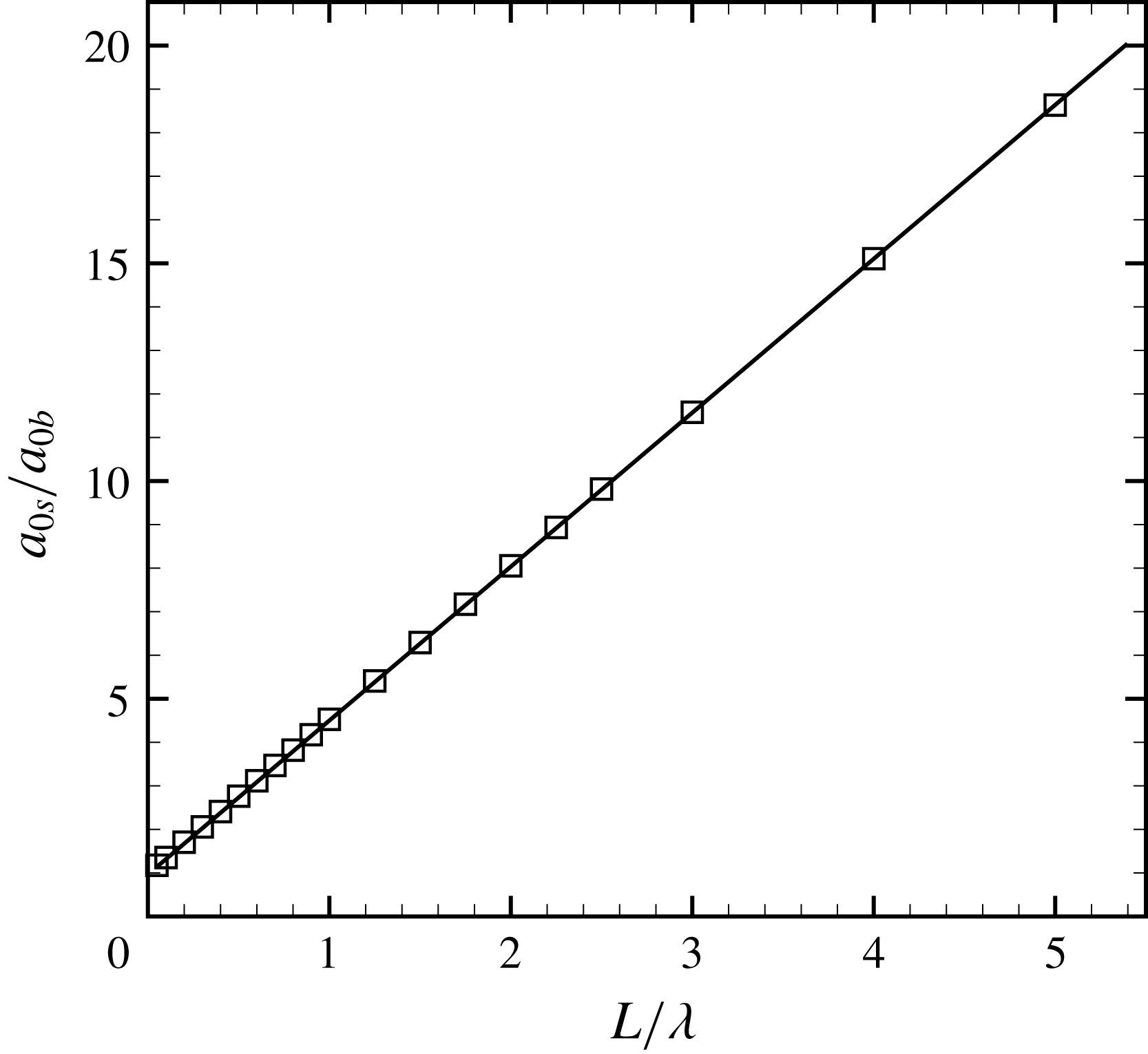
, will change accordingly. The relationship of
 $a_{0s}/a_{0b}$
with
 $L/\unicode[STIX]{x1D706}$
in the chevron-shaped interface is given in figure 11. When
 $L$
is 0, i.e. the initial chevron-shaped interface is periodic,
 $a_{0s}$
and
 $a_{0b}$
are the same. As the value of
 $L/\unicode[STIX]{x1D706}$
increases, the spike component dominates the interfacial evolution in the chevron-shaped interface while the bubble component dominates the interfacial evolution in the inverse-chevron-shaped interface. When
 $\unicode[STIX]{x1D706}$
is infinitesimal compared to
 $L$
, the chevron-shaped interface can be regarded as a pure spike structure and the inverse-chevron-shaped interface as a pure bubble structure. Through linear fitting, the relationship of
 $a_{0s}/a_{0b}$
with
 $L/\unicode[STIX]{x1D706}$
can be represented as
 $$\begin{eqnarray}\frac{a_{0s}}{a_{0b}}=3.53\frac{L}{\unicode[STIX]{x1D706}}+1.\end{eqnarray}$$
From this equation, one can easily calculate the initial proportions of the spike and the bubble compared with the initial mixing width of the perturbation on the interface, and then the amplitude growth rates of the spike and the bubble can be theoretically analysed.
Variations of the initial proportions of the spike and bubble compared with the ratio of the vertical portion length with wavelength of perturbed interface for the chevron-shaped interface.
According to (3.5), the Sad model can be modified to predict the growth rates of spike (
 $a_{s}$
) and bubble (
 $a_{b}$
) for the chevron-shaped interface and inverse-chevron-shaped interface. After substituting
 $a_{0b/0s}/h_{0}$
by the symbol
 $\unicode[STIX]{x1D719}$
for simplicity, the modified Sad model (MSad) is written as
 $$\begin{eqnarray}\frac{\text{d}a_{b/s}}{\text{d}t}=\frac{(1+2\unicode[STIX]{x1D70F}\unicode[STIX]{x1D719})2v_{0}\unicode[STIX]{x1D719}}{1+(1\pm A^{+})2\unicode[STIX]{x1D70F}\unicode[STIX]{x1D719}+E_{b}/s(2\unicode[STIX]{x1D70F}\unicode[STIX]{x1D719})^{2}}.\end{eqnarray}$$
Equation (3.6) has the same form as (3.3) if
 $\unicode[STIX]{x1D719}=0.5$
for a periodic initial interface. Time variations of the dimensionless
 $a_{s}$
and
 $a_{b}$
for the chevron-shaped and inverse-chevron-shaped interfaces are shown in figures 12(a) and 12(b), respectively, from the experiments together with the predictions from the Sad and MSad models. For the chevron-shaped interface, the Sad model underestimates the width growth of
 $a_{s}$
and overestimates the width growth of
 $a_{b}$
because
 $a_{0s}$
is larger than
 $a_{0b}$
. Instead, for the inverse-chevron-shaped interface, the Sad model overestimates the width growth of
 $a_{s}$
and underestimates the width growth of
 $a_{b}$
because
 $a_{0s}$
is smaller than
 $a_{0b}$
. By considering the initial proportions of spike and bubble, the MSad model can give reasonable predictions of
 $a_{s}$
and
 $a_{b}$
for both the chevron-shaped and inverse-chevron-shaped interfaces. Consequently, the predictions of the mixing width (
 $h$
) from the MSad model also agree well with experimental results in both the chevron-shaped and inverse-chevron-shaped interfaces, as illustrated in figure 9(a,b).
Comparisons of dimensionless widths
 $a_{s}$
and
 $a_{b}$
of the chevron-shaped interface (a) and the inverse-chevron-shaped interface (b) between experimental results and predictions.

Schlieren pictures of the interface impacted by a planar shock wave in the double chevron-shaped interface (DCS-1).

Figure 13 shows the evolution of the double chevron-shaped interface (DCS-1) accelerated by a planar shock wave. The evolution of the bubble at the central axis in the double chevron-shaped interface is similar to that in the periodic chevron-shaped interface. Note that the central bubble moves with a different velocity from the side bubble connected by non-periodic portions. The two spikes skew toward each other as the interface moves forward, which is not observed in the periodic chevron-shaped interface and chevron-shaped interface. This phenomenon is ascribed to the competition between bubbles with different wavelengths, which was observed before (Sadot et al.
Reference Sadot, Erez, Alon, Oron, Levin, Erez, Ben-Dor and Shvarts1998). The interface mixing widths regarding the central and side bubbles, as indicated by
 $h_{1}$
and
 $h_{2}$
respectively in figure 13, are shown in figure 14(a). It is indicated that the Sad model works well for the former while the MSad model works well for the latter. These results once again verify that the evolution of a chevron-shaped interface will be influenced by the non-periodic portions on both sides. Further, comparisons of
 $a_{s}$
and
 $a_{b}$
between the experimental results and predictions are shown in figure 14(b). Because the central bubble is not directly connected to the non-periodic portions, the evolution of the central bubble will be predicted well by the Sad model. However, the side bubble evolution is affected by the non-periodic portion, and the Sad model becomes invalid. According to the Fourier expansion, we find
 $a_{0s}/h_{0}=0.735$
and
 $a_{0b}/h_{0}=0.265$
, and the MSad model can effectively predict the side bubble growth using these relations. For the spikes, because the tips are not directly connected to the non-periodic portions, the spike width will not be affected by the non-periodic portions at the early stage, and the Sad model can work well, as indicated in figure 14(b) before dimensionless time of 1.5 (
 $955~\unicode[STIX]{x03BC}\text{s}$
). After that, the non-periodic portions will still exert their effects on the connected interface, resulting in the different velocities of the interfaces at both sides of the tip. As a result, the prediction of the Sad model deviates from the experimental result at late stages.
Comparisons of dimensionless mixing width
 $h$
(a),
 $a_{b}$
and
 $a_{s}$
(b) of the interface in the double chevron-shaped interface (DCS-1) between experimental results and predictions.

As shown in figure 15, the evolution of the spike at the central axis in the double inverse-chevron-shaped interface (DICS-1) is similar to that in both of the periodic chevron-shaped interface and the chevron-shaped interface. It can be found that the central spike moves with a different velocity from the side spike connected by the non-periodic portions. The two side spikes obviously roll up, which is similar to the inverse-chevron-shaped interface. The interface mixing widths regarding the central and side spikes, as indicated by
 $h_{1}$
and
 $h_{2}$
respectively in figure 15, are shown in figure 16(a). It is indicated that the Sad model works well for the former while the MSad model works well for the latter, which is consistent with the observations in the double chevron-shaped interface. Comparisons of
 $a_{s}$
and
 $a_{b}$
between the experimental results and predictions are shown in figure 16(b). Because the central spike is not directly connected to the non-periodic portions, the evolution of the central spike is well predicted by the Sad model. However, the Sad model becomes invalid for the side spike evolution which is affected by the non-periodic portions. The MSad model can effectively predict the side spike growth using the relations
 $a_{0b}/h_{0}=0.735$
and
 $a_{0s}/h_{0}=0.265$
obtained from the Fourier expansion. For the bubbles, as illustrated in figure 14(b), the Sad model works well because the tips are not directly connected to the non-periodic portions and the bubble width will not be affected by the non-periodic portions.
Schlieren pictures of the double inverse-chevron-shaped interface (DICS-1) impacted by a planar shock wave.

Comparisons of dimensionless mixing width
 $h$
(a),
 $a_{b}$
and
 $a_{s}$
(b) of the double inverse-chevron-shaped interface between experimental results and predictions.

From the analysis above, we can conclude that the Sad model can predict the evolution of the bubble or spike well when it separates from the non-periodic portions, and the MSad model can correctly describe the growth behaviours of the bubble or spike when it is connected by the non-periodic portions because the MSad model considers the shift of the balanced position caused by the non-periodic portions. The variation of the balanced position changes the proportions of the spike and bubble, i.e. the initial amplitudes of the spike and bubble, and then the growth rate of perturbation amplitude, while the growth tendency will not be affected. Note that in the Sad model, the amplitude growth rate in the nonlinear phase is in proportion to the initial linear velocity
 $v_{0}$
which is directly proportional to the initial amplitude. Using the initial proportions of the spike and bubble, the dimensionless growths for all cases are re-calculated. For example, for the chevron-shaped interface, because
 $a_{0s}/h_{0}=0.82$
and
 $a_{0h}/h_{0}=0.18$
, compared with the periodic chevron-shaped interface, the growth of the spike in the chevron-shaped interface will be multiplied by a factor of
 $0.82/0.5=1.64$
while the growth of the bubble in the chevron-shaped interface will be multiplied by a factor of
 $0.18/0.5=0.36$
. The new dimensionless growths of the spike and the bubble for all cases are shown in figure 17, and all curves collapse well. Note that only side bubbles and side spikes in the double chevron-shaped interface and double inverse-chevron-shaped interface are considered in figure 17. Therefore, the Sad model can give fairly good predictions for the evolution of bubble and spike if the initial proportions of the spike and bubble are considered.
Dimensionless
 $a_{b}$
and
 $a_{s}$
of the five interfaces using the corrected balanced positions. The Sad model adopts the corrected balanced positions.

4 Conclusions
In this work, evolutions of chevron-shaped
 $\text{air}\text{/}\text{SF}_{6}$
gaseous interfaces accelerated by planar shock waves are investigated, focusing on the effects of the vertical portions on the evolution of the non-periodic interface. In the experiments, five kinds of discontinuous chevron-shaped interfaces, i.e. a periodic chevron-shaped interface and four kinds of non-periodic chevron-shaped interfaces with vertical portions on both sides, are created using the soap film technique, and the post-shock flows are captured by schlieren photography combined with a high-speed video camera.
The evolution of a periodic chevron-shaped interface is first considered to evaluate several typical nonlinear models for the mixing width growth and the amplitudes of the spike and bubble. Study of the evolution of the shocked chevron-shaped interface is important to understand the behaviour of a very complex interface subjected to a shock because the chevron-shaped interface is a typical complex interface. Specifically, the chevron-shaped interface differs from the single-mode interface mainly in two ways, i.e. it has tips and it is a multi-modal interface. It is found that the model proposed by Sadot et al. (Reference Sadot, Erez, Alon, Oron, Levin, Erez, Ben-Dor and Shvarts1998) can give reasonable predictions for both the spike and the bubble, while other models only predict the bubble growth well but fail to predict the spike growth because the bubble is more stable than the spike. We claim that the tips and multi-modal feature of the periodic chevron-shaped interface facilitate the growth rate, because all the higher-order harmonic modes have the same sign as the fundamental mode, and, therefore, promote the growth rate of interface, which favours the Sad model (Sadot et al. Reference Sadot, Erez, Alon, Oron, Levin, Erez, Ben-Dor and Shvarts1998).
The evolutions of four kinds of non-periodic chevron-shaped interface with vertical portions on both sides are then investigated. The results show that the nonlinear model, which is applicable to the periodic chevron-shaped interface, becomes invalid for its non-periodic counterpart. For a chevron-shaped interface with vertical portions on both sides, the Fourier expansion of the interface profile shows that the existence of the non-periodic portions results in the occurrence of even-order items on the initial interface, and the balanced position, which is the centre of the interface for periodic interfaces, will vary as the length of the vertical portions changes compared with the wavelength of the perturbed interface. The variations of the balanced position can be regarded as variations of the initial proportions of the spike and bubble. By considering the initial proportions of the spike and bubble, the Sad model is modified such that it can predict the width growth for the non-periodic interface well. Therefore, the behaviour of a shocked non-periodic interface can be correctly predicted by including the contribution from the spike (bubble) portion.
In conclusion, the non-periodic interface normally contains both the bubble and spike structures and the ratio of bubble structure to spike structure has a significant effect on the RM instability. The influence of the vertical portions on the non-periodic interface evolution can be ascribed to the change of the balanced position of the interface such that existing nonlinear model for periodic interface can be applied to a non-periodic one by taking this change into account. This can be realized by using spectrum analysis on the initial shape of the interface such that its bubble structure and spike structure can be separated. However, this should be further verified by studying other non-periodic interfaces with different shapes, such as a non-periodic single-mode interface, which will be performed in the near future.
Acknowledgements
This work was supported by National Key R&D Program of China (no. 2016YFC0800100), the National Natural Science Foundation of China (nos 11772329, U1530103, 11625211 and 11621202) and the Science Challenge Project (no. TZ2016001).



