Introduction
Rapid progress in wireless communication technologies and unmanned aerial vehicles has been the catalyst in antenna design needs. Researchers are trying to develop integrated antenna systems by accumulating all components such as oscillators, filters, and phase shifters on the same plane [Reference Chang, York, Hall and Itoh1]. Active integrated antennas (AIAs) are seen as a futuristic antenna design solution in need for compact, multifunctional, and portable antennas. Although AIAs are intensively studied and matured enough, persistent problems such as self-adaptability, matured configurations, and low effective isotopic radiated power (EIRP) restraint their applications [Reference Qian and Itoh2]. Moreover, the progress in far-field wireless power transfer systems has demanded a compact continuous wave charging source [Reference Kracek, Švanda, Mazanek and Machac3, Reference Chen and Chen4].
The term “oscillating type active integrated antenna” refers to the integration of passive antenna elements and negative resistance devices either directly to the antenna elements or with an oscillator. Due to the integration, the AIA offers compactness, lightweight, and low cost [Reference Lin, Wu and Ma5]. Besides, the self-oscillating type AIA can be used for power combining of solid-state RF sources [Reference Mueller, Lee, Romanofsky, Kory, Lambert, Van Keuls and Miranda6–Reference Choi and Park11]. To date, a lot of self-oscillating active antennas have been designed based on Gunn diodes and field-effect transistors (FETs). These negative resistance devices are usually directly integrated into the radiator. In [Reference Chen and Chen4], the authors use a dual-gate FET to achieve stable oscillation by injecting signals in one gate and the other gate is used for the self-oscillation. Miniaturized AIAs have been studied in [Reference Lin, Wu and Ma5, Reference Mueller, Lee, Romanofsky, Kory, Lambert, Van Keuls and Miranda6]. In those studies, no external radiators are used rather than the resonator to act as a radiator. In [Reference Ding, Fan and Chang7], a Gunn diode is integrated with an annular microstrip resonator to drive a slot antenna.
With the advancement of wireless communication systems, solid-state devices, and integration technology, many researchers put efforts to explore multi-functional AIAs. Several multi-functional AIAs such as frequency [Reference Choi and Park11, Reference Lin and Ma12], beam [Reference Minegishi, Lin, Itoh and Kawasaki13–Reference Hasan, Nishiyama, Tanaka and Toyoda18], and pattern [Reference Wu and Ma19, Reference Singh, Basu and Koul20] switchable have been found in the literature. Frequency agility is obtained in [Reference Choi and Park11] by a varactor diode and in [Reference Lin and Ma12] by two PIN diodes. Single-frequency operation of an oscillating type AIAs restrains this topic from blooming. Thus, frequency agile AIAs can be a solution for AIA's practical applications. While [Reference Hasan, Nishiyama and Toyoda14] proposes a beam switchable active integrated array antenna (AIAA) by using a magic-T, some AIAAs are designed using a phase shifter [Reference Singh, Basu and Koul15]. Multipath fading and interference have adverse effects on communication systems. Beam switchable AIAAs can resolve those effects by redirecting their radiation patterns. By changing the topology of the radiator using switches, a pattern reconfigurable AIA is studied in [Reference Wu and Ma19]. In [Reference Singh, Basu and Koul20], the authors proposed a pattern agile AIAA by using a switched line phase shifter.
To encounter the multipath fading, interference, capacity issues in small indoor base stations, polarization agile antennas can be used. Moreover, polarization agile antennas can increase the capacity of the multiple-input multiple-output systems [Reference Gao, Sambell and Zhong21–Reference Hossain, Nishiyama, Toyoda and Aikawa23]. Thus, the polarization-agile self-oscillating AIA offers an effective antenna design solution for the futuristic high-speed wireless transmission modules [Reference Tsai, Chu and Ma24–Reference Chu, Chen, Tsai and Ma27]. However, to date, a very few polarization agile AIAs have been found in the literature [Reference Singh, Basu and Koul28–Reference Hasan, Nishiyama and Toyoda33]. In [Reference Toyoda, Furukawa, Nishiyama, Tanaka and Aikawa29], a novel linear polarization agile slot-ring oscillating type active antenna is reported using a very simple structure with the aid of PIN diodes. A PSK modulator is used to realize polarization agility in [Reference Hasan, Nishiyama and Toyoda30, Reference Hasan, Ushiroda, Nishiyama and Toyoda31].
This work proposes a linear polarization switchable X-band AIAA. The proposed AIAA improves the performance using a multi-layer structure following our previously published paper [Reference Hasan, Nishiyama and Toyoda33] using a single-layer technique. Patch spacing was difficult to adjust due to the placement of the Gunn oscillator. As a result, several issues such as high sidelobe level, low gain, and polarization imbalance were observed. By distributing the Gunn oscillator on a different layer, several issues such as the patch spacing and spurious radiation from the oscillator can be solved. Besides, the oscillator and the radiators can be designed in different substrate layers to optimize their performances. The proposed polarization agile AIAA's concept and its configuration is discussed in Section “Concept and structure.” Sections “Design” and “Results” describe the design and measurement results of a fabricated prototype, respectively. The last section concludes the paper.
Concept and structure
Figure 1 shows the block diagram of the proposed AIAA. The antenna has two dual-polarized patch antennas, two single-pole double-throw (SPDT) switches, and an oscillator. The oscillator is integrated to achieve self-oscillating capability. An orthogonal feed network is used to excite the antenna elements. By simultaneously switching the two SPDT switches, ± 45° polarization switching is achieved.
Block diagram of the proposed AIAA.

Figure 2 illustrates the schematic layout of the proposed AIAA. The antenna has two dual-polarized patch array elements separated by distance d, four PIN diodes, a Gunn oscillator, and three metal layers separated by two dielectric substrates. At the top layer, patch elements and reconfigurable feed network shown by orange are placed. Quarter-wavelength impedance transformers are employed between the patches and microstrip lines. Four PIN diodes (D1, D2, D3, and D4) are used to reconfigure the microstrip feed lines, where the two PIN diodes work as a pair (D1 and D3 or D2 and D4). The switching voltage is provided using high impedance bias lines with a chip inductor connected between the bias and microstrip feed line. DC ground is provided using a via at the center of the patch elements. The middle layer acts as a common ground layer where slot lines shown by green line are placed not only to extract the generated RF power from the Gunn oscillator but also to deliver them to the microstrip lines of the top layer. The Gunn oscillator using a half-wavelength microstrip resonator shown by blue is distributed on the bottom layer. The slot line is disconnected just beneath the Gunn diode to achieve loose coupling. The biasing circuit of the Gunn oscillator consists of a biasing pad connected at the center of a half-wavelength high impedance microstrip line.
Schematic layout of the proposed polarization-agile AIAA.

Design
Feed network
The feed network is composed of slot and microstrip lines by using the both sided microwave-integrated circuit (MIC) technology. The characteristics of the both-sided MIC technology have been thoroughly examined in [Reference Aikawa and Ogawa34].
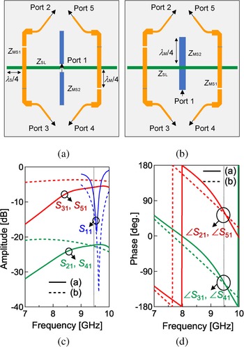
Figure 3 illustrates the simulated port layout and performance of the feed network of the proposed AIAA. The PIN diodes are connected at quarter-wavelength (λM/4) distance from the slot–microstrip junction. The slot lines are also extended up to quarter wavelength (λS/4) from the junction. Thus, the slot and microstrip lines are virtually connected at the junction. The two microstrip feed lines are symmetrical corresponding to the center of the layout. Each microstrip feed line has two PIN diodes but in alternative arrangement.
Layout of the feed network and simulated performance. Input port is denoted by 1, and output ports (2–5) are placed at the ends of the impedance transformers at the patch side. (a) Layout of the proposed feed network with loose coupling. (b) Layout of the whole feed network with tight coupling. (c) Simulated transmission coefficients. (d) Simulated phase difference.

Figure 3(a) shows the proposed antenna's feed network, which consists of microstrip line resonator of the Gunn oscillator at the bottom layer. The feed network has a single input port (port 1) and four output ports (ports 2–5). The total input power goes to the two among four output ports with equal amplitude but in anti-phase. A differential port is considered in place of the Gunn diode during the simulation. Moreover, a gap is considered between the slot lines to provide loose coupling with the microstrip–line resonator of the bottom layer. The relation between the characteristic impedance of the different kinds of transmission lines of the feed network in the proposed design can be expressed as follows:

To compare this proposed feed network with loose coupling, a similar feed network with tight coupling has been designed by utilizing a Z MS2 microstrip transmission line at the bottom layer and slot line with an impedance of Z SL at the ground layer as shown in Fig. 3(b). For effective power transfer, the output microstrip line impedance (Z MS1) at the top layer should be the same as the slot line impedance (Z SL). The relationship between the transmission lines are as follows:

Figures 3(c) and 3(d) show the comparison of the simulated S-parameters and phase of the output ports between the feed network arrangement shown in Figs 3(a) and 3(b). Here, the solid and dashed lines represent the designed feed network (Fig. 3(a)) and tight coupling (Fig. 3(b)), respectively. The term “tight coupling” is used to describe the feed network using equation (2). This feed network is designed for 9.47 GHz by using Z MS2 = 53 Ω for the tight coupling and Z MS2 = 107 Ω for the proposed feed network. It is seen from Fig. 3(c) that around 2-dB higher insertion losses (S 31, S 51) have been observed for the proposed feed network from the tight coupling (Fig. 3(b)) due to the loose coupling structure. Around 22-dB isolation is observed for the proposed feed network. The return loss (S 11) is better than 10-dB for both layouts at 9.47 GHz. The phase relationship of the feed network is important for the radiation of the array antenna. From Fig. 3(d), it can be seen that ports 3 and 5 get the signal in anti-phase (180°). Therefore, the array antenna can operate in-phase due to the arrangement of the ports 3 and 5.
Operation
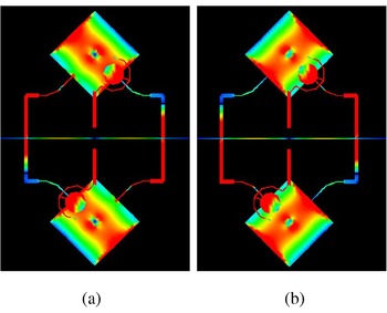
Figure 4 shows the electric current distribution of the proposed AIAA. To get the slant (either +45° or − 45°) polarization from the proposed AIAA, each patch antenna needs to be excited either one of the orthogonal feed networks. As the feed network contains four PIN diodes D1 to D4, switching voltage ensures either one of the orthogonal feed lines but in alternative manner excite the two 45° inclined patch elements. Here, diodes D1, D3 and D2, D4 account for the + 45° and − 45° polarization angle, respectively. It is clear from the figure that the two patch elements operate in-phase in both D1, D3 and D2, D4 ON conditions. As shown in Fig. 4(a), the array antenna provides + 45° polarization when the diodes D1 and D3 are set ON. In contrast, the proposed antenna generates − 45° polarization for D2, D4 ON condition.
Current distribution of the multi-layer array antenna for different switching states: (a) + 45° polarization for D1 and D3: ON and (b) − 45° polarization for D2 and D4: ON.

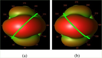
Figure 5 shows the simulated three-dimensional (3D) radiation patterns of the array antenna. The green lines in the middle of the 3D patterns show cutting planes of the antenna. In the ϕ = +45° plane, the peak of the radiation pattern can be found at θ = 0°. The radiation patterns of the array antenna in the ϕ = −45° plane are identical due to the symmetrical structure.
Simulated 3D radiation patterns of the proposed array antenna at 9.47 GHz: (a) D1, D3: ON (ϕ = +45°) and (b) D2, D4: ON (ϕ = −45°).

Effect of the Gunn oscillator
The structure and performance of the Gunn oscillator used in this study are described in [Reference Hasan, Nishiyama and Toyoda14]. The measured output power of the Gunn oscillator is around + 2.5 dBm at 9.47 GHz.
The radiation pattern of the single-layer polarization agile AIAA is shown in [Reference Hasan, Nishiyama and Toyoda33]. The Gunn oscillator was placed between the antenna elements. As a result, the patch spacing, d between the antenna elements cannot be optimized less than 1.2λ. The simulated gain was observed 5.76 dBi with high sidelobe levels, less than 5 dB low from the broadside direction, due to this constraint. Needless to say, the high sidelobe levels reduce the gain of the antenna and can be controlled by the patch spacing, d. Therefore, using the same layout but on a multi-layer structure is designed to improve the gain of the antenna. The Gunn oscillator is distributed on the different layers and hence, the optimization of the patch spacing is possible with a more compact structure.
Figure 6 shows the simulated gain comparison for the patch spacing of the antenna elements between the proposed antenna and an ideal array arrangement for 9.47 GHz. Here, the red and green lines pertain the simulated gain of the proposed antenna considering a differential port in place of the Gunn diode and without the feed network as shown in the inset of Fig. 6, respectively. Although the proposed antenna is designed for freedom to control the patch spacing, the quarter wavelength microstrip lines (λM/4) prevent the patch spacing less than 0.8 λ. Around 9.8 dBi gain is observed for d = 0.8 λ. This gain is 4.04 dB better compared to the single-layer structure. The discrepancy between the ideal and the proposed antenna is due to the feed network.
Simulated gain of the proposed antenna with respect to the patch spacing, d. Besides, an ideal 2-element array antenna's gain is shown for better understanding the impact of the feed network.

The radiation from the oscillator has an impact on the antenna's radiation in case of the single-layer structure. In [Reference Hasan, Nishiyama and Toyoda33], the polarizations were found at ± 55°, around 10° polarization shifting from the ideal ± 45°. Therefore, the multi-layer structure can effectively improve the performance of the antenna by distributing the oscillator on a different layer.
AIAA design
Figure 7 shows the dimension parameters of optimized layout of the proposed AIAA. The proposed antenna optimum parameter values are given in Table 1. The antenna is designed and optimized for X-band (9.5 GHz) by the Momentum of Keysight Technologies’ Advanced Design System (ADS). Here, L, W, g, and Z represent the length, width, gap, and impedance of the transmission lines, respectively. Two square patches with dimensions of L 1 = 10 mm are used. These patches are separated by d = 0.8λ0 ( = 25.36 mm) to achieve high gain based on the aforementioned discussion. Two slot lines with characteristics impedance of Z SL = 107 Ω (W 1 = 0.2 mm) are placed at the center with the gap of g 1 = 0.2 mm to loosely couple with the Gunn oscillator. In addition to that, the slot lines are extended by λS/4 = 6.2 mm from the slot–microstrip line junction for low loss slot-to-microstrip line transition. To facilitate the PIN diodes, 0.2 mm (g 2) gaps are used at λM/4 = 5.5 mm distance from the slot–microstrip line junction. The other optimized dimensions of the proposed AIAA are as follows: L 2 = 10.52 mm, L 3 = 6 mm, Z MS1 = 107 Ω, Z MS3 = 154 Ω, W 2 = 0.58 mm, and W 3 = 0.2 mm. At the bottom layer, a microstrip line resonator for the Gunn oscillator is placed with the following dimensions: Z MS2 = 107 Ω, L 4 = 5.9 mm, g 3 = 3.4 mm, and W 4 = 0.57 mm. For the biasing of the Gunn oscillator, a circular biasing pad is connected at the center of each half-wavelength high-impedance line (Z MS4 = 154 Ω). Moreover, square biasing pads with the dimensions of L 5 = 1.5 mm are used for the switching voltage. We employed 0.8-mm thick polytetrafluoroethylene substrates with a permittivity of 2.15 and conductor thickness of 0.018 mm due to its low dielectric constant and loss tangent (0.001 at 10 GHz).
Optimized layout of the proposed AIAA.

Final optimum parameter values of Fig. 7

Results
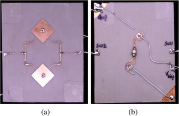
Figure 8 shows the photographs of the proposed polarization agile X-band AIAA prototype. The size of the prototype is 60 mm × 50 mm. Four PIN diodes of Skywork's DSG9500-000 and Microsemi's MG1052-30 Gunn diode are used in the proposed AIAA.
Prototype of the proposed X-band multi-layer AIAA (60 mm × 50 mm): (a) top layer and (b) bottom layer.

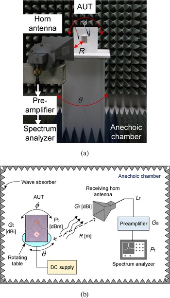
Figures 9(a) and 9(b) show the experimental figure and full measurement setup to investigate the EIRP, radiation pattern, and polarization characteristics of the proposed AIAA, respectively. The antenna is measured in an anechoic chamber using an Agilent E4407B spectrum analyzer and the performance of the antenna is evaluated by a receiving double-ridged horn antenna (TR17206, model no. 3115 by EMC Test Systems) with a gain of G r = 11.2 dBi. The antenna is kept at a distance (R) of 1.2 m to guarantee the far-field conditions. Due to the far distance, a preamplifier (G a = 30 dB) is utilized to improve the received signal level. The biasing cables of the power supply are covered by wave absorbers. The antenna can rotate along θ using a rotating table to measure the radiation pattern. Besides, the antenna is turned along ϕ as shown in Fig. 9 to check the polarization characteristics of the proposed AIAA.
Experimental setup for investigating the performance of the proposed polarization-agile AIAA. (a) Experimental figure in an anechoic chamber. (b) Measurement setup.

Figure 10 shows the measured oscillation characteristics of the proposed antenna as a function of Gunn oscillator's bias voltage at antenna's cutting plane ϕ = +45° for the diode condition D1 and D3 ON. Positive (+ 0.9 V, 20 mA) and negative (− 1.0 V, 20 mA) switching voltage are applied to turn ON the PIN diodes D1, D3 and D2, D4, respectively. The oscillation frequency can be tuned by the bias voltage of the Gunn diode. The maximum received power (P r) of − 0.1 dBm at 9.47 GHz is obtained for 7-V, 100-mA bias condition for the diode D1 and D3 ON condition. The EIRP can be calculated using the well-known Friis transmission formula shown in (3):

The EIRP of the proposed antenna is calculated as + 18.25 dBm (considering cable loss, L r = 6 dB). After taking the simulated gain (G t = 9.8 dBi) of the passive antenna, the transmitted power (P t) of the proposed AIAA becomes +8.45 dBm.
Measured oscillation characteristics of the proposed AIAA as a function of the Gunn oscillator's bias voltage when D1 and D3 are ON.

Figure 11 shows the measured free-running wideband power spectrum to show the effects of the patch elements. When all the PIN diodes are turned OFF, the patch elements are cut off from the input power and thus, lower received power of − 8.1 dB is observed compared to the diodes D1 and D3 ON condition. The reason to observe high received power for the diodes D1 and D3 ON condition is due to the gain of the antenna elements. However, around 1.7 dB difference between this 8.1 dB and the simulated gain of 9.8 dBi can be considered as the parasitic loss due to the PIN diodes. The oscillation frequency difference between the diodes D1, D3 ON and D1 to D4 OFF condition is because the antenna elements act like a load of the oscillator. An excellent second harmonic suppression of better than 37 dB is observed during the diodes D1 and D3 ON condition.
Measured free-running received wideband power spectrum at 7-V bias condition with respect to the PIN diode's condition. This graph includes cable loss (L r) and preamplifier gain (G a). The red and black lines represent the received power for condition of the diodes when D1, D3: ON and D1, D2, D3 and D4: OFF, respectively.

The measured lowest phase noise L(Δf) of the proposed AIAA is − 101.8 dBc/Hz at 1-MHz offset (Δf) from the oscillation frequency (f 0) at 9.47 GHz where the maximum power is obtained. A common figure of merit (FOM) is used to evaluate the performance of the oscillator. The FOM is defined as follows:

where P DC is the DC power consumption. The FOM of the proposed AIAA becomes − 152.9 dBc/Hz using equation (4).
Figure 12 shows the simulated and measured polarization characteristics of the proposed AIAA. Here, the solid and dashed lines represent the measured and simulated polarization characteristics, respectively. Besides, the black line pertains the diode condition D1 and D3 ON whereas the red line is for D2 and D4 ON condition. The polarization of the proposed AIAA is switched between ± 50° based on the diode conditions. Thus, the concept is found to be feasible. Moreover, the measured ± 50° polarization of the antenna is well matched with the simulated results. However, a small polarization imbalance has been observed between the conditions in the measurement due to the different amount of solder connections on the discrete PIN diode leads. Discrepancy is also observed between the simulation and measurement.
Measured and simulated polarization characteristics of the proposed AIAA.

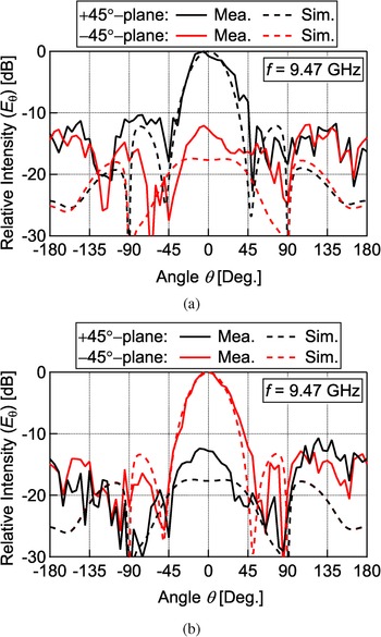
Figure 13 shows the normalized measured and simulated radiation patterns of the proposed AIAA. We recorded received power for each 5° rotation of θ using a spectrum analyzer. The recorded values are then normalized by the overall maximum value. Here, the black line represents the radiation of the antenna's cutting plane ϕ = +45° whereas the red means for − 45° plane. Although the measured results agree well with the simulated ones, some distortions are observed. We attribute these discrepancies to power jumping, temperature generated by the Gunn diode, unexpected scattering, and measurement errors. In both conditions, better than 12-dB cross-polarization suppression is achieved in the measurement.
Measured and simulated radiation patterns of the proposed AIAA: (a) D1, D3: ON and (b) D2, D4: ON.

Table 2 shows the summary of the measured results for the diode conditions. For diode condition D1 and D3 ON, the proposed AIAA shows + 50° polarization with transmitted power of + 8.45 dBm for 1.0 % DC-to-RF conversion efficiency. The EIRP is around + 18.25 dBm at 9.47 GHz. On the other hand, the proposed AIAA shows − 50° polarization and EIRP of + 18.0 dBm with +8.20 dBm of transmitted power at the same frequency for D2 and D4 ON condition. At this case, the DC-to-RF conversion efficiency is calculated as 0.95%.
Measured performance of the proposed AIAA with respect to the diode conditions

Table 3 shows the performance comparison with previously reported AIAAs. As there have not been so many papers reported on polarization agile AIAA, other reported AIAAs are also enlisted for broader comparison. Some information is calculated based on the available data found in those papers. Most of the AIAAs use transistors like HJFET, MESFET, and HEMT as they have much better DC-to-RF conversion efficiency, stability, and phase noise performance compared to the Gunn diode [Reference Ramesh, Bhartia, Bahl and Ittipiboon35]. Although many papers use several active devices, uniform characteristics are needed from each of those devices. Clearly, the performance of this proposed AIAA is very good. The high EIRP of better than 8.45 dB than [Reference Hasan, Nishiyama and Toyoda33] is achieved through the combination of high transmitted power from the oscillator and improved gain from the array antenna.
Comparison of the proposed antenna with previously reported antennas

a NA, not reported in literature.
b Calculated from given value.
Conclusion
In this paper, a polarization agile AIAA has been proposed for X-band applications. This proposed antenna can be used for the both wireless power transfer and communication systems. In the case of the power transfer system, this proposed AIAA performs as an RF power source. The polarization switching functionality can be used for spatial modulation in wireless communications. The proposed AIAA uses a multi-layer structure to improve its performance compared to the previously reported single-layer structure. A prototype antenna has been fabricated to validate the polarization switching functionality and self-oscillating capability. The proposed concept has been confirmed to be feasible. It is also possible to realize circular polarization switchable AIAA using this layout by introducing 90° phase difference between the fed patch.
Acknowledgements
The authors would like to thank Dr. Takayuki Tanaka, Saga University for his fruitful discussions. This work was supported by JSPS KAKENHI Grant Number JP17K06429.
 Maodudul Hasan received his B.Sc. degree in electronics and communication engineering from the Khulna University of Engineering and Technology (KUET), Khulna, Bangladesh, in 2014; his M.E. and Dr. Eng. degrees in communication engineering from Saga University, Saga, Japan in 2019 and 2022, respectively. From 2014 to 2017, he worked as a transmission engineer for Huawei Technologies Bangladesh Limited. Currently, he is working as an assistant professor at Saga University, Japan. His research interests include active integrated antennas and reconfigurable antenna design. He was the recipient of the honorable president award, Saga university; student presentation award, ICETC2020; SRW research committee award 2019; IEEE AP-S Japan student encouragement award 2019, Tokyo chapter; best paper award, APCAP2019 and ICSCT2021, and 2018 excellent student award of the IEEE Fukuoka section.
 Eisuke Nishiyama received his Doctor Engineering degree from Kyushu University in 2005. Currently, he is working as an associate professor with the Faculty of Science and Engineering at Saga University, Japan. From 2007 to 2008, he was a visiting scholar with the Electrical Engineering, University of California, Los Angeles (UCLA). His research interests are in reconfigurable microstrip antennas and rectennas. He served as a vice-chair of the IEEE Antennas and Propagation Society Fukuoka Chapter (2011–2012) and as a chair (2013–2014), respectively.
 Ichihiko Toyoda received his B.E., M.E., and Dr. Eng. degrees in communication engineering from Osaka University, Osaka, Japan, in 1985, 1987, and 1990, respectively. From 1990 to 2011, he was engaged in research and development of the three-dimensional (3-D) and uniplanar MMICs, ultra-high-speed digital ICs, millimeter-wave high-speed wireless access systems, and their applications at NTT Laboratories and NTT Electronics Corporation. He was also active in developing IEEE 802.11, 802.15, and other national standards. He is now a Professor and Dean of Faculty of Science and Engineering, Saga University, Japan. His current interests concern microwave circuit and antenna technology for advanced wireless systems. Dr. Toyoda has received many awards from IEICE, IEEJ, international conferences, and NTT. He was also recognized as an Excellent Educator by Saga University. He is a senior member of IEICE and a member of IEEE, EuMA and IEEJ.