I. INTRODUCTION
Owing to the low density and high specific mechanical properties, pure magnesium and its alloys have considerable potential for various engineering applications in automotive, aircraft industries, and electronics industries. Reference Yu, Zhang, Sun, Luo, Xu, Zhang and Pan1–Reference Xu, Nakata, Qiao, Zheng, Wu and Kamado3 However, there are several limitations of magnesium such as low ductility, high corrosion rate, poor creep, and abrasion resistance. Reference Chen, Zhao, Shu and Zhao4 To overcome these limitations, substantial efforts have been implemented to produce newly developed magnesium alloys and magnesium matrix composite by the addition of different type/size of reinforcements. Reference Deng, Li, Xu and Nie5,Reference Ye and Liu6 The addition of ceramic particles to the magnesium matrix has been shown one of the possible methods, in addition to alloying treatment. The shape, size, and distribution of the ceramic particles and their interface compatibility with the matrix could affect resultant properties of the developed magnesium matrix composite. Studies have shown that the mechanical properties of the nano-sized particles reinforced magnesium matrix composites with a low volume fraction were comparable or even superior to that of micron size particles reinforced composites with similar or higher volume fraction. Reference Chen, Xu, Choi, Pozuelo, Ma, Bhowmick, Yang, Mathaudhu and Li7
Nano-sized particles reinforced magnesium matrix composites are currently fabricated by liquid based or solid based processing techniques, which are similar to micro-sized particles reinforced magnesium matrix composites. For the solid based processing such as powder metallurgy, the metal powders, and nano-sized particles with reasonable composition were mixed by mechanical alloying or simple blending. Reference Goh, Wei, Lee and Gupta8,Reference Xi, Chai, Zhang and Zhou9 Secondary processing is necessary to further consolidate or shape the magnesium matrix composites. Other methods that involved to producing nano-sized particles reinforced magnesium matrix composites include disintegrated melt deposition, Reference Yao and Chen10 friction stir processing, Reference Azizieh, Kokabi and Abachi11 blend-press-sinter using hybrid microwave sintering, Reference Dieringa12 and semisolid stirring. Reference Wang, Hu, Wu, Zheng, Zheng and Zhai13 For the liquid based processing, the nano-sized particles are usually added into the crucible after the magnesium matrix is melted. Because of the strong self-aggregation tendency for large specific surface area and surface energy, it is difficult to uniformly disperse the nano-sized particles in molten magnesium, which directly reduce the strengthening effect. Reference Karbalaei Akbari, Baharvandi and Shirvanimoghaddam14
Thus, in order to achieve a uniform distribution before casting, a variety of methods are currently available to disperse the nano-sized particles in molten magnesium. The most common technology to disperse the nano-sized particles involves agitating the melt with a mechanical impeller (stir casting) while others propose the ultrasonic vibration related to transient cavitation and acoustic streaming. Reference Gupta and Wong15,Reference Lan, Yang and Li16 Alternatively, as a simple and effective liquid phase processing, ultrasonic vibration is sufficient to break up the clustered nano-sized particles, enhance wettability, and the degassing of magnesium melt. Reference Nie, Wang, Wu, Hu and Zheng17 However, the “push” effect of the solidification front on nano-sized particles can cause clusters along grain boundaries during the solidification process even if nano-sized particles distribute homogeneously in the magnesium melts. Reference Shen, Wang, Zhang, Hu, Zheng and Wu18,Reference Shi, Wang, Zhang, Li, Ding, Wu and Hu19 Squeeze casting involves the solidification of a molten metal in a closed die under an imposed high pressure, which could cause higher solidification rate and reduce gas and shrinkage porosities. Reference Hu20,Reference Zhou, Hu, Li and Lo21
The aim of this study is therefore to investigate the microstructure and mechanical properties of nano-sized particles reinforced magnesium matrix composite fabricated by ultrasonic vibration assisted squeeze casting. In addition, strengthening mechanisms for the traditional micro-sized particles reinforced magnesium matrix composite have been discussed in abundance of research. But not enough argumentations can demonstrate the strengthening mechanism for the nano-sized particles reinforced magnesium matrix composite.
Accordingly, in the present work nano-sized SiC particles reinforced magnesium matrix composites have been synthesized by ultrasonic vibration assisted squeeze casting. The mechanical properties and microstructures of the composite were studied and compared with that of matrix alloy. Strengthening mechanisms were also analyzed through theory analysis and experiment validation.
II. MATERIALS AND METHODS
A. Fabrication of nano-SiCp/AZ91 composite
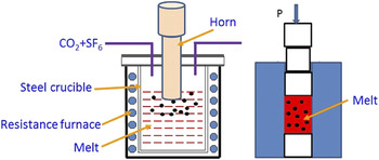
The matrix alloy was commercial AZ91 alloy with a nominal composition of Mg–9.07Al–0.68Zn–0.21Mn supplied by Northeast Light Alloy Company Limited (Harbin, China). The nano-sized reinforcements were SiC nanoparticles supplied by Hefei Kaier Nanometer Energy & Technology Company Limited (Hefei, China). The SiC nanoparticles reinforced AZ91 magnesium matrix composites were produced using ultrasonic vibration assisted squeeze casting. Figure 1 gives the experimental device schematic for nano-SiCp/AZ91 composite preparation. The maximum power and frequency of the ultrasonic vibration device are 2 kW and 20 kHz, respectively. First, about 1 kg of the AZ91 alloy was melt using an electric resistance furnace with an inlet of shielding gas (mixed CO2/SF6). Second, the SiC nanoparticles with aluminum foil wrapped was dipped into the magnesium melt at a temperature of 700 °C. Then the melt was subjected to ultrasonic vibration with different powers (350, 480, and 600 W) for 20 min at a temperature of 700 °C. At last, the melt was poured into a closed die (preheated to 450 °C) and solidified under an imposed high pressure. The volume content of SiC nanoparticles in the SiCp/AZ91 composites was 1%.
The experimental device schematic for nano-SiCp/AZ91 composite preparation.

B. Materials characterization
To investigate SiC nanoparticles distribution and the grain size of nano-SiCp/AZ91 magnesium matrix composite, the microstructural characterization were conducted on optical microscopy (OM), scanning electron microscopy (SEM), and transmission electron microscopy (TEM). The as-cast sample was ground with successive grades of SiC abrasive papers (SiC grit papers, Wuxi City Gangxia Precision Sand Paper Mill, Wuxi, China) from P600 to P4000 mesh. A solution of picric acid [5 mL acetic acid + 5.5 g picric acid + 100 mL H2O + 90 mL ethanol] was used as the etchant to reveal the microstructure. The grain size measurements were carried out by Image-Pro Plus (IPP) software (Media Cybernetics, Bethesda, Maryland). The specimens for TEM tests were made into a foil of 50 μm thickness prepared by grinding-polishing and then ion beam thinned. The tensile mechanical properties of as-cast nano-SiCp/AZ91 composites were measured using Instron 5569 universal testing machine (Instron Ltd., Shanghai, China) at room temperature. The initial strain rate for the tensile test was 8.33 × 10⁻⁴ (s−1). The tensile strength (yield strength, ultimate tensile strength, and elongation) reported in the work was averaged from 3 to 5 tensile tests.
III. RESULTS AND DISCUSSION
A. Fabrication of nano-SiCp/AZ91 composite
The ultrasonic intensity I in the melt which represents the sound power per unit area perpendicular to the direction of propagation can be expressed as Reference Ramirez, Qian, Davis, Wilks and StJohn22 :
 $$I = {1 \over 2}\rho c{\left( {2\pi fA} \right)^2}\quad .$$
Among them, ρ represents melt density, c represents ultrasonic velocity of the melt, f represents ultrasonic frequency, and A represents ultrasonic vibration amplitude. Research shows that enough cavitation effect can be produced in the aluminum melt and magnesium melt when the ultrasonic intensity I ≥ 80 W/cm2. Reference Ramirez, Qian, Davis, Wilks and StJohn22,Reference Eskin23 The experimental data related to the propagation velocity c in the melt is very little, but c value for metals with low melting points can be estimated as 1.3 × 10³ m/s or can be estimated as 1.5 × 10³ m/s in the water at a temperature of 20 °C. Reference Ramirez, Qian, Davis, Wilks and StJohn22 As the density and viscosity of magnesium melt is equivalent to water, it can be assumed that the propagation velocity c in the magnesium melt is 1.5 × 10³ m/s when density ρ of magnesium melt is 1.59 g/cm3. In the current work, the frequency of ultrasonic treatment was about 20 kHz for the preparation of nano-SiCp/AZ91 magnesium matrix composites. Assuming that ultrasonic horn is completely wetted with the magnesium melt, the ultrasonic intensity is 225 and 1400 W/cm2 as the ultrasonic vibration amplitude is 12 and 30 μm, respectively. Thus, wave length (λ = c/f) of ultrasonic propagation is about 80 mm and can meet the requirement of the test.
On the other hand, the ultrasonic cavitation effect can also be studied from acoustic intensity in the melt. The acoustic intensity P k which represents the pressure change on the unit cross-sectional area when ultrasonic spreads in the melt can be expressed as Reference Li, Momono, Tayu and Fu24 :
 $${P_{\rm{k}}} = {\left( {{{2P{\rho _{\rm{L}}}{C_{\rm{L}}}} \over S}} \right)^{1/2}}\quad .$$
Among them, P represents output power of the ultrasonic treatment apparatus, ρL represents melt density, C L represents propagation velocity of the ultrasonic wave in the melt, and S represents contact area between ultrasonic horn and melt. In the present work, the values of P, ρL, C L, and S are 2 kW, 1.59 g/cm3, Reference Eskin23 1.5 × 10³ m/s, and 19.63 cm2, respectively. The acoustic intensity P k in the melt is determined as 2.2 × 10⁶ Pa, which is greater than initial value 1 × 10⁶ Pa of sound intensity required to produce the cavitation effect. Based on the above calculation, the ultrasonic treatment device in this study can produce sufficient cavitation effect in the magnesium melt for the preparation of composites.
When the magnesium melt is subjected to ultrasonic vibration, the capillary effect in the melt will increase significantly, leading to the penetration of the melt into the agglomerated particles. The critical osmotic pressure can be obtained by the following equation Reference Chen, Li, Zhou and Wang25 :
 $${p_{\rm{s}}} = {{6\lambda {\sigma _{{\rm{LG}}}}\cos \theta \left( {\varphi - 1} \right)} \over {{d_{\rm{p}}} \times \varphi }}\quad .$$
Among them, d p represents average diameter of the particles, σLG represents surface tension of the melt, φ represents volume fraction of particle porosity, λ represents geometric factor, and θ represents contact angle between the particles and the melt. In the present work, the values of λ and d p are 1.4 and 60 nm, respectively, while the surface tension of magnesium melt at melting point is 0.559 N/m. Reference Chen, Li, Zhou and Wang25 Assuming that the SiC nanoparticles are completely wetted with the magnesium melt, the critical osmotic pressure is determined as 313 MPa to disperse the SiC nanoparticles in the magnesium melt. The ultrasonic pressure caused by cavitation effect is about 105 MPa in the melt subjected to ultrasonic vibration, which is much higher than the critical osmotic pressure required for the dispersion of nanoparticles. Thus, the agglomeration of nanoparticles can be broken up in the melt.
Above all, the ultrasonic device used in this paper can meet the requirements, and uniform dispersion of SiC nanoparticles is expected to achieve in the magnesium melt.
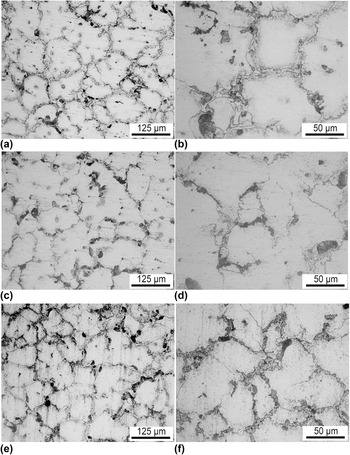
Figure 2 shows metallographic structures of nano-SiCp/AZ91 composites prepared under different ultrasonic power conditions. As can be seen from Fig. 2, grains of the composites are finer than that of the AZ91 alloy without ultrasonic vibration reported in our previous work. Reference Nie, Wang, Wu, Hu and Zheng17 This is mainly due to the fact that the addition of SiC nanoparticles can increase the number of nucleation sites during solidification and affect nonuniform nucleation for matrix alloy. On the other hand, Zenner pinning effect caused by SiC nanoparticles may also hinder the matrix grain growth, Reference De Cicco, Turng, Li and Perepezko26–Reference Xu, Chen, Choi and Li28 contributing to the refinement of matrix grains. Wang et al. Reference Wang, Wang, Zhao and Du29 studied the DSC cooling curve of AZ91 alloy and SiC nanoparticles reinforced magnesium matrix composites. Their results also showed that the SiC nanoparticles could be the nonuniform nucleation sites of matrix alloy and reduce the degree of undercooling during solidification, thus promoting grain refinement of the matrix. However, with increasing the ultrasonic power, the grain size of the matrix alloy is not changed obviously. In the one hand, in the present work ultrasonic vibration is only used to disperse nanoparticles in molten metals, not in solidifying melts. Thus, the α-Mg grains are not refined directly by the ultrasonic vibration in the present processing condition. In the other hand, SiC particles with the same volume fraction have been added to the matrix alloy. As a result, the effect of SiC nanoparticles on nonuniform nucleation and Zenner pinning of matrix alloy is also similar. Therefore, the grain size of the matrix alloy for all the composites with volume fraction of 1% is not changed obviously in the composite.
OM micrographs of nano-SiCp/AZ91 composite produced under different ultrasonic powers: (a) 350 W, (c) 480 W, (e) 600 W, and high magnification of (b) 350 W, (d) 480 W, (f) 600 W.

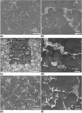
Figure 3 gives SEM micrographs of nano-SiCp/AZ91 composites prepared under different ultrasonic power conditions. As shown in Figs. 3(a) and 3(e), when the ultrasonic power is set as 350 or 480 W, a large number of plate-like β-Mg17Al12 phase exist in the composite. Most of β-Mg17Al12 phase in the AZ91 alloy is in the form of plates and mainly located at grain boundaries, as reported in our previous work.
Reference Nie, Wang, Wu, Hu and Zheng17
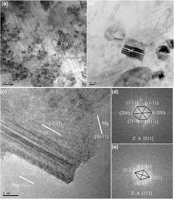
SEM observation at high magnification reveals that under the ultrasonic power of 350 W most of the plate-like β-Mg17Al12 phases are distributed along the grain boundaries in the composite as shown in Figs. 3(a) and 3(b). With increasing the ultrasonic power to 480 W, most of the β-Mg17Al12 phase is changed to fine and oriented lamellae as shown in Figs. 3(c) and 3(d). When the ultrasonic power is further increased to 600 W, as shown in Figs. 3(e) and 3(f), the amount of SiC nanoparticle clusters increases at the grain boundaries. To observe the nanoparticle distribution, TEM is used to analysis the microstructure of composite prepared under an output ultrasonic power of 480 W, as shown in Fig. 4. The homogeneous distribution of SiC nanoparticles can be found in the composite both at low and high magnifications in Figs. 4(a) and 4(b). This indicates that the present ultrasonic vibration assisted squeeze casting is capable of distributing and uniformly dispersing SiC nanoparticles in magnesium melt. The wettability of SiC nanoparticles by magnesium alloy is evaluated from HRTEM images of Mg17Al12/SiCp/Mg interface [Fig. 4(c)]. To obtain the corresponding Fourier transform spots, as shown in Figs. 4(d) and 4(e), Fourier transform (FFT) were performed in the area of the β-Mg17Al12 phase and SiC nanoparticles, respectively. It can be seen from Fig. 4(d) that crystal axis for the fcc SiC is [011]. The angle between the (1−11) plane and (−200) plane is 54.74° while the angle between (1−11) plane and (−1−11) plane is 70.52°. With regard to the bcc Mg17Al12, as shown in Fig. 4(e), crystal axis is [113]. The angle between the (−1−21) plane and (−521) plane is 81.43°, while the angle between (−521) plane and (12−1) plane is 98.57°. Based on the HRTEM image analysis, there are some orientation relationship between the Mg17Al12 phase and SiC, i.e.,
 ${[113]_{{\rm{M}}{{\rm{g}}_{{\rm{17}}}}{\rm{A}}{{\rm{l}}_{12}}}}{\parallel} {[011]_{{\rm{SiC}}}}$
.
SEM micrographs of nano-SiCp/AZ91 composites fabricated under different ultrasonic powers: low magnification (a) 350 W, (c) 480 W, and (e) 600 W, high magnification (b) 350 W, (d) 480 W, and (f) 600 W.

TEM micrographs of nano-SiCp/AZ91 composites fabricated at power level of 480 W: (a) low magnification of SiC nanoparticles, (b) higher magnification of SiC nanoparticles, (c) HRTEM image of Mg/SiC/Mg17Al12 interface, (d) FFT diffraction patterns of SiC, and (e) FFT diffraction patterns of Mg17Al12.

There is no obvious change of grain size while the morphology of β-Mg17Al12 phase is significantly affected for nano-SiCp/AZ91 composites by the change of ultrasonic power. With the increase of the ultrasonic treatment power, the number of plate-like β-Mg17Al12 phase changed to fine lamellae increases first and then decreases in the composites. When the ultrasonic power is low, some SiC nanoparticles can not be effectively broken up by cavitation effect and acoustic flow effect. It should be noted that ultrasonic vibration is only used to disperse nanoparticles in molten metals, not in solidifying melts. Although there are a few microscopic particles of active insoluble solid impurities in magnesium melt, such as Mn-based intermetallics, Reference Cao, Ma and StJohn30 effective heterogeneous nucleation cannot be formed during solidification. As the number of nucleation particles is less in the solidification process, the number of nucleation sites related to the “push” effect of the solidifying interface is also reduced along the grain boundaries. As a result, most of the β-Mg17Al12 phases are still in plate-like at low power. With the increase of the ultrasonic treatment power, more SiC nanoparticles and activated micro-particles consisted of insoluble solid impurities in the melt may become the nucleation sites. The number of nucleation sites along the grain boundaries related to the “push” effect of the solidifying interface is also increased. In addition, the melt was solidified in a closed die under an imposed high pressure, which cause higher solidification rate and has great effect on the size and distribution of precipitation. Thus, the distribution of most β-Mg17Al12 phases changes from plate-like to oriented lamellae with increasing the power of ultrasonic treatment. However, in the current work the ultrasonic power depends on the depth of the ultrasonic probe dipped into the melt. As a result, the effective action area of ultrasonic cavitation decreases with the increase of ultrasonic power. Thus, the obvious agglomerates of SiC nanoparticles along grain boundaries are observed in the composite fabricated with ultrasonic power of 600 W. Therefore, reasonable selection of ultrasonic treatment power is beneficial to the dispersion of SiC nanoparticles.
B. Strengthening mechanism of nano-SiCp/AZ91 composite
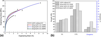
Figure 5 shows the engineering stress-engineering strain curves and tensile strength of nano-SiCp/AZ91 composites fabricated under different ultrasonic powers. It can be seen from Fig. 5 that the ultimate tensile strength, yield strength, and elongation to fracture of the composites fabricated under different ultrasonic powers are simultaneously improved compared with the AZ91 alloy. The phase Mg17Al12 constitutes a continuous brittle phase along the grain boundaries of α-Mg dendrites in the as-cast AZ91 alloy, which decreases the tensile strength. As shown in Figs. 2(a) and 2(c), the amount of the refined phase Mg17Al12 in the composite increases compared with the as-cast AZ91 alloy. Moreover, as shown in Figs. 4(a) and 4(b), the homogeneous distribution of SiC nanoparticles can also strength the composites fabricated at 480 W power level. However, there is a significant reduction in the ultimate tensile strength and elongation to fracture in the composite fabricated by ultrasonic vibration at 600 W power level. This can be attributed to the increase of agglomeration of SiC nanoparticles along grain boundaries and decrease of amount of refined phase Mg17Al12 with higher ultrasonic power as shown in Figs. 2(f) and 3(f).
(a) The engineering stress-engineering strain curves and (b) tensile strength of nano-SiCp/AZ91 composites fabricated under different ultrasonic powers.

The mechanical properties of metal matrix nanocomposites are affected by many factors, including preparation methods, the grain size of matrix alloy, and the strength and thermal expansion coefficient of the matrix and the reinforcement. The main reinforcing mechanisms for metal matrix nanocomposites include Hall–Petch strengthening, Orowan strengthening, Taylor strengthening, and load transfer mechanism.
1. Hall–Petch strengthening mechanism
Hall–Petch strengthening mechanism is mainly used to describe the effect of grain refinement on the mechanical properties of materials. Usually finer the grain, higher the yield strength of the material. This strengthening mechanism can be described by the Hall–Petch equation Reference Ye and Liu6,Reference Chen, Lin, Shu, Hu, Zhao, Kang, Huang and Yuan31,Reference Xu, Nakata, Qiao, Zheng, Wu and Kamado32 :
 $${\sigma _{\rm{y}}} = {\sigma _0} + {k_{\rm{y}}}{d^{ - 1{\rm{/}}2}}\quad ,$$
where σ0 represents initial strength of the material, and the unit is MPa; k y represents material constant, depending on crystal structure of the material, and the unit is MPa/m1/2; d represents grain size, and the unit is m. For metal matrix nanocomposites, grain size of the matrix alloy is mainly related to the size and volume fraction of the reinforcement. With the decrease of nanoparticles size or the increase of the volume fraction, the grain size of the matrix alloy usually decreases. Because the number of enabled slip systems is few for the magnesium alloy and its composites, the mechanical properties are significantly affected by grain refinement. In the present work, the yield strength of nano-SiCp/AZ91 composite is obviously improved compared with AZ91 alloy. The increase of yield strength caused by grain refinement can be expressed by Hall–Petch strengthening mechanism Reference Zhang and Chen33 :
 $$\Delta {\sigma _{{\rm{Hall}}-{\rm{Petch}}}} = {k_{\rm{y}}}\left( {{d_{{\rm{nc}}}}^{ - 1/2} - {d_{\rm{m}}}^{ - 1/2}} \right)\quad ,$$
where d nc represents the grain size of the matrix in the nano-SiCp/AZ91 composite while d m represents the grain size of the AZ91 alloy. For Mg-based material the value of k y is determined as 0.133 MPa/m1/2. Reference Zhang and Chen33
2. Orowan strengthening mechanism
The mismatch in thermal expansion coefficients and elastic modulus between the matrix and reinforcement can generate geometrically necessary dislocations in the metal matrix composite. For the micro-particle reinforced metal matrix composites, the particles with large particles spacing are prone to distribute along grain boundaries. Thus, it is generally believed that the Orowan strengthening mechanism is not significant for micro-particle reinforced metal matrix composites (usually with a particle size greater than 5 μm). Reference Zhang and Chen33 As for nanoparticle reinforced metal matrix composites, the particles size and particles spacing of nanoparticle are small, which impedes the movement of dislocations. The volume fraction of nanoparticle is usually no more than 2% and the dislocations need to bypass the nanoparticles using Orowan bow, so the Orowan strengthening mechanism is an important mechanism for the metal matrix nanocomposites. Reference Shao, Vereecken, Chien, Searson and Cammarata34 For magnesium matrix nanocomposites, the Orowan strengthening mechanism can be expressed as Reference Zhang and Chen33,Reference Hassan, Tan and Gupta35–Reference Chen, Shu, Hu, Zhao and Yuan38 :
 $$\Delta {\sigma _{{\rm{Orowan}}}} = {{0.13{G_{\rm{m}}}b} \over {{d_{\rm{p}}}\left[ {{{\left( {1{\rm{/}}2{v_{\rm{p}}}} \right)}^{1/3}} - 1} \right]}}\ln \left( {{{{d_{\rm{p}}}} \over {2b}}} \right)\quad ,$$
where d p represents diameter of the nanoparticles, and the unit is m; G m is shear modulus of the matrix alloy, and the unit is MPa; b represents Burgers vector of the matrix, and the unit is m; v p represents the volume fraction of the nanoparticles. For nano-SiCp/AZ91 magnesium matrix composites, the volume fraction v p of SiC nanoparticles is 1% and the average diameter d p is about 60 nm. The values of G m and b for matrix alloy are 17.3 GPa and 0.32 nm, respectively. Reference Cao, Choi, Oportus, Konishi and Li39
3. Taylor strengthening mechanism
Taylor strengthening mechanism is commonly used to evaluate the effect of dislocation density on the strength of the material. During the hot extrusion or hot compression, the residual plastic strain related to work hardening or mismatch in thermal expansion coefficients and elastic modulus between the matrix and reinforcement can lead to the generation of dislocation in the composite. The strength change due to mismatch of elastic modulus and work hardening is ulually negligible for nanocomposites. Reference Sanaty-Zadeh40 The enhancement effect due to thermal mismatch for the nanocomposite can be expressed as Reference Zhang and Chen33,Reference Hassan, Tan and Gupta35,Reference Zhang and Chen36,Reference Chen, Shu, Hu, Zhao and Yuan38 :
 $${\sigma _{\rm{d}}} = M\beta {G_{\rm{m}}}b\sqrt {{\rho ^{{\rm{CTE}}}}} \quad ,$$
where M represents Taylor factor; β represents constant; G m represents the shear modulus of the matrix; b represents Burgers vector of the matrix. ρCTE is the density of geometric dislocation resulting from mismatch in thermal expansion coefficients between the matrix and reinforcement, and can be described by Reference Dai, Ling and Bai41 :
 $${\rho ^{{\rm{CTE}}}} = {{A\Delta \alpha \Delta T{v_{\rm{p}}}} \over {b{d_{\rm{p}}}}}\quad ,$$
where A is the geometric constants and the value is in the range of 10–12, depending on the geometric characteristics of the particles. For the equal-axis particles, the value of A is 12. Δα represents the difference in thermal expansion coefficients between the matrix and reinforcement; ΔT is the temperature difference between material preparation and mechanical measurements; v p is the volume fraction of the particles; b is the Burgers vector of the matrix; d p is the diameter of the particles. The increase in the yield strength of magnesium matrix composites due to thermal mismatch for the composite can be expressed as Reference Zhang and Chen33,Reference Dai, Ling and Bai41,Reference Goh, Wei, Lee and Gupta42 :
 $$\Delta {\sigma _{{\rm{CTE}}}} = \sqrt 3 \beta {G_{\rm{m}}}b\sqrt {{{12\left( {{T_{{\rm{process}}}} - {T_{{\rm{test}}}}} \right)\left( {{\alpha _{\rm{m}}} - {\alpha _{\rm{p}}}} \right){v_{\rm{p}}}} \over {b{d_{\rm{p}}}}}} \quad ,$$
where the value of β is given as 1.25; T process and T test are the temperature of material preparation and mechanical measurements, respectively. αm and αp are thermal expansion coefficients of the matrix and reinforcement, respectively. For nano-SiCp/AZ91 magnesium matrix composites, the values of αm for AZ91 alloy is 30.7 × 10⁻⁶ (°C)−1, Reference Cao, Choi, Oportus, Konishi and Li39 while αp of SiC nanoparticles is 4.6 × 10⁻⁶ (°C)−1. Reference Xu, Nakata, Qiao, Zheng, Wu and Kamado32
4. Load transfer mechanism
The good interfacial bonding between the dispersed particles and the matrix contributes to the transfer of the load applied to the material to the reinforcement. The load transfer mechanism can be described by the following equation Reference Nguyen and Gupta43 :
 $$\Delta {\sigma _{\rm{l}}} = {v_{\rm{p}}}{\sigma _{\rm{m}}}\left[ {{{\left( {1 + t} \right)A} \over {4l}}} \right]\quad ,$$
where σm is the yield strength of the matrix; l is the dimension of the reinforcement particles parallel to the loading direction; t is the thickness of the particles; A = l/t is the aspect ratio of the particles.
Assuming that the SiC nanoparticles are equiaxed, the increase in the yield strength resulting from the load transfer effect in the magnesium matrix nanocomposites can be expressed as Reference Xu, Nakata, Qiao, Zheng, Wu and Kamado32,Reference Zhang and Chen36,Reference Chen, Shu, Hu, Zhao and Yuan38,Reference Dai, Ling and Bai41 :
 $$\Delta {\sigma _{\rm{l}}} = 0.5{v_{\rm{p}}}{\sigma _{\rm{m}}}\quad .$$
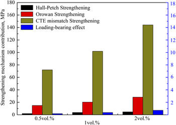
According to the alloy phase diagram, the solidus temperature of nanocomposite is assumed to be 468 °C for the as-cast nano-SiCp/AZ91 composites. Thus, the yield strength increase for the composites is shown in Fig. 6 based on the above-mentioned mechanisms. The yield strength of SiC nanoparticle reinforced magnesium matrix composite with volume fraction of 0.5 and 2% given in Fig. 6 are published in our preliminary study. Reference Nie, Wang, Wu, Hu and Zheng17 It can be seen from Fig. 6 that the increase in yield strength due to the load transfer mechanism is less than 1 MPa. Because the volume fraction of SiC nanoparticles is usually not high (not more than 3 vol%), and the load transfer mechanism can be ignored for nanocomposites. It can also be seen from Fig. 6 that the theoretical increase due to the thermal mismatch strengthening mechanism is much higher than the experimental values. When the temperature of the nanocomposite decreases from T 0 to T 1, the temperature change ΔT = T 0 − T 1 can lead to the generation of thermal mismatch strain εCTE. The value of εCTE can be estimated by:
 $${\varepsilon _{{\rm{CTE}}}} = \left( {{\alpha _{\rm{m}}} - {\alpha _{\rm{p}}}} \right)\Delta T = \Delta \alpha \Delta T\quad .$$
The yield strength increase for the nano-SiCp/AZ91 composites based on different strengthening mechanisms.

For nondeformable particle reinforced composites, the thermal mismatch strain can be hindered by the particles. To coordinate this thermal mismatch deformation, a large number of geometrically necessary dislocation loops would generate around the particle surface. The number of dislocation loops n CTE on a single particle surface due to thermal mismatch can be approximately estimated by:
 $${n^{{\rm{CTE}}}}b{A_{\rm{p}}} = \Delta {v_{\rm{p}}}\quad .$$
where the area of the dislocation loop can be determined by
 ${A_{\rm{p}}} = {1 \over 4}\pi d_{\rm{p}}^2$
; the volume change due to thermal mismatching is given by
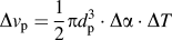 $\Delta {v_{\rm{p}}} = {1 \over 2}\pi d_{\rm{p}}^3 \cdot \Delta \alpha \cdot \Delta T$
. So the value of n
CTE can be expressed as:
 $${n^{{\rm{CTE}}}} = {{2{d_{\rm{p}}}\Delta \alpha \cdot \Delta T} \over b}\quad .$$
If the length of each dislocation loop is taken as πd
p, then the geometrically necessary dislocation density
 $\rho _{\rm{G}}^{{\rm{CTE}}}$
for thermal mismatch is:
 $$\rho _{\rm{G}}^{{\rm{CTE}}} = {{12{v_{\rm{p}}}\Delta \alpha \cdot \Delta T} \over {b{d_{\rm{p}}}}}\quad .$$
Taking the average particle size of 10 μm and 60 nm as an example, when volume fraction of the particle is the same, the ratio
 $\rho _{\rm{G}}^{{\rm{CTE}}}$
(60 nm):
 $\rho _{\rm{G}}^{{\rm{CTE}}}$
(10 μm) of geometrically necessary dislocation density for thermal mismatch is 167 according to Eq. (15). The increase ratio ΔσCTE (60 nm):ΔσCTE (10 μm) in yield strength is 12.9 for the composite with different reinforcement particle size according to Eq. (9). And for the volume fraction 1% composites with average particle size of 60 nm and the volume fraction 10% composites with average particle size of 10 μm, the ratio
 $\rho _{\rm{G}}^{{\rm{CTE}}}$
(60 nm):
 $\rho _{\rm{G}}^{{\rm{CTE}}}$
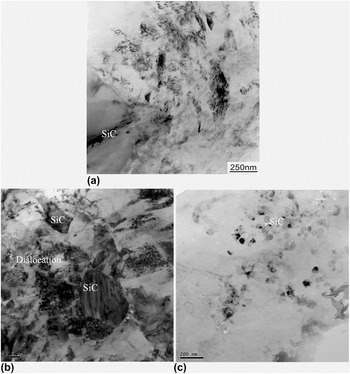
(10 μm) of geometrically necessary dislocation density for thermal mismatch is 16.7 according to Eq. (15). The increase ratio ΔσCTE (60 nm):ΔσCTE (10 μm) in yield strength is 4 for the composite with different particle size according to Eq. (9). The theoretical increase in the yield strength of the nanoparticles reinforced composite obtained from Eq. (9) is much larger than that of the micro-particle reinforced composite. The increase of the yield strength due to thermal mismatch for the nanocomposites according to Eqs. (12)–(15) is not consistent with the experimental result. It should be noted that Eqs. (12)–(15) are proposed for micro-particle reinforced composites. When the average diameter of the nanoparticles is reduced, internal stresses due to the mismatch in the thermal expansion nanoparticle and matrix is decreased. Yet there would be few dislocation generates due to thermal mismatch between the matrix and the reinforcement in the present nanocomposites. The interfaces between SiC particles and matrix for composites with different SiC particle sizes are observed by TEM, as shown in Fig. 7. It can be found that the dislocation density is high at the interface for the composites with SiC particles size of 10 μm while few dislocation is found near the interface between the particles and the matrix for the composites with SiC particles size of 60 nm. Besides, a large number of dislocations formed due to thermal mismatch are thermodynamically unstable crystal defects, making the material with high energy unstable. When the volume fraction is the same, the smaller the size of SiC particles, the larger the number of SiC nanoparticles. Thus, to reduce the materials energy, the addtiton of SiC nanoparticles with larger surface area may not cause the formation of large dislocations. According to the analyses above, the thermal mismatch strengthening mechanism can be negligible for the current as-cast magnesium matrix nanocomposites.
TEM micrographs of magnesium matrix composites reinforced by SiC particles with different particle size: (a) 10 μm SiCp/AZ91, (b) 1 μm SiCp/AZ91, (c) 60 nm SiCp/AZ91.

Therefore, in the present work, the yield strength of the cast nano-SiCp/AZ91 composites is mainly related to Hall–Petch strengthening mechanism and Orowan strengthening mechanism. To obtain a suitable model to evaluate the strengthening mechanism of nanocomposites, summation method and square root method were used to calculate the theoretical increase in the yield strength for nanocomposites. The theoretical increase in the yield strength for nanocomposites by the summation method can be described as:
 $$\Delta \sigma = \Delta {\sigma _{{\rm{Hall}}-{\rm{Petch}}}} + \Delta {\sigma _{{\rm{Orowan}}}}\quad .$$
The theoretical increase in the yield strength for nanocomposites by square root method is given as:
 $$\Delta \sigma = \sqrt {{{\left( {\Delta {\sigma _{{\rm{Hall}}-{\rm{Petch}}}}} \right)}^2} + {{\left( {\Delta {\sigma _{{\rm{Orowan}}}}} \right)}^2}} \quad .$$
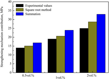
Based on the yield strength for nanocomposites with volume fraction of 0.5 and 2% in our previous study, Reference Nie, Wang, Wu, Hu and Zheng17 the experimental results for nano-SiCp/AZ91 composites with different volume fractions were compared with the calculated values as shown in Fig. 8. It can be seen from Fig. 8 that the theoretical values of nanocomposites obtained by the square root method approximates to the experimental values. In the theoretical calculations SiC nanoparticles are assumed to be perfectly homogeneous and distributed within the grains. But a portion of the SiC nanoparticles are found to be distributed along the grain boundaries in the current experiments. This leads to the decrease of the Orowan strengthening mechanism, as well as the difference between experimental values and theoretical calculations for the present nanocomposites.
The total increment of yield strength of theoretic and experiment value using different models.

IV. CONCLUSIONS
In the present work nano-sized SiC particles reinforced magnesium matrix composites have been successfully synthesized by ultrasonic vibration assisted squeeze casting. The relation between performance and microstructure is studied and strengthening mechanisms are also analyzed using theoretical and experimental methods. Based on the obtained results, the following conclusions can be made:
-
(1) According to theoretical calculations, uniform dispersion of SiC nanoparticles in the magnesium melt is expected to achieve using the ultrasonic device.
-
(2) The grains of the nano-SiCp/AZ91 composites are refined compared with the AZ91 alloy. This can be attributed to the increase of nucleation sites during solidification and Zenner pinning effect caused by the addition of SiC nanoparticles.
-
(3) There is no obvious change in grain size for composites by the variation of ultrasonic power, while the morphology of β-Mg17Al12 phase is significantly affected.
-
(4) The ultimate tensile strength, yield strength and elongation to fracture of the composites fabricated under different ultrasonic powers are simultaneously improved compared with the AZ91 alloy.
-
(5) The increase of yield strength is mainly related to Hall–Petch strengthening and Orowan strengthening for the present composites. The theoretical value of the yield strength obtained by the square root method approximates to the experimental value.
ACKNOWLEDGMENTS
This work was financially supported by “National Natural Science Foundation of China” (Grant Nos. 51401144 and 51471059), and the “Natural Science Foundation of Shanxi” (Grant No. 2015021067).