One-dimensional nanoscale materials have attracted great attention.Reference Baughman, Zakhidov and Heer1 Among them, graphitic carbon nanotubes (CNTs) are one of the most interesting cases because of their unique electronic properties and many potential applications.Reference Subramoney2 Several methods such as electronic arc discharge, laser ablation, and chemical vapor deposition (CVD) of small hydrocarbons over metallic catalysts are commonly used to prepare CNTs.Reference Krueger3 Among them, the CVD method is particularly attractive for the synthesis of aligned CNTs in the gas phase. Controllable solid state pyrolysis of organometallic precursors has recently emerged as an alternative method for preparing carbon nanostructures such as CNTs and carbon onions.Reference Li, Dai, Huang, Mau and Wang4 In such a process, the organometallic complexes serve as both the catalyst precursors and as carbon sources, and the pyrolysis is carried out not in the gas phase but in the solid state at “low” temperatures.
Phthalocyanine (Pc) is a planar heterocyclic molecule of about 1.3 nm diameter having four fused together phenyl and pyrrole subunits. The Pc macromolecule is able to coordinate various metal cations (Fe, Ni, Co, etc.) in its center with the four central nitrogen atoms belonging to the pyrrolic subunits. With iron, this is called iron phthalocyanine (FeC32H16N8, FePc), which is useful in CNT synthesis.Reference Gao, Huang, Dai, Wallace, Gao and Wang5 However, all these methods need a supply of hydrogen to maintain the activity of catalysts during the high-temperature process (800–1300 °C). Furthermore, bulk synthesis of CNTs from a simple, controllable, and low-cost method is still a critical target in scientific and industrial research. To conquer the shortages of the low molecular weight Pc as carbon source, the use of Pc polymer, which has extremely good thermal properties and high char yields upon thermal treatment to elevated temperatures,Reference Laskoski, Dominguez and Keller6 as only carbon source for the formation of CNTs in the solid phase is an intriguing idea.
In this work, bulk synthesis of iron nanowire inside CNTs from FePc polymer in nitro atmosphere under 800 °C is presented for the first time. The excellent volume electrical resistivity of the iron nanowire inside CNTs is 9.0 × 10⁻³ Ω·cm−1. The iron nanowire inside carbon tubes from the metal Pc polymer possessed excellent electromagnetic loss properties, and the presence of the magnetic nanoiron inside CNTs provided the materials with novel magnetic loss properties.
Ten-gram 4, 4′-bis (3, 4-dicyanophenoxy) biphenyl and 12-mL N-methyl-2-pyrrolidone were added to a 100-mL three neck round bottle flask equipped with a mechanical stirrer and refluxing condenser, the mixture was heated at 180 °C for few minutes to dissolve sufficiently, then the solution was cooled to room temperature, and 0.4-g nanoiron particles were added to the bottle with vigorous stirring. The mixture was refluxed at 200 °C for 4 h. Finally, a dark green oligomer solution was obtained. Then the solution was poured to water with vigorous mechanical stirring, the excess iron was removed with a Millipore filter. The oligomer was cured in the oven by the procedure as follows: 250 °C, 4 h; 280 °C, 4 h; 300 °C, 50 h. So the completely cured FePc polymer with considerable magnetic properties was obtained.Reference Jia, Zhao, Zhong and Liu7
The preparation of solid nanoiron inside CNTs from FePc polymer was carried by heating under N2 atmosphere at 5 °C·min−1 to 300 °C (isotherm for 1 h); 5 °C·min−1 to 350 °C (isotherm for 1 h); 5 °C·min−1 to 400 °C (isotherm for 1 h); 3 °C·min−1 to 500 °C (isotherm for 4 h); 2 °C·min−1 to 800 °C (isotherm for 8 h).
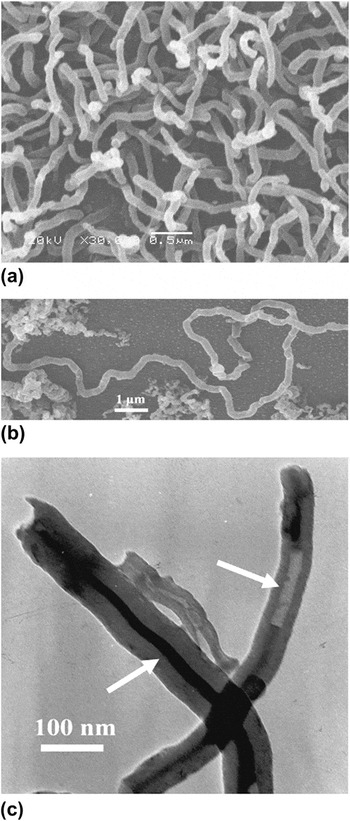
Scanning electron microscopy (SEM) images [Fig. 1(a)] were obtained with the iron loading at 4 wt% in the oligomer. Figure 1(a) showed an abundant amount of CNTs and long individual CNT stranded in a random morphology. Many nanotubes showed a little winding morphology and had a length up to several tens of micrometers [Fig.1(b)]. With an enhancement in the resolution, it appeared that the nanotubes were quite uniform and were around ∼90 nm in diameter. Transmission electron microscopy (TEM) reveled that the nanotubes were multiwalled CNTs with a diameter of ∼90 nm and a wall thickness of ∼30 nm [Fig. 1(c)]. According to the TEM, ≈90% of these tubes was filled with iron wire, thus affording unique metal core/carbon sheath nanocables [Fig. 1(c)]. The filled part of the tube was 1 to 10 μm in length, significantly longer than that of other metal-filled CNTs prepared by the arc discharge method.Reference Paul, Hsu, Barres and Chamers8 The filled spindle-like tip was closed, whereas the unfilled part of the cable was empty [indicated by the arrows in the Fig. 2(c)].
Scanning electron microscopy and Transmission electron microscopy images of iron nanowire inside carbon nanotubes (CNTs).

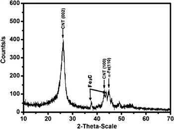
X-ray diffraction data for sample iron nanowire CNTs.

X-ray diffraction (XRD) scans of the samples were obtained using Cu Kα radiation from a rotating x-ray source (Fig. 2). All the diffraction peaks were identified and indexed on the basis of CNTs and Fe nanoparticles. The peaks at 25.79 (002), 43.07 (100) degrees resulted from the structure of CNTs,Reference Burian, Dore, Fischer and Sloan9 and the peak at 43.58 (110) degree was attributed to the α-Fe phase. The interplanar spacing for the CNTs (002) peak was calculated to be 3.38 Å. There appears to be little unordered or amorphous carbon present in the sample.
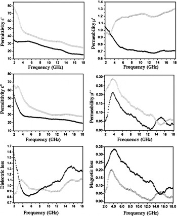
Figure 3 showed the frequency dependence of the real part (ε′) and imaginary part (ε′′) of relative complex permittivity of the iron nanowire inside CNTs sample. It could be found that the values of ε′ and ε′′ declined from 34.3 to 15.0 and from 51.1 to 19.7, respectively, over the 2–18 GHz frequency range. According to the free electron theory,Reference Wu and Kong10 ε′′ ≈1/2πε0ρf, where ρ is the resistivity. It could be speculated that the lower ε′′ values of iron nanowire inside CNTs at 2–18 GHz indicated a higher electric resistivity with respect to the other CNTs materials, e.g., ε′′ = 64.1–27.8 for CNTs. The higher electric resistivity may result from the few point defects existing in iron nanowire inside CNTs composites, the effective dispersion of iron nanowire, and the protective CNTs shells outside the iron nanowire. Figure 3 also showed a higher dielectric loss of the iron nanowire inside CNTs than CNTs at the frequency from 8 to 18 GHz. It was reasonable that dielectric loss was attributed to the lags of polarization between the core/shell interfaces as the frequency was varied. In the range of low frequency of 3–8 GHz, the iron nanowire inside CNTs had a low-dielectric loss. According to Refs. Reference Han and Deng11,Reference Deng and Han12, there were many factors making contributions to the dielectric properties: dielectric relaxation, resonance, the motion of conduction electrons, defects in the nanotubes, length, diameters, chirality, and so on. Therefore, it was extremely difficult to describe the permittivity dispersion behaviors of CNTs when taking into account of all these factors. As described above, the defects did not significantly alter the CNTs band structures, but it was possible that the defects may simply act as polarized centers. And the iron nanowire filled CNTs altered the band structures in the low frequency by generating additional states near to the Fermi level. It was reasonable that the dielectric core/sheath interfaces as the frequency was varied. In general, the high electric resistivity and proper dielectric loss are favorable to the improvement of the microwave absorption properties.
Electromagnetic properties of the iron nanowire inside CNTs (▲) and CNTs (Δ: supplied with China New Materials Company, without any further purification).

Figure 3 also shows the relative complex permeability of the iron nanowire inside CNTs sample. It revealed that the real part (μ′) exhibited an abrupt decrease from 1.0 to 0.7 at the 2–7 GHz range and retained an approximate constant over 7–18 GHz. Meanwhile the imaginary part (μ′′) increased from 0.20 to 0.29 at 2–5 GHz and then decreased in high frequency. It was note worthy that the maximum value of the μ′′ appearing at 3.6 GHz implied that the natural resonance occurred in the present iron nanowire. The magnetic loss (μ′′/μ′) were measured at the frequency range of 2–18 GHz, compared with the pure CNTs, the maximum value of magnetic loss of iron nanowire inside CNTs was about 0.35, where the pure CNTs were no more than 0.20 at the frequency of the 4.0–5.0 GHz, and for the measured frequency, the iron nanowire inside CNTs always had a higher value than that of the pure CNTs.
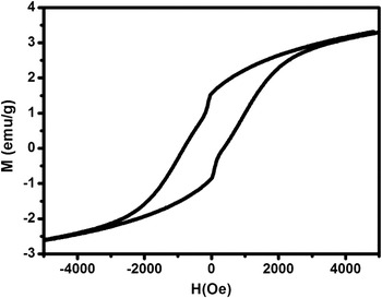
The magnetic properties of the iron nanowire inside CNTs were investigated with a vibrating sample magnetometer. Figure 4 shows the magnetization curves measured at 300 K with the iron loading at 4% in the oligomer, the typical ferromagnetic material was exhibited with the magnetic saturation value is ∼3.5 emu/g, whereas the coercive force was ∼594.0 Oe. All the microwave properties discussed above showed that the bulk synthesis of multiwalled CNTs filled with iron nanowire from the solid state pyrolysis of nanoiron Pc polymer was a very interesting way to get novel electromagnetic absorption materials.Reference Ajayan, Colliex, Lambert, Bernier, Barbe-dette, Tenc and Stphan13
Room-temperature magnetization curve of iron nanowire inside CNTs.

The conversion of FePc polymer into iron nanowire d-encapsulated CNTs is a significant milestone in the development of a potentially inexpensive route to CNTs. The CNTs are not produced in the vapor phase using a complex high pressure, high temperature apparatus but in the solid phase during carbonization. As a result, a simple potentially cost-effective method can be realized for their production in large quantities. Since the CNTs also contain magnetic Fe nanowire in a homogeneous array, devices utilizing both the nanotubes and the magnetic Fe nanowire could be produced. And by using standard resin processing techniques, various shaped carbonaceous configurations containing a large percentage of CNTs can be realized. In future studies, we will explore the conductivity of the pyrolyzed polymers varied and controlled as a function of both the pyrolytic temperature and annealing time.