1. Introduction
At present, traditional industrial robots mainly use rigid serial and parallel mechanisms, which have the advantages of exquisite structure, simple control, and easy installation [Reference Wang, Zhang and Zhao1, Reference Wang, Li and Wang2]. They are widely used in aerospace, automobile manufacturing, construction painting, furniture, and other industries [Reference Zhang, Wu and Wang3–Reference Liu, Zi and Wang5]. However, the shortcomings of high inertia at the end of the serial mechanism and error accumulation seriously affect its motion performance especially when operating in a large space [Reference Wang, Tian and Liao6, Reference Zeng, Tian and Liao7]. With the development and application of the Stewart mechanism, robots based on rigid parallel mechanisms have been widely used [Reference Liu, Li and Zhou8], with the advantages of higher precision, faster speed, and greater load-bearing capacity [Reference Li, Zou and Ma9, Reference Meng, Cao and Ding10]. Cable-driven parallel robots (CDPRs) break through some limitations of traditional mechanisms by using cables instead of rigid links as driving elements, which significantly increases the workspace while reducing the inertia of the end effector [Reference Métillon, Cardou and Subrin11, Reference Badrikouhi and Bamdad12]. With the advantages of low cost, easy disassembly, and reconfiguration, CDPRs have been widely used in rehabilitation robots, camera, spraying, and other fields [Reference Wei, Qiu and Sheng13–Reference Li, Zi and Sun16].
Reconfigurable CDPRs have significant advantages in workspace utilization and force transmission performance. Rasheed et al. [Reference Rasheed, Long and Caro17, Reference Rasheed, Long and Marquez-Gamez18] proposed a new type of reconfigurable CDPR, which installed the classic CDPR on a removable base. For this type of reconfigurable CDPRs, a method of tracking the wrench feasible workspace (WFW) of mobile CDPRs by determining their available wrenches was proposed by comprehensively analyzing the static balance of the moving platform and the static balance of the mobile base. This movable reconfigurable CDPR greatly improves the utilization of workspace. Wang et al. [Reference Wang, Li and Li19] designed an articulated reconfigurable moving platform that generates Schönflies motion to enhance rotational capability. The interference-free static workspace was calculated numerically, and a prototype of the robot was developed. The feasibility of the robot was experimentally evaluated. Duan et al. [Reference Duan, Liu and Zhang20] proposed a modular design of CDPR and analyze the effect of reconfiguration on the force output and moment constraint performance of CDPRs. Omnidirectional and directional performance analysis methods were designed to realize the reconfigurable design of the CDPR prototype.
In order to further improve the working performance of CDPRs and apply them more widely in the industrial field, scholars have developed and designed CDPRs of various configurations [Reference Seriani, Seriani and Gallina21, Reference McDonald, Arsenault and Beites22]. Currently, more researchers are focusing on the structural optimization design of CDPRs. Cui et al. [Reference Cui and Tang23] studied the stiffness model and cable forces distribution optimization methods for different configurations of CDPRs. The WFW of CDPRs is solved through the mechanically feasible region of the cables. The layout of the driving cables of the robots with four different configurations is optimized, and the performance is evaluated with stiffness controllability. Zhang et al. [Reference Zhang, Shao and Wang24] analyzed the actuation force space and constraint space generated by CDPRs on the end effector and established an algorithm to evaluate the size of the force space based on matrix orthogonality. The optimal design of structural parameters and spring selection of CDPRs was achieved through the graph method. Cheng et al. [Reference Cheng and Lau25] proposed a cable configuration optimization method based on different workspace conditions, using the cable attachment points as the polynomial functions or variables, and established corresponding inequality constraint equations. Polynomial optimization problems were solved through the Russell method and can be applied to different applications within the same framework depending on the required workspace conditions and robot type. Bolboli et al. [Reference Bolboli, Khosravi and Abdollahi26] conducted a detailed analysis of the stiffness of CDPRs, studied the mechanism of adjusting the internal forces of the cables on the overall stiffness of the mechanism, and proposed a stiffness feasible workspace based on the stiffness of the cables and its impact on the performance of CDPRs. The objective function combining the stiffness feasible workspace, WFW and stiffness number average was designed. Liu et al. [Reference Liu, Mei and Wang27] derived the force space and force space boundary equations coupled to CDPRs and designed a three-degree-of-freedom force space Chebyshev center calculation process. The particle swarm algorithm was used to optimize parameters such as the radius of the upper and lower platforms and the rest length of the spring. Hamida et al. [Reference Hamida, Laribi and Mlika28] proposed a combined approach for type and size to optimize the CDPR for upper-limb rehabilitation exercises and introduced some of the main performance criteria for CDPRs in detail. Considering several optimality criteria, such as minimizing the cable tensions and achieving the smallest footprint, the topology and size of CDPR were optimized using a multi-objective optimization genetic algorithm. Reichert et al. [Reference Reichert and Bruckmann29] conducted detailed stiffness modeling and cable minimum driving force analysis on the designed cable-driven rack feeder robot and established a performance evaluation function. The performances of grid points in the workspace were solved point by point using the grid method, and then the platform parameters were optimized using the genetic algorithm. In order to improve the motion stability of reconfigurable CDPRs, in addition to the optimization of structural parameters, the reconfiguration strategy is also of great significance. Tan et al. [Reference Tan, Muntashir and Nurahmi30] proposed a stability reconstruction strategy applied to a CDPR based on three mobile bases. A stability evaluation index based on the point where the sum of the front and rear reaction moments in the mobile base is zero was established, and the mobile base and crane positions of the CDPR were reconfigured considering the minimum cable force. The specific solution is to perform trajectory planning in the pre-established static-feasible-workspace and reconfigure the CDPR through stability evaluation indicators and cable force. Gagliardini et al. [Reference Gagliardini, Caro and Gouttefarde31] studied reconfiguration planning for CDPRs with movable cable exit points. The authors introduced a method to select and optimize the sequence of discrete reconfigurations, building the feasibility map with wrench feasibility, cable collision, and pose error as constraints. The feasibility map was filtered to determine the minimum set of configurations, and a graph-based approach was proposed to solve the reconfiguration planning. However, the calculation of its feasibility map takes much time, and the reconfiguration planning has great limitations.
The previous research brings us good inspiration. These algorithms have essential guiding significance in the optimal configuration of CDPRs. Researchers have widely used performance indicators such as WFW, stiffness, and force transmission performance in the study of structural optimization design and reconfiguration strategies of CDPRs. The multi-objective stability evaluation function, including WFW, stiffness, and other performance indicators, was established. However, the optimization efficiency is generally low. The accuracy and time of WFW solutions are the primary issues to be addressed. The solution methods for the workspace of CDPRs are divided into analytical and numerical methods. The forces distribution algorithm, vector closure algorithm, interval analysis method, etc., are included in the numerical method [Reference Gosselin and Grenier32–Reference Song, Lu, Wang and Zhang34]. Liu et al. [Reference Liu, Qiu and Su35, Reference Liu, Qiu and Su36] studied the CDPRs workspace solution algorithm based on the minimum cable forces distribution. A noniterative optimization algorithm based on polynomials is proposed to optimize the minimum tension distribution of the redundant cables through three performance indicators and specify the upper and lower limits of the cable tensions to solve FFW. Zhang et al. [Reference Zhang, Shao and Peng37] designed a nonredundant CDPR for high-speed translational motions is designed with passive springs and parallel cables and proved the condition of positive cable tensions through the vector closure principle. When the polygon formed by the connection points of the spring lies within the equivalent base triangle, positive cable tensions are guaranteed at any position within the geometric workspace of the end effector. Carricato et al. [Reference Carricato38] designed the reachable static workspace algorithm for universal underactuated CDPRs based on bounded cable tensions. The workspace’s computational speed was optimized through the analytical expression of the Jacobian matrix of the modified geometric statics inverse problem. The above methods are all based on numerical solution methods, which require dividing the workspace into grids, searching point by point, or adopting the Monte Carlo method, which requires a large number of calculations and cumbersome procedures [Reference Chaudhury and Ghosal39, Reference Abbasnejad, Eden and Lau40]. In order to parametrically describe the mechanism performance and further reveal the explicit connection between the mechanism parameters and the wrench closure workspace/WFW, analytical methods have been proposed by some scholars [Reference Stump and Kumar41–Reference Pham, Yeo and Yang43]. Bosscher et al. [Reference Bosscher, Riechel and Ebert-Uphoff44] proposed a method to use the available net wrench sets to solve the WFW boundary of CDPRs, defining the poses containing the wrenches as WFW, establishing the spatial polyhedron set of the available net wrench sets through geometric methods, and solving the band constrained boundary equations. The solution process and calculation amount are relatively complex, which has limitations for cable-driven redundant parallel robots. Therefore, this paper proposes a rapid quantitative method for the force feasible workspace (FFW) of CDPRs, and the modelling method based on force-position-workspace stability is designed.
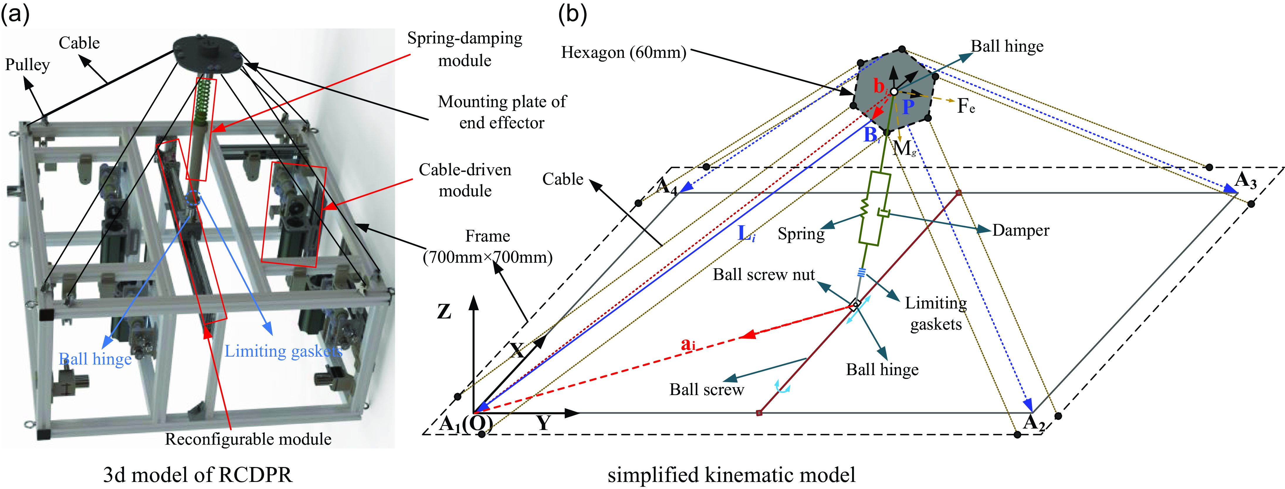
In summary, designing a CDPR that can be applied to large-space spraying, sorting, and assembly industries while achieving the same or superior work efficiency as the off-the-shelf CDPR is an interesting task. It is also required to meet the requirements of large workspace operation while optimizing and improving the CDPR motion stability and reducing the solution complexity and calculation amount of FFW. This paper proposes a reconfigurable cable-driven parallel robot (RCDPR), as shown in Figure 1. The principal contributions of this study are summarized as follows:
RCDPR.

-
1. This study designs a redundant reconfigurable cable-driven parallel robot and proposes a redundant drive scheme based on parallel cables and spring-damping module. The influence of configuration parameters, external force, and other structural constraints on the FFW is analyzed.
-
2. The boundary contour algorithm (BCA) of FFW based on numerical and boundary analytical methods is proposed, which significantly reduces the solution time while ensuring the solution accuracy of FFW.
-
3. The stability evaluation function is established with the FFW and main task feasible workspace (MFW) as the carrier and the stiffness and cables driving force space (CFS) as the weight. Through dimensional unification and Gaussian-weighted design, it can adapt to the global configuration optimization needs of CDPRs in different working conditions and has good application prospects for dynamic reconfiguration optimization.
This paper is organized as follows: Section 2 introduces the mechanical design and structural optimization analysis of RCDPR. Section 3 presents a detailed description of the FFW solution algorithm based on cable forces distribution and vector closure principle, and the verification results of the BCA for FFW. Section 4 establishes a stability evaluation function based on force-position workspace. The function of the proposed stability is composed of stiffness, maximum CFS, MFW and FFW. The Gaussian-weighted method is introduced to address each objective’s weight and magnitude differences. Section 5 presents the robot prototype and experiments performed for the RCDPR. The motion performance of the designed RCDPR is evaluated, and the feasibility of the FFW is verified. Finally, Section 6 concludes this paper.
2. Mechanical design
2.1. Transmission scheme
The three-dimensional model of the designed reconfigurable cable-driven parallel robot (RCDPR) is shown in Figure 1(a), which mainly consists of an end effector, spring-damping module, cable-driven module, and frame. The end effector achieves redundant driving through four parallel cables and spring-damping mechanisms. The global coordinate system O-XYZ is established with the position where the cables are connected to the frame as the base height and one corner of the frame as the center. The X and Y directions are parallel to the frame, and the Z axis direction is perpendicular to the XY plane and points to the end effector. A local coordinate system P-xyz is established at the center of the end effector, and its coordinate axis direction is the same as the direction of the global coordinate system. The parallel cables are controlled by the same motor, and a virtual connection between the midpoint of the two cables and the corresponding point on the end effector replaces the parallel cable. The simplified kinematic model of RCDPR is shown in Figure 1(b), where the simplified frame is a square, and the end effector is a rectangle.
RCDPR uses the magnetorheological damper as the rigid rod of the end effector and connects it to the end effector and the ball screw through a ball hinge. This dramatically simplifies the structural model of RCDPR and improves the positioning accuracy of RCDPR. When the RCDPR is working, the spring is always compressed, providing reaction force for the system to ensure that the cables are in a tensioned state and avoid virtual traction. The designed RCDPR’s end effector is driven by four sets of parallel cables, which limit its rotational freedom and further ensure the stability of its three translational motions. In addition, four sets of parallel cables drive the end effector redundantly to optimize the distribution of cable forces. This ensures the continuity of cable forces while increasing the workspace of the end effector. The magnetorheological damper is mounted on the ball screw as a rigid rod through a ball hinge to achieve the reconfiguration of the RCDPR. By adjusting the position of the ball screw nut, the stiffness of the RCDPR, the distribution of the workspace, and the cable forces can be adjusted. In addition, limiting gaskets adjust the position of the magnetorheological damper on the rigid rod, further ensuring RCDPR’s adaptability to complex and diverse operating environments.
The i th cable vector
 $\mathbf{L}_{i}$
can be obtained as
 \begin{equation} \mathbf{L}_{i} = \mathbf{a}_{i}-\mathbf{p}-{}_{\mathbf{P}}^{\mathbf{O}}{\mathbf{R}}{}\mathbf{b}_{i}\,\,i=1,2,\cdots ,m \end{equation}
Where
 $\mathbf{a}_{i}$
is the vector from the hinge to the global coordinate origin O.
 $\mathbf{b}_{i}$
is a vector from the center of the mounting plate to the cable exit point.
 ${}_{\mathbf{P}}^{\mathbf{O}}{\mathbf{R}}{}$
is the transformation matrix between the O-XYZ and the P-xyz. p is a vector from the hinge to the center of the mounting plate. m is the number of cables.
The length of cable
 $l_{i}$
can be expressed as
 \begin{equation} \mathbf{L}_{i}=-l_{i}\mathbf{u}_{i} \end{equation}
Where
 $\mathbf{u}_{\mathbf{i}}$
is the unit vector of the cable. Then,
 $l_{i}$
can be derived as
 \begin{equation} l_{i}=\sqrt{\left(-\mathbf{L}_{i}\mathbf{u}_{i}^{\mathrm{T}}\right)\left(-\mathbf{L}_{i}\mathbf{u}_{i}^{\mathrm{T}}\right)^{\mathrm{T}}}=\sqrt{\left(\mathbf{a}_{i}-\mathbf{p}-{}_{\mathbf{P}}^{\mathbf{O}}{\mathbf{R}}{}\mathbf{b}_{i}\right)\left(\mathbf{a}_{i}-\mathbf{p}- {}_{\mathbf{P}}^{\mathbf{O}}{\mathbf{R}}{}\mathbf{b}_{i}\right)^{\mathrm{T}}} \end{equation}
The cable unit vector
 $\mathbf{u}_{\mathbf{i}}$
can be expressed as
 \begin{equation} \mathbf{u}_{i}= -\frac{\mathbf{L}_{i}}{\left\| \mathbf{L}_{i}\right\| } \end{equation}
Simultaneous Eqs. (1) and (2), the velocity
 $\dot{l}_{i}$
of the cable can be established by taking the derivative of
 $\mathbf{L}_{\mathbf{i}}$
. Its mathematical expression is
 \begin{equation} d\left(\mathbf{L}_{i}\right)=d\left(\mathbf{a}_{i}-\mathbf{p}-{}_{\mathbf{P}}^{\mathbf{O}}{\mathbf{R}}{}\mathbf{b}_{i}\right)=-\dot{\mathbf{p}} \end{equation}
 \begin{equation} d\left(\mathbf{L}_{i}\right)=d\left(-l_{i}\mathbf{u}_{i}\right)=-l_{i}d\left(\mathbf{u}_{i}\right)-\dot{l}_{i}\mathbf{u}_{i}=-\mathbf{u}_{i}\dot{l}_{i} \end{equation}
 \begin{equation} \dot{l}_{i}=\mathbf{u}_{i}^{\mathrm{T}}\dot{\mathbf{p}} \end{equation}
The Jacobian matrix J can be expressed as
 \begin{equation} \mathbf{J}= \left[\begin{array}{llll} \mathbf{u}_{1} & \mathbf{u}_{2} & \cdots & \mathbf{u}_{m} \end{array}\right] \end{equation}
Then, the dynamic equation of the RCDPR end effector is derived
 \begin{equation} \mathbf{JT}+\hat{\mathbf{F}}_{E}+\hat{\mathbf{F}}_{I}=0 \end{equation}
Where
 $\hat{\mathbf{F}}_{E}$
and
 $\hat{\mathbf{F}}_{I}$
denote the torque and external force of both the end effector and the rigid rod. T is cables driving forces matrix. Since the rigid rod in RCDPR has a small mass, it is added to the end effector for simplicity and is not analyzed again.
 \begin{equation} \hat{\mathbf{F}}_{E}=\left[\begin{array}{l} \mathbf{W}\\[3pt] \hat{\mathbf{T}}_{E} \end{array}\right]=\left[\begin{array}{c} -\left(M\mathbf{g}\mathbf{+}\mathbf{F}_{e}\mathbf{+}\mathbf{F}_{s}+M\ddot{\mathbf{p}}\right)\\[3pt] 0 \end{array}\right] \end{equation}
Where W is the sum of the forces on the mounting plate.
 $\hat{\mathbf{T}}_{E}$
is the torque of the end effector and
 $\hat{\mathbf{T}}_{E}$
is zero since the end effector cannot rotate. M is the quality of the end effector, mounting plate and other components. F
e
is the external force acting on the end effector, including the reaction force of the operation process, etc.
 $\ddot{\mathbf{p}}$
is the acceleration vector of the mounting plate. g is the gravity vector. F
s
is the spring force vector.
The spring force
 $\| \mathbf{F}_{s}\|$
can be expressed as
 \begin{equation} \left\| \mathbf{F}_{s}\right\| =k_{s}\left(L_{msb}+L_{s}-l_{s}\right) \end{equation}
Where L s is the original length of the spring. L msb is the position of the spring. l s is the current length of the spring. k s is the stiffness of the spring.
2.2. Structural optimization analysis of RCDPR
The RCDPR developed in this paper will be applied to large-space spraying and has certain application prospects in other industries, such as sorting and assembly operations. The subsequent design and analysis of RCDPR will be based on the spraying operation. Therefore, the size of the mounting plate of the end effector depends on the size of the corresponding end effector, which further constrains the installation positions of the pulleys. Similarly, the size of the RCDPR frame needs to take into account the actual workspace and operating environment, so this paper does not optimize the size of the frame and the locations of the connection points between the cables and the mounting plate. It can be seen from the kinematics and dynamics equations of RCDPR that the parameters of the spring, the position of the spring, the position of the hinge and the external force have a significant impact on the forces of the cables. Due to the constraints of actual manufacturing conditions, we cannot obtain springs of arbitrary stiffness, length and material, and the external force is related to the actual working conditions and environment. Therefore, this paper mainly optimizes the spring position and hinge position of RCDPR, where the hinge position can be adjusted by a ball screw to achieve the reconfiguration of RCDPR. This can compensate for the constraints of external forces and springs to a certain extent. In addition, the workspace of the RCDPR can be reconfigured by adjusting the hinge position through the ball screw, which greatly improves the actual workspace of the RCDPR.
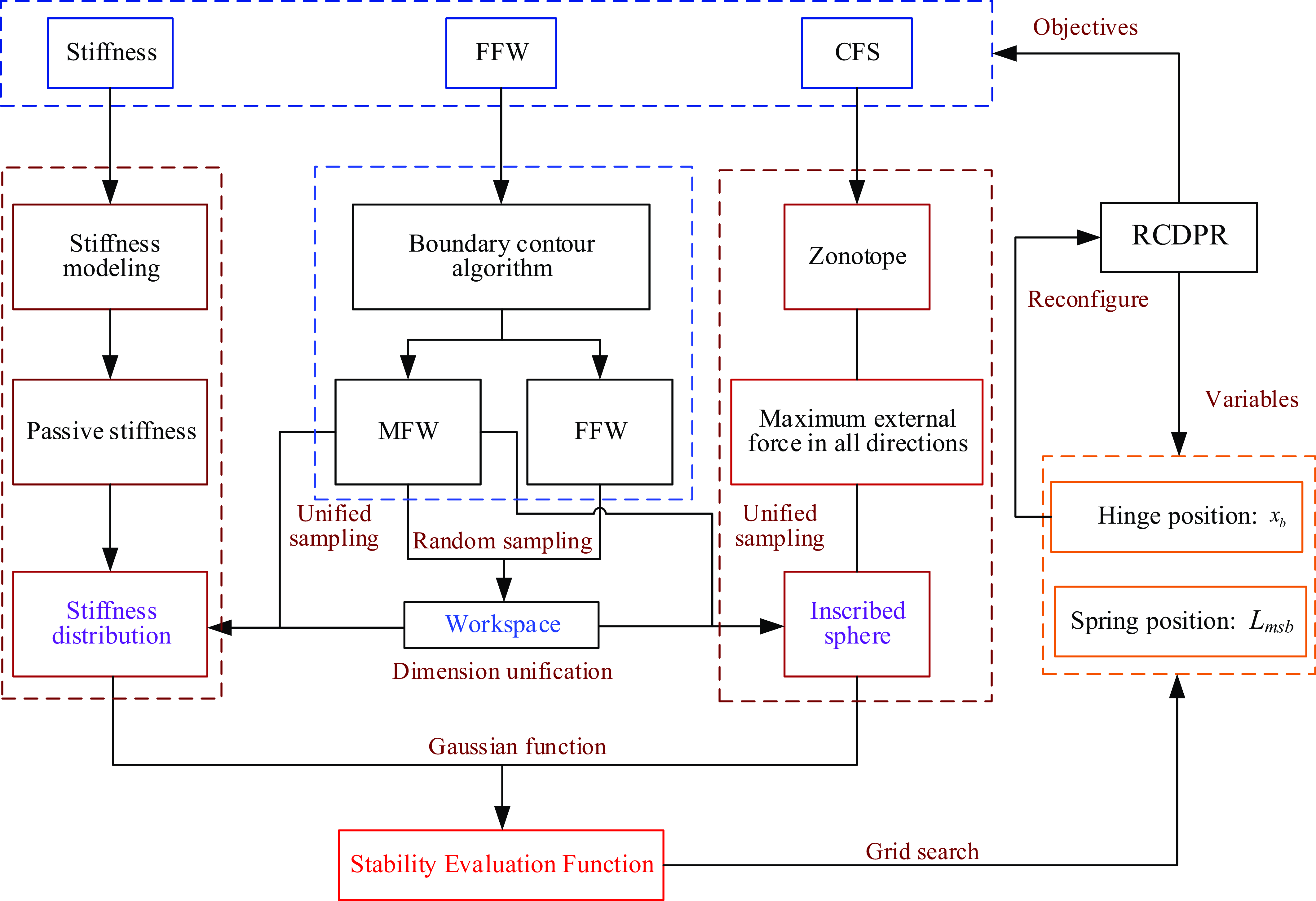
To optimize the spring position and hinge position of RCDPR, a stability modeling method based on force-position workspace is proposed in this paper, where the workspace, force, and position are represented by FFW, CFS, and stiffness of RCDPR, respectively. Then, a stability evaluation function is established with FFW as the carrier and stiffness and CFS as the weights. The design scheme of the stability evaluation function is shown in the Figure 2. Compared with the classical method, the designed stability evaluation function is not evaluated in isolation based on the size of a single indicator. This ensures the size of the RCDPR workspace while considering the RCDPR’s MFW and its mechanical performance parameters. In particular, the FFW and MFW are the main objectives of the stability evaluation function, and the accuracy and speed of the FFW solution greatly influence the effectiveness and practicality of the stability evaluation function. Therefore, it is necessary first to establish an accurate and fast calculation algorithm for the FFW of RCDPR.
Design of stability evaluation function.

3. Force feasible workspace solution of RCDPR
3.1. Optimization analysis of cable forces distribution
According to the RCDPR structure and the distribution of the four parallel cables, the dynamic equations have infinite solutions, and the number of unknowns is one more than the number of equations, that is, the dynamic equations have a one-dimensional null space basis. Based on Eq. (9), T can be derived as
 \begin{equation} \mathbf{T}= \mathbf{J}^{\oplus }\left(-\mathbf{W}\right)\mathbf{+}\mathbf{J}^{\boldsymbol{e}}\lambda \end{equation}
Where
 $\mathbf{J}^{\oplus }=\mathbf{J}^{\mathbf{T}}(\mathbf{J}\mathbf{J}^{\mathbf{T}})^{-\mathbf{1}}$
is the pseudo-inverse matrix of Jacobian matrix J,
 $\mathbf{J}^{\boldsymbol{e}}=N(\mathbf{J})$
is the null space basis of the Jacobian matrix J.
 $\lambda$
is a one-dimensional arbitrary scalar,
 $\lambda \in \mathbf{R}^{1}$
.
 \begin{equation} N\left(\mathbf{J}\right)=\left\{\mathbf{v}\in \mathbf{R}^{m}\colon \mathbf{Jv}=0\right\} \end{equation}
The FFW of RCDPR restrains the cable forces within a specific range,
 $T_{i}\in [\begin{array}{ll} T_{\min } & T_{\max } \end{array}]$
. Subsequently, Eq. (12) can be rewritten as
 \begin{equation} \mathbf{T}_{\min }-\mathbf{J}^{\oplus }\left(-\mathbf{W}\right)\leq N\left(\mathbf{J}\right)\lambda \leq \mathbf{T}_{\max }-\mathbf{J}^{\oplus }\left(-\mathbf{W}\right) \end{equation}
The one-dimensional arbitrary scalar
 $\lambda$
can be obtained as:
 \begin{equation} \lambda \in \left[\lambda _{\min },\,\,\lambda _{\max }\right] \end{equation}
In which
 \begin{equation} \begin{array}{l} \lambda _{\min }=\min\limits _{1\leq i\leq m}\left(\max\limits _{1\leq i\leq m}\left(\frac{T_{\min }-T_{i}}{N\left(\mathbf{J}\right)_{i}},\frac{T_{\max }-T_{i}}{N\left(\mathbf{J}\right)_{i}}\right)\right)\\[12pt] \lambda _{\max }=\max\limits _{1\leq i\leq m}\left(\min\limits _{1\leq i\leq m}\left(\frac{T_{\min }-T_{i}}{N\left(\mathbf{J}\right)_{i}},\frac{T_{\max }-T_{i}}{N\left(\mathbf{J}\right)_{i}}\right)\right) \end{array} \end{equation}
Where T
max and T
min are the maximum driving force and the minimum driving force of the cable respectively. T
max and T
min are corresponding vectors.
 $T_{i}=\mathbf{J}^{\oplus }(-\mathbf{W})_{i}$
is the force of the cable.
Further, the cable forces optimization model of the RCDPR can be expressed as:
 \begin{equation} \left\{\begin{array}{l} \min \,F\left(\lambda \right)\,\,\,\,\,\,\,\,\,\,\,\\[4pt] \begin{array}{l} \mathrm{s}.\mathrm{t}.\,\,\mathbf{JT}= -\mathbf{W}\,\\[4pt] \,\lambda \in \left[\lambda _{\min },\,\,\lambda _{\max }\right]\, \end{array} \end{array}\right. \end{equation}
Where
 $F(\lambda )$
is the cable forces optimization function.
RCDPR has a variety of cable forces distribution optimization algorithms (FDA), including the P-norm method, minimum variance method, and centroid method. Because the cable forces solution set of RCDPR is a convex hull, the feasible domain of Eq. (17) is also a convex set. When the objective function F is a convex function, the cable forces solution problem becomes a convex optimization problem. From the optimization theory, we know that any local optimal solution of the convex optimization problem is the global optimal solution, and the optimal solution of the cable forces can be obtained. Based on real-time performance and smoothness, the P-norm method is selected for numerical simulation. When P ≥ 1, force distribution optimization will be a convex optimization problem. The larger the P value of the norm method, the better the flexibility of force distribution control, but the greater the amount of calculation. Therefore, this paper will establish the evaluation indicators
 $\Delta T$
and
 $\nabla T$
to select the appropriate P-norm. When
 $F(\lambda )$
adopts the P-norm, it can be written as follows:
 \begin{equation} F\left(\lambda \right)=\min \left(T_{1}^{P_{n}}+T_{2}^{P_{n}}+\cdots +T_{m}^{P_{n}}\right)^{\frac{1}{P_{n}}}P_{n}\geq 1 \end{equation}
Where
 $P_{n}$
is the P value of the P-norm.
Let
 $f(\lambda )=T_{1}^{P_{n}}+T_{2}^{P_{n}}+\cdots +T_{m}^{P_{n}}$
, then
 $f(\lambda )$
can be organized into a
 $P_{n}$
-order polynomial concerning
 $\lambda$
.
 \begin{equation} f\left(\lambda \right)=A_{{p_{n}}+1}\lambda ^{{p_{n}}}+A_{{p_{n}}}\lambda ^{{p_{n}}-1}+\cdots +A_{2}\lambda +A_{1} \end{equation}
Where A
i
are the coefficients of
 $f(\lambda )$
. Solve for the stationary point about
 $f(\lambda )$
to calculate the optimal solution
 $\lambda$
. The mathematical expressions of
 $\Delta T$
and
 $\nabla T$
are:
 \begin{equation} \Delta T=\left\| \mathbf{T}_{i+1}-\mathbf{T}_{i}\right\| \nabla T=\max \left\| \frac{\mathbf{T}_{i+1}-\mathbf{T}_{i}}{\Delta t}-\frac{\mathbf{T}_{i}-\mathbf{T}_{i-1}}{\Delta t}\right\| \end{equation}
Where
 $\Delta t$
is the control period.
 $\Delta T$
is the cable driving force increment.
 $\nabla T$
is the driving force time increment.
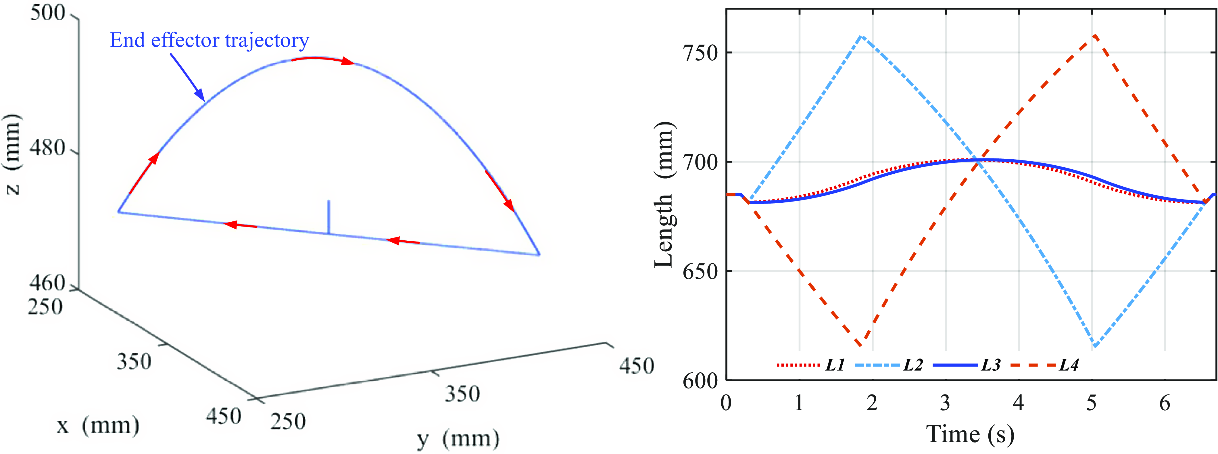
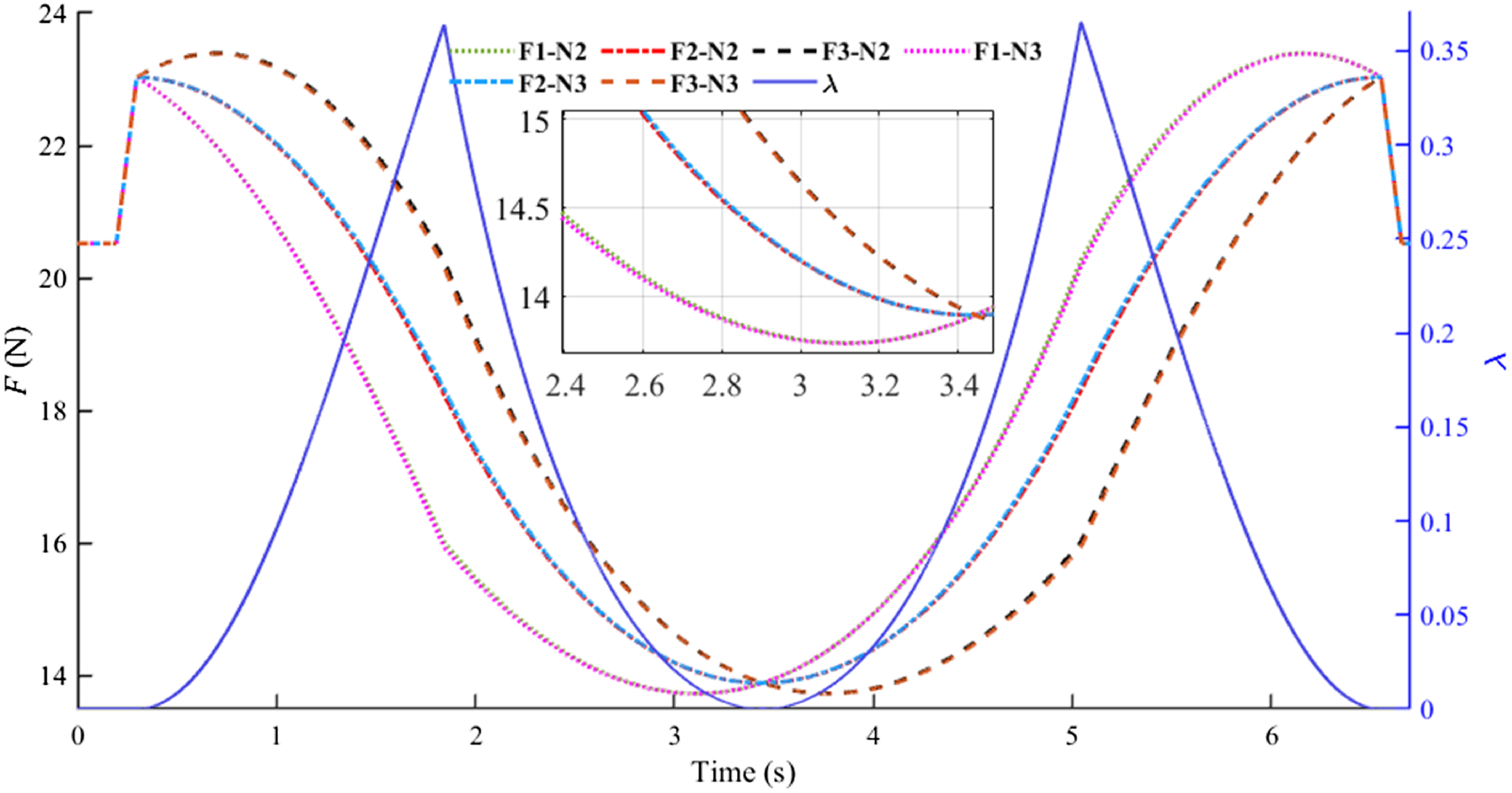
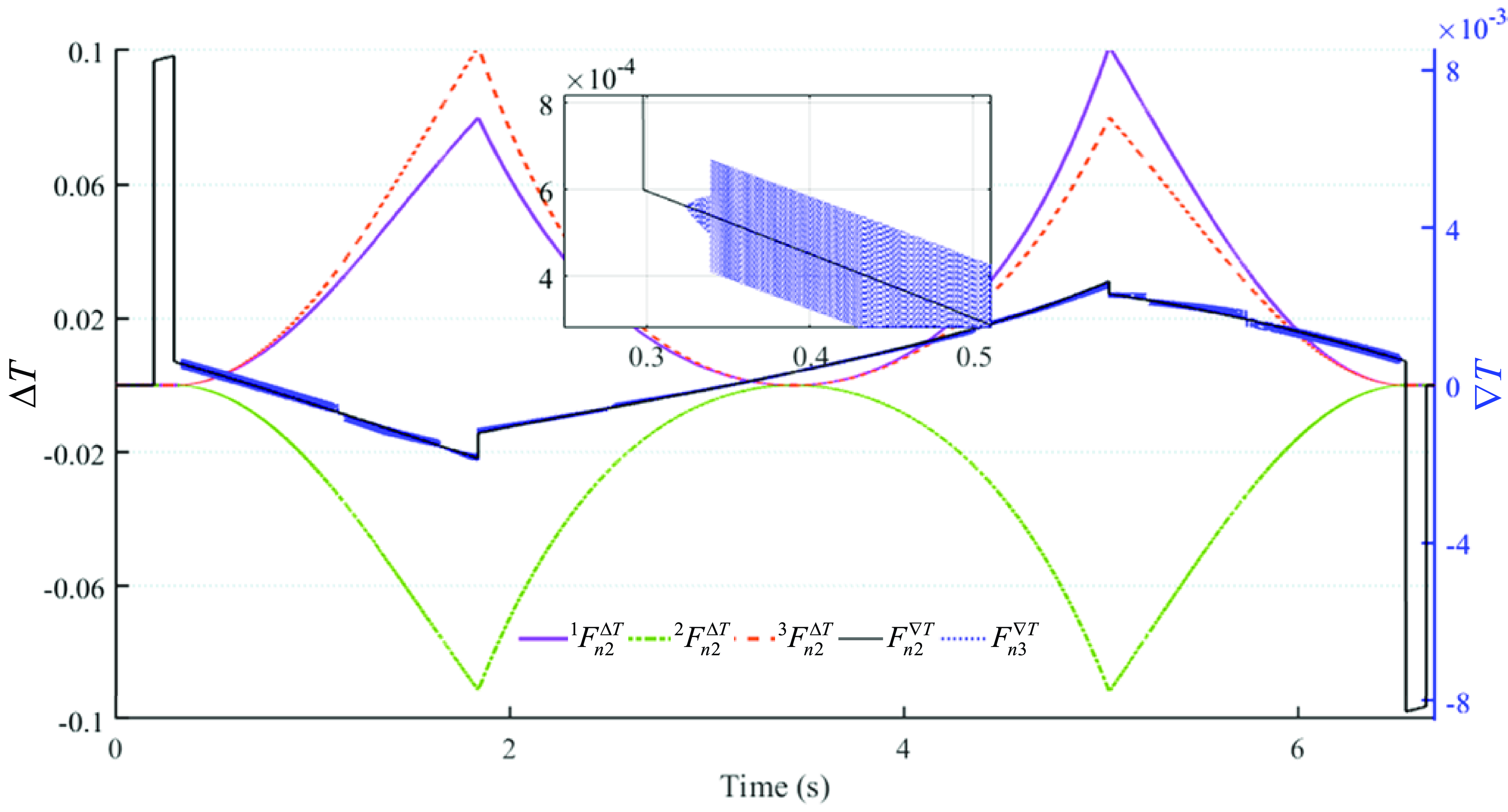
Figure3 shows the spatial arc trajectory of the end effector and the length changes of the four cables. This paper uses the minimum 2-norm and the minimum 3-norm to solve the cable forces distribution, as shown in Figures4 and5. The cable forces transition of the two algorithms is smooth, the maximum amplitude of
 $\Delta T$
does not exceed 0.1 N, and the cable forces are relatively similar. The calculation time of the minimum 2-norm is much lower than that of the minimum 3-norm.
 $\lambda$
under the 3-norm has a certain regulating effect on the cable force, but due to the limitation of the RCDPR structure,
 $\lambda$
is always zero under specific trajectories. The cable driving force increment
 $\Delta T$
of the minimum 2-norm and the minimum 3-norm is similar. However, the minimum 2-norm changes in the driving force time increment
 $\nabla T$
more continuously, with a smaller fluctuation amplitude. Therefore, the minimum 2-norm has specific guiding significance for the optimization of driving forces distribution.
The spatial arc trajectory of the end effector and the lengths of the four cables.

Cable forces distribution with 2-norm and 3-norm (Fi-N2 are the cable forces with 2-norm, Fi-N3 are the cable forces with 3-norm).

 $\Delta T$
and
 $\nabla T$
with 2-norm and 3-norm (
 ${}^{1}F_{n2}^{\Delta T}$
,
 ${}^{2}F_{n2}^{\Delta T}$
,
 ${}^{3}F_{n2}^{\Delta T}$
is the
 $\Delta T$
with 2-norm,
 $F_{n2}^{\nabla T}$
is the
 $\nabla T$
with 2-norm,
 $F_{n3}^{\nabla T}$
is the
 $\nabla T$
with 3-norm).

3.2. Force feasible workspace of RCDPR
The solution of the force distribution optimization algorithm (FDA) of redundant RCDPR is more complicated than that of fully constrained CDPR. In addition to FDA, the principle of convex sets and vector closure algorithm (PSA) has significant advantages in the calculation of FFW [Reference Rasheed, Long and Marquez-Gamez18]. The solution process of the FDA is to calculate the minimum and maximum cable forces based on the cable force constraint range. 2-norm (Eq. (17)) is used to optimize the cable forces distribution, perform linear programming on λ based on the one-dimensional constraint space, and determine whether the cable forces satisfy the constraint. FDA determines whether the cable forces meet the constraint conditions by solving parameter λ, which requires linear programming of the parameters λ and a large amount of calculation. In addition, since the solution of the cable forces depends on the FDA’s model, the calculated FFW is only a subset of the actual FFW.
The principle of PSA to solve FFW is based on the principle of vector closure. Given the end effector position P.
 \begin{equation} \forall \mathbf{W}\in \mathbf{R}^{n} \quad \exists T_{1},T_{2}, \cdots , T_{m}\in \left[0,\infty \right),\,\,\sum _{i=1}^{m}T_{i}\mathbf{J}_{i}=-\mathbf{W} \end{equation}
Then the position P belongs to the force closure workspace. n is the degree of freedom of the end effector. Further, Eq. (21) can be transformed into:
 \begin{equation} \sum\limits _{i=1}^{m}\frac{T_{i}}{\sum\limits _{i=1}^{m}T_{i}+1}\mathbf{J}_{i}+\frac{1}{\sum\limits _{i=1}^{m}T_{i}+1}\mathbf{W}= \mathbf{0} \end{equation}
Subsequently, Eq. (22) can be rewritten as
 \begin{equation} \sum\limits _{i=1}^{m+1}\alpha _{i}q_{i}^{J}=0 \end{equation}
In which
 \begin{equation} \alpha _{i}=\frac{T_{i}}{\sum\limits _{i=1}^{m}T_{i}+1}\left(i=1\sim m\right), \enspace \enspace \enspace \enspace \enspace \enspace \enspace \enspace \alpha _{m+1}=\frac{T_{i}}{\sum\limits _{i=1}^{m}T_{i}+1} \end{equation}
 \begin{equation} q_{i}^{J}=\mathbf{J}_{i},\,\,\,q_{i+1}^{J}=\mathbf{W} \end{equation}
Therefore, all the end effector position P in the force closure workspace satisfy the definition of the convex hull. The convex hull P c can be expressed as
 \begin{equation} co\left(\mathbf{P}^{\mathbf{c}}\right)\colon \left\{P=\sum\limits _{i}^{m+1}\alpha _{i}q_{i}^{J}\colon \sum\limits _{i}^{m+1}\alpha _{i}=1,\alpha _{i}\geq 0,\left(i=1,\cdots ,m+1\right)\right\} \end{equation}
Furthermore, based on the research of Liu et al. [Reference Liu, Qiu and Sheng42], for the fully constrained CDRR (m≥n + 1), the FFW of CDPRs is the set of end effector position P that satisfies the following relationship
 \begin{eqnarray} &&\def\lumina\hspace*{-10pt} \left\{P\;\colon rank\left(\mathbf{J}\right) = n\cap \forall \overline{\mathbf{J}}\in \mathbf{R}^{n}\,\,\overline{\mathbf{J}}^{T}\left(-\mathbf{W}\right)\gt 0\right.\exists \hat{\mathbf{J}}_{a}\;\colon \left.\overline{\mathbf{J}}\hat{\mathbf{J}}_{a}\lt 0\cap \Upsilon_{\min }^{-}\leq \Upsilon_{\max }^{+}+\overline{\mathbf{J}}\left(-\mathbf{W}\right)\cap \Upsilon_{\min }^{+} \right. \nonumber\\ && \quad \left. +\, \overline{\mathbf{J}}\left(-\mathbf{W}\right)\leq \Upsilon_{\max }^{-}\right\}\cup \nonumber\\ &&\def\lumina\hspace*{-10pt} \left\{P\;\colon rank\left(\mathbf{J}\right)=n\cap \forall \overline{\mathbf{J}}\in \mathbf{R}^{n}\,\,\overline{\mathbf{J}}^{T}\left(-\mathbf{W}\right)=0\right.\exists \hat{\mathbf{J}}_{a},\hat{\mathbf{J}}_{b}\;\colon \left.\overline{\mathbf{J}}\hat{\mathbf{J}}_{a}\gt 0\cap \overline{\mathbf{J}}\hat{\mathbf{J}}_{b}\lt 0\cap \Upsilon_{\min }^{-}\leq \Upsilon_{\max }^{+}\cap \Upsilon_{\min }^{+}\leq \Upsilon_{\max }^{-}\right\}\cup \nonumber\\ &&\def\lumina\hspace*{-10pt} \left\{P\;\colon rank\left(\mathbf{J}\right) = n\cap \forall \overline{\mathbf{J}}\in \mathbf{R}^{n}\,\,\overline{\mathbf{J}}^{T}\left(-\mathbf{W}\right)\lt 0\right.\exists \hat{\mathbf{J}}_{b}\;\colon \left.\overline{\mathbf{J}}\hat{\mathbf{J}}_{b}\gt 0\cap \Upsilon_{\min }^{-}\leq \Upsilon_{\max }^{+}+\overline{\mathbf{J}}\left(-\mathbf{W}\right)\cap \Upsilon_{\min }^{+} \right. \nonumber\\ && \quad \left. +\, \overline{\mathbf{J}}\left(-\mathbf{W}\right)\leq \Upsilon_{\max }^{-}\right\} \end{eqnarray}
In which
 \begin{equation} \begin{array}{l} \Upsilon_{\min }^{-}=\sum\limits _{\overline{\mathbf{J}}\hat{\mathbf{J}}_{a}\lt 0}\left| \overline{\mathbf{J}}\hat{\mathbf{J}}_{a}\right| T_{\min },\,\,\,\Upsilon_{\max }^{-}=\sum\limits _{\overline{\mathbf{J}}\hat{\mathbf{J}}_{a}\lt 0}\left| \overline{\mathbf{J}}\hat{\mathbf{J}}_{a}\right| T_{\max }\\[10pt] \Upsilon_{\min }^{+}=\sum\limits _{\overline{\mathbf{J}}\hat{\mathbf{J}}_{b}\gt 0}\left| \overline{\mathbf{J}}\hat{\mathbf{J}}_{b}\right| T_{\min },\,\,\,\Upsilon_{\max }^{+}=\sum\limits _{\overline{\mathbf{J}}\hat{\mathbf{J}}_{b}\gt 0}\left| \overline{\mathbf{J}}\hat{\mathbf{J}}_{b}\right| T_{\max } \end{array} \end{equation}
Where
 $\overline{\mathbf{J}}$
is any n-1 linearly independent vector in J.
 $\hat{\mathbf{J}}_{a} , \hat{\mathbf{J}}_{b}$
is the remaining vector after removing
 $\overline{\mathbf{J}}$
from J.
Based on convex hull analysis (Eq. (26)), in the frame space of the RCDPR developed in this paper, all position points belong to the force closure workspace. Removing the constraint of force closure workspace in equation Eq. (27), it can be rewritten as
 \begin{equation} P_{F}\;\colon \left\{\Upsilon_{\max }^{+}+\overline{\mathbf{J}}\left(-\mathbf{W}\right)-\Upsilon_{\min }^{-}\geq 0\cap \Upsilon_{\max }^{-}-\overline{\mathbf{J}}\left(-\mathbf{W}\right)-\Upsilon_{\min }^{-}\geq 0\right\} \end{equation}
Where
 $P_{F}$
is the end effector position in the FFW.
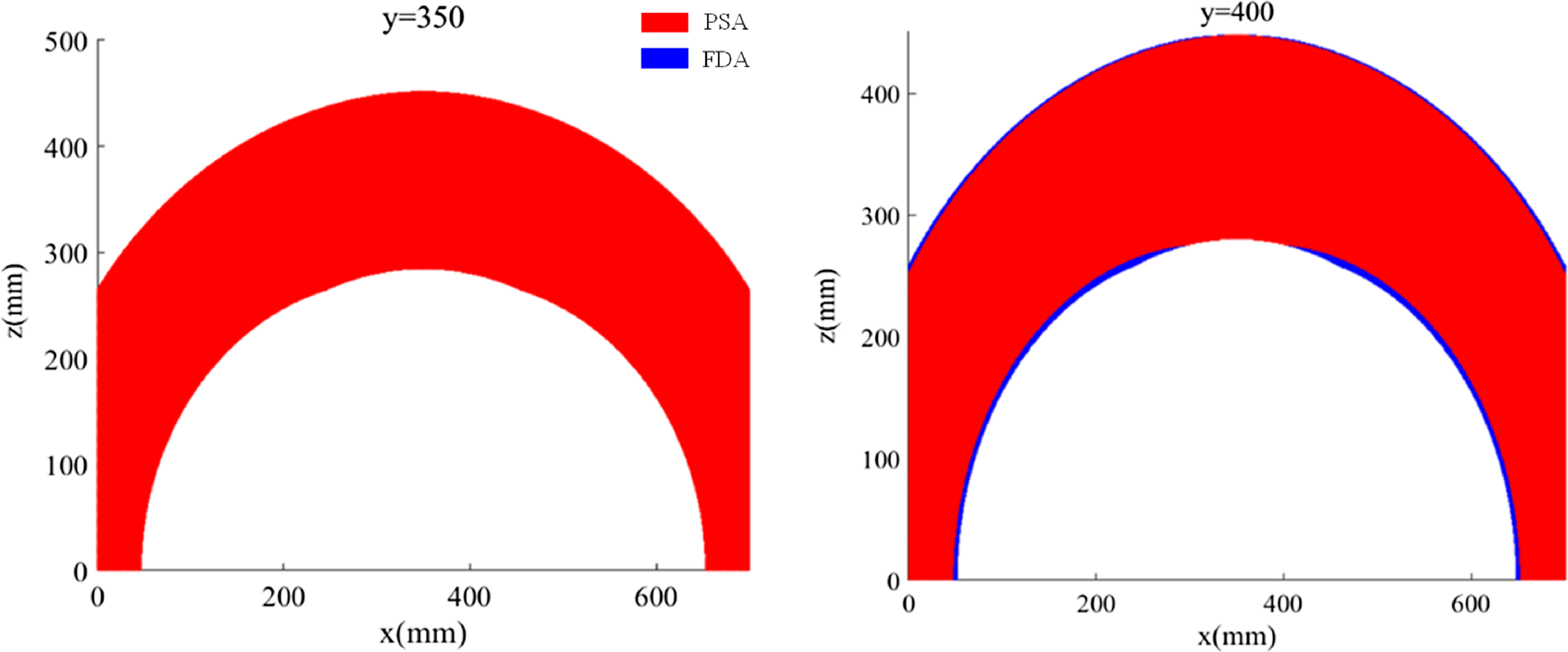
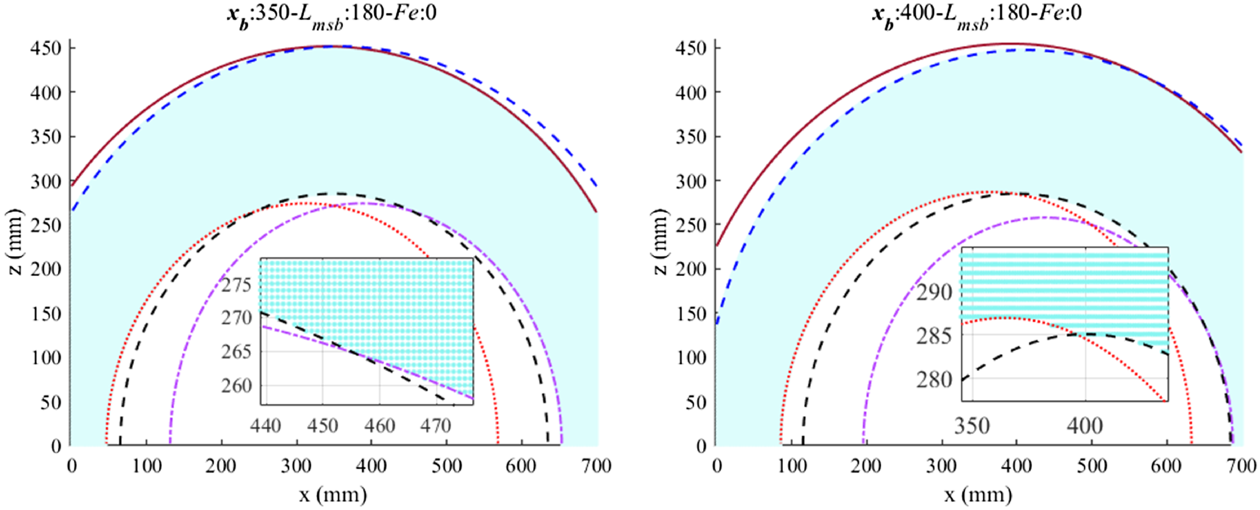
The solutions of both PSA and FDA require discretizing the workspace and scanning point by point. The solution accuracy and time depend on the scanning step size. Figure 6 shows the exhaustive search of the workspace through the PSA and FDA methods, the FFW at the y = 350 mm and y = 400 mm planes, and the step size is 1 mm. As shown in Figure 6, the solution results of the two algorithms are completely consistent in the central plane y = 350 mm. At the y = 400 mm plane, the FDA’s FFW is a subset of PSA’s. The main reason is that the 2-norm optimization algorithm discards some edge or unstable solutions.
FFW of the RCDPR.

3.3. Boundary contour algorithm for FFW
The designed boundary contour algorithm (BCA) is also based on the forces distribution algorithm (2-norm) and has the same results as the FDA. As shown in Figure 6, numerical simulation verifies the higher solution accuracy of PSA and FDA on the FFW of RCDPR, which is approximately an ellipsoid. However, in practical applications, the maximum compression amount of the spring, the configuration of the RCDPR, and the maximum deflection angle of the ball hinge will further constrain the FFW, as shown in Figure 6. This section will design the BCA solution process of RCDPR’s FFW on the center plane based on the 2-norm forces distribution optimization (
 $\lambda \equiv 0$
). The designed BCA uses the hinge position and spring position as design parameters to optimize the structure of the RCDPR. By solving the FFW of RCDPR, it is found that the shape of FFW is similar to a body of rotation around the x-axis. In order to further simplify the calculation amount of FFW, this paper subsequently uses the area
 $S_{\Theta }$
of FFW at the central plane (y = 350 mm) to represent all FFW of RCDPR.
According to the dynamic equation Eq. (12) of RCDPR, the boundary equation
 $\Gamma _{l}^{u}$
of the cable-constrained FFW can be expressed as
 \begin{equation} \Gamma _{l}^{u}\left(x,z\right)= \mathbf{J}^{\mathbf{T}}\left(\mathbf{J}\mathbf{J}^{\mathbf{T}}\right)^{-\mathbf{1}}\left(-\mathbf{W}\right)-\mathbf{T}_{\max }^{\min } \end{equation}
Where
 $\mathbf{T}_{\max }^{\min }$
matrix format of the upper and lower boundaries of cable force. In the FFW of the central plane, the forces of cables 1 and 4 (2 and 3) are equal. Taking cable-1 and cable-2 as the research subjects, establish the lower and upper boundary equations
 $\Gamma _{l}^{1} ,\ \Gamma _{l}^{2} ,\ \Gamma _{u}^{1}$
, and
 $\Gamma _{u}^{2}$
of the cables, respectively.
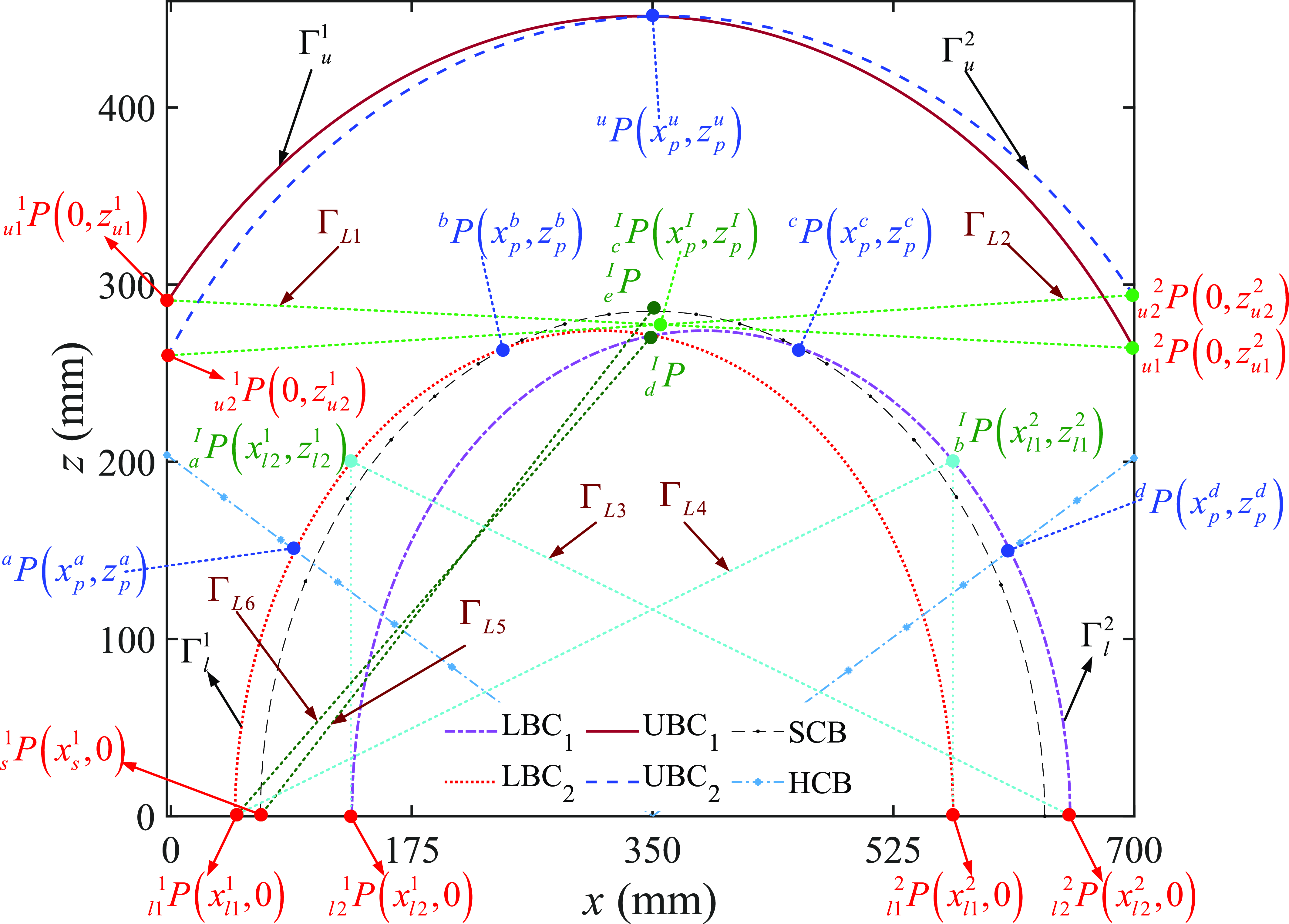
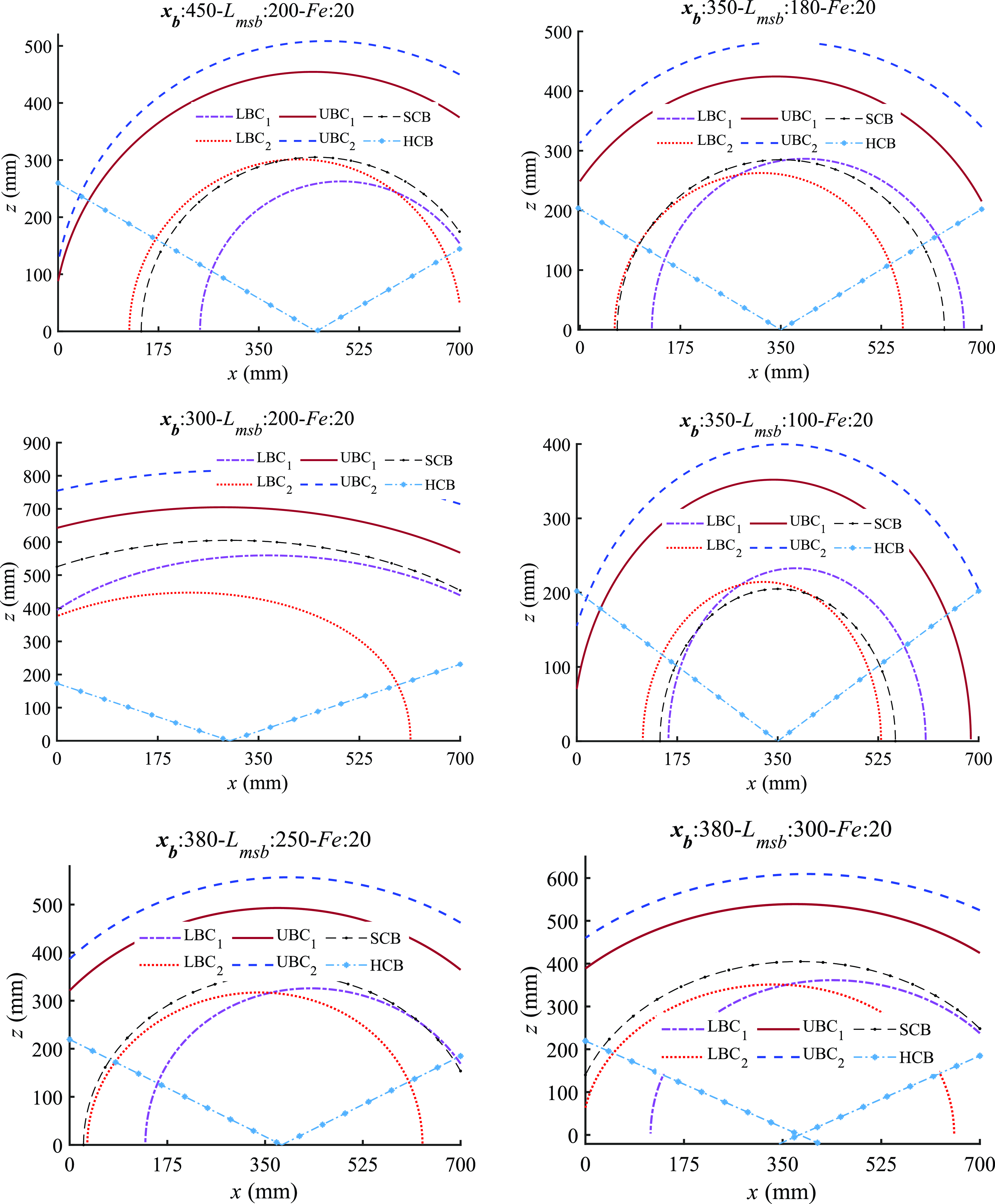
As shown in Figure 7, UBC1 and UBC2 are, respectively, the FFW boundary groups
 $\Gamma _{u}^{1}$
and
 $\Gamma _{u}^{2}$
, determined by the lower limit of the cable forces. LBC1 and LBC2 are, respectively, the FFW boundary groups
 $\Gamma _{l}^{1}$
and
 $\Gamma _{l}^{2}$
, determined by the upper limit of the cable forces. SCB is the boundary equation
 $\Gamma _{S}$
, constrained by the maximum compression of the spring, and HCB is the boundary equation
 $\Gamma _{H}$
, constrained by the ball hinge.
Boundary contour of FFW.

 \begin{equation} \begin{array}{l} \left\{\begin{array}{ll} \Gamma _{u}^{1}\left(x,z\right) & \Gamma _{u}^{2}\left(x,z\right) \end{array}\right\}\colon \mathbf{J}^{\mathbf{T}}\left(\mathbf{J}\mathbf{J}^{\mathbf{T}}\right)^{-\mathbf{1}}\left(-\mathbf{W}\right)-T_{\min }=0\\[10pt] \left\{\begin{array}{ll} \Gamma _{l}^{1}\left(x,z\right) & \Gamma _{l}^{2}\left(x,z\right) \end{array}\right\}\colon \mathbf{J}^{\mathbf{T}}\left(\mathbf{J}\mathbf{J}^{\mathbf{T}}\right)^{-\mathbf{1}}\left(-\mathbf{W}\right)-T_{\max }=0 \end{array} \end{equation}
 $\Gamma _{l}^{u}$
is an equation containing a transcendental function, and it is not easy to obtain an analytical solution. Newton’s method is used to solve it. However, the form of
 $\Gamma _{l}^{u}$
is relatively complex and has multiple solutions. In the numerical solution process using Newton’s method, iterations often fail to converge, or there are too many iterations, causing the program to fall into an infinite loop or fail to obtain an accurate solution. This takes up a lot of computing power and consumes much computing time.
As shown in Figure 7, the boundary contour of FFW is composed of multiple sets of equations. In order to ensure the calculation accuracy of calculating
 $S_{\Theta }$
, it is necessary to accurately solve the intersection point of the corresponding boundary contour, and the cable boundary equations
 $\Gamma _{u}^{1} , \Gamma _{u}^{2} , \Gamma _{l}^{1}$
and
 $\Gamma _{l}^{2}$
need to be solved simultaneously. However, there are usually situations where there are multiple solutions or no solutions, making it impossible to obtain the exact solution required or causing the program to fall into an infinite loop due to non-convergence. It seriously affects the solution time and solution accuracy of
 $S_{\Theta }$
. In response to this phenomenon, this paper designs an auxiliary linear equation method to optimize the accuracy and solution time of the intersection point of the boundary contour.
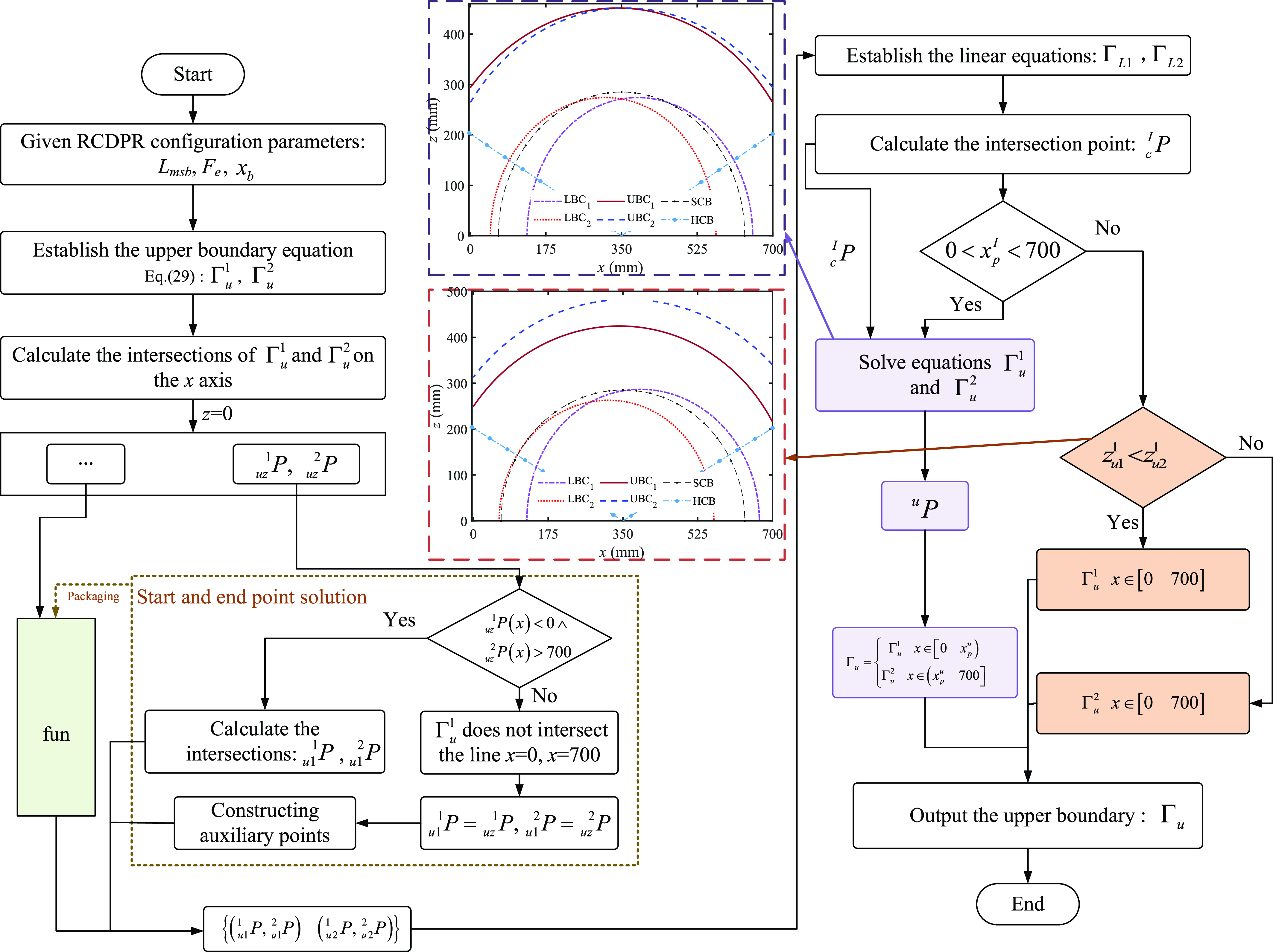
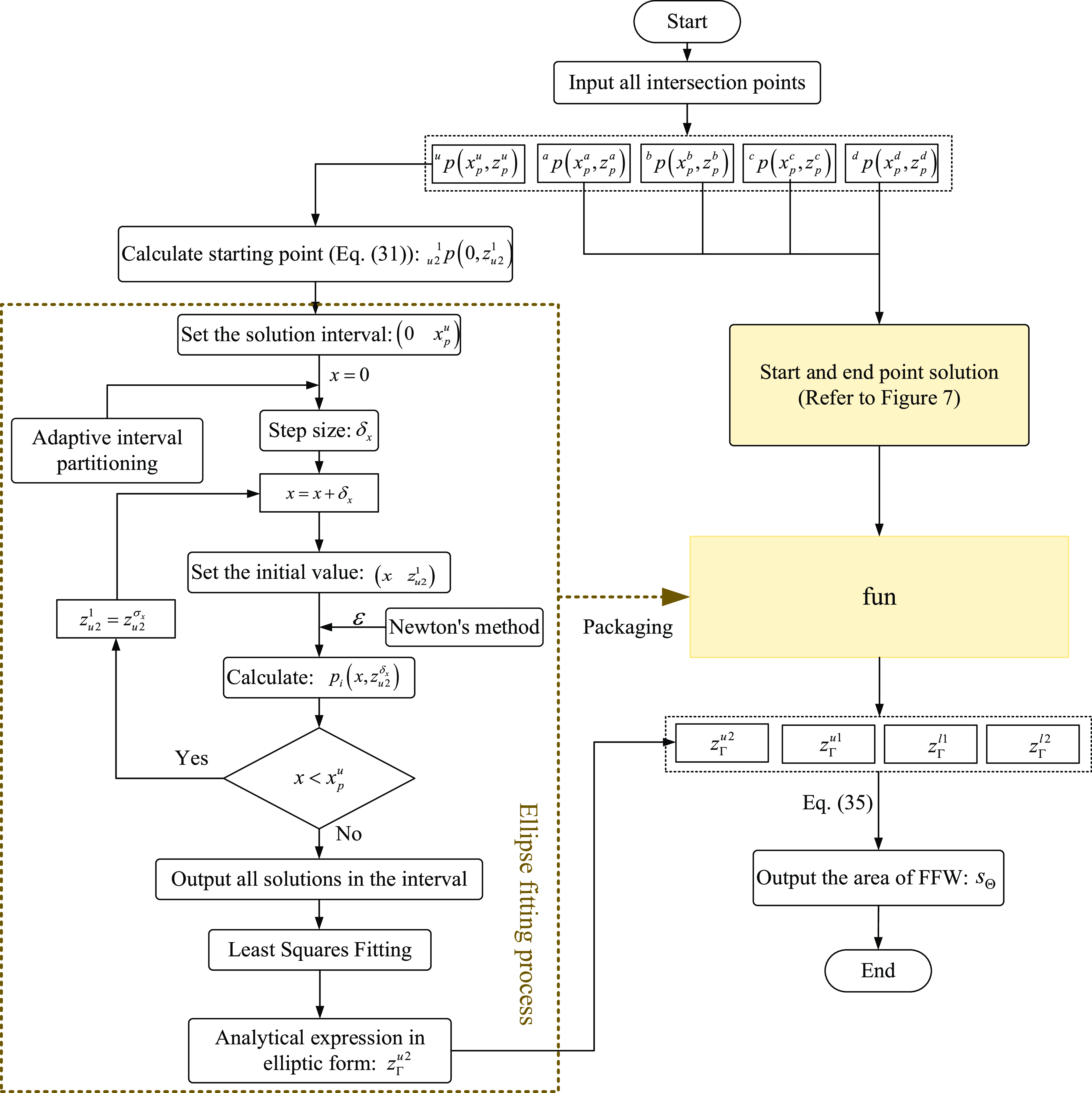
The boundary contour distribution of FFW of RCDPR under different structural parameters is quite different. In order to explain the boundary contour solution process of FFW more clearly, this paper will take the common FFW as an example (as shown in Figure 7). The flowchart for solving the upper boundary contour is shown in Figure 8, which only shows the solution process of the upper boundary contour of the configuration in Figure 7.
Flowchart for solving the upper boundary contour.

The specific solution process is as follows: First, calculate the intersection points
 $_{uz}^{1}P$
and
 $_{uz}^{2}P$
of
 $\Gamma _{u}^{1}$
at z = 0. If the abscissas
 $_{uz}^{1}P(x)$
and
 $_{uz}^{2}P(x)$
of intersection points are less than 0 and greater than 700, respectively, then calculate the intersection points
 $_{u1}^{1}P$
and
 $_{u1}^{2}P$
of
 $\Gamma _{u}^{1}$
at x = 0 and x = 700. If the abscissas of its intersection points are within (0–700), that is,
 $\Gamma _{u}^{1}$
has no solution at x = 0 and x = 700, then the
 $_{uz}^{1}P$
and
 $_{uz}^{2}P$
points are regarded as
 $_{u1}^{1}P$
and
 $_{u1}^{2}P$
, which are also the start and end points of the upper boundary contour.
 $\Gamma _{u}^{2} , \Gamma _{l}^{1}$
and
 $\Gamma _{l}^{2}$
all use this algorithm to solve the starting and ending points. Finally, two linear equations
 $\Gamma _{L1}$
and
 $\Gamma _{L2}$
composed of
 $(_{u1}^{1}P,\,\,_{u1}^{2}P)$
and
 $(_{u2}^{1}P,\ _{u2}^{2}P)$
, are respectively established to solve the intersection point
 $_{c}^{I}P$
of
 $\Gamma _{L1}$
and
 $\Gamma _{L2}$
. If
 $x_{p}^{I}\in (\begin{array}{ll} 0\,\,700 \end{array})$
, there is an intersection between
 $\Gamma _{L1}$
and
 $\Gamma _{L2}$
, then use
 $_{c}^{I}P$
as the initial value to enter the simultaneous equations of
 $\Gamma _{u}^{1}$
and
 $\Gamma _{u}^{2}$
to solve the intersection point
 ${}^{u}{P}{}$
. Otherwise, there is no intersection between
 $\Gamma _{u}^{1}$
and
 $\Gamma _{u}^{2}$
. We can determine which of
 $\Gamma _{u}^{1}$
and
 $\Gamma _{u}^{2}$
is the upper boundary contour equation by the size of the ordinates of
 $_{u1}^{1}P$
and
 $_{u2}^{1}P$
.
The intersection process of
 $\Gamma _{l}^{1}$
and
 $\Gamma _{l}^{2}$
is similar to the solution of the intersection of
 $\Gamma _{u}^{1}$
and
 $\Gamma _{u}^{2}$
. If the abscissas of
 $_{l1}^{1}P ,\ _{l2}^{1}P ,\ _{l1}^{2}P$
and
 $_{l2}^{2}P$
at the intersection of
 $\Gamma _{l}^{1}$
and
 $\Gamma _{l}^{2}$
at y=0 are in the interval (0, 700), the boundary contours of
 $\Gamma _{l}^{1}$
and
 $\Gamma _{l}^{2}$
are both within the frame. Then solve the coordinates of auxiliary points
 $_{a}^{I}P$
and
 $_{b}^{I}P$
on
 $\Gamma _{l}^{1}$
and
 $\Gamma _{l}^{2}$
using the abscissas of
 $_{l2}^{1}P$
and
 $_{l1}^{2}P$
, respectively. Finally, establish
 $\Gamma _{L3}$
and
 $\Gamma _{L4}$
through the points
 $(_{l1}^{1}P,\ _{b}^{I}P)$
and
 $(_{a}^{I}P,\ _{l2}^{1}P)$
, determine whether there is an intersection between
 $\Gamma _{l}^{1}$
and
 $\Gamma _{l}^{2}$
, and solve for the intersection
 $_{d}^{I}P$
.
Next, solve the intersection point of
 $\Gamma _{l}^{1}$
and
 $\Gamma _{S}$
. First, solve the coordinate points
 $_{e}^{I}P$
and
 $_{s}^{I}P$
on
 $\Gamma _{S}$
through the abscissa coordinate of
 $_{d}^{I}P$
, and then establish the linear equations
 $\Gamma _{L5}$
and
 $\Gamma _{L6}$
through
 $({l1}^{1}{P}{},\,\,{d}^{I}{P}{})$
and
 $({s}^{I}{P}{},\,\,{e}^{I}{P}{})$
. Furthermore, similarly, the intersection of
 $\Gamma _{L5}$
and
 $\Gamma _{L6}$
is used to determine whether
 $\Gamma _{l}^{1}$
and
 $\Gamma _{S}$
intersect, and solve for the intersection point
 ${}^{b}{P}{}$
. It is relatively easy to solve the intersections of
 $\Gamma _{H}^{1}$
and
 $\Gamma _{l}^{1}$
. In addition, the other boundary intersections can also be solved by the above method and will not be described again.
Then, the area
 $S_{\Theta }$
of FFW can be expressed as
 \begin{equation} S_{\Theta }=\int _{0}^{x_{p}^{u}}\Gamma _{u}^{2}dx+\int _{x_{p}^{u}}^{700}\Gamma _{u}^{1}dx-\int _{0}^{x_{p}^{a}}\Gamma _{H}^{1}dx-\int _{x_{p}^{a}}^{x_{p}^{b}}\Gamma _{l}^{1}dx-\int _{x_{p}^{b}}^{x_{p}^{c}}\Gamma _{S}dx-\int _{x_{p}^{c}}^{x_{p}^{d}}\Gamma _{l}^{2}dx-\int _{x_{p}^{d}}^{700}\Gamma _{H}^{2}dx \end{equation}
Where
 $\Gamma _{H}^{1}$
and
 $\Gamma _{H}^{2}$
are the constraint equations on both sides of the spherical hinge, respectively.
 $x_{p}^{u} ,\ x_{p}^{a} ,\ x_{p}^{b} ,\ x_{p}^{c}$
, and
 $x_{p}^{d}$
are the abscissa of the corresponding boundary contour intersection points
 ${}^{u}{P}{} ,\ {}^{a}{P}{} ,\ {}^{b}{P}{} ,\ {}^{c}{P}{}$
, and
 ${}^{d}{P}{}$
, respectively.
In order to meet the stability optimization and dynamic reconfiguration requirements of RCDPR, it is necessary to simplify the solution process and mathematical expression of
 $\Gamma _{l}^{u}$
. In addition,
 $\Gamma _{l}^{u}$
is an implicit function about x and z, and
 $S_{\Theta }$
cannot be solved by direct integration. Therefore, this paper solves all the solutions of
 $\Gamma _{l}^{u}$
within the frame (0–700 mm) and uses elliptic equations for fitting to meet the
 $S_{\Theta }$
solution accuracy. The flowchart for solving area
 $S_{\Theta }$
of FFW is shown in Figure 9.
Flowchart for solving area
 $S_{\Theta }$
of FFW.

Next, taking
 $\Gamma _{u}^{2}$
as an example, the solution method is as follows. First solve the intersection point
 $ _{u2}^{\,\,1}{P}{}(0,z_{u2}^{1})$
between
 $\Gamma _{u}^{2}$
and the x-axis or z-axis
 \begin{equation} \Gamma _{u}^{2}\left({u2}^{1}{P}{}\right)\colon \mathbf{J}^{\mathbf{T}}\left(\mathbf{J}\mathbf{J}^{\mathbf{T}}\right)^{-\mathbf{1}}\left(-\mathbf{W}\right)-T_{\min }=0 \quad x=0 \end{equation}
Then, using
 $z_{u2}^{1}$
as the initial value and
 $\delta _{x}$
as the step size, calculate the solution of
 $P_{i}(x,z_{u2}^{\delta _{x}})$
where
 $x=\delta _{x}$
. Furthermore, the error standard
 $\varepsilon$
is set, and
 $P_{i}(x,z_{u2}^{\delta _{x}})$
is solved iteratively by Newton’s method. Finally, all solutions of
 $\Gamma _{u}^{1}$
are solved with a step size of
 $\delta _{x}$
, where
 $x\in (\begin{array}{ll} 0 & x_{p}^{u} \end{array})$
. Similarly,
 $\Gamma _{u}^{1} , \Gamma _{l}^{1}$
, and
 $\Gamma _{l}^{2}$
are all solved using this algorithm, which can greatly shorten the solution time. In particular, the value of step size
 $\delta _{x}$
is calculated by the adaptive interval partitioning, which is also related to the size of RCDPR.
Elliptic equations are further used to fit
 $\Gamma _{u}^{1} , \Gamma _{u}^{2} , \Gamma _{l}^{1}$
and
 $\Gamma _{l}^{1}$
, respectively, and the elliptic general equation parameters
 $\{A_{e},B_{e},C_{e},D_{e},E_{e},F_{e}\}$
are solved by the least squares method. And its mathematical expression is
 \begin{equation} A_{e}x^{2}+B_{e}xz+C_{e}z^{2}+D_{e}x+E_{e}z+F_{e}=0 \end{equation}
The loss function
 $\Upsilon(A_{e},B_{e},C_{e},D_{e},E_{e},F_{e})$
can be expressed as
 \begin{equation} \Upsilon\left(A_{e},B_{e},C_{e},D_{e},E_{e},F_{e}\right)=\sum _{i=1}^{N}\left(A_{e}x_{i}^{2}+B_{e}x_{i}z_{i}+C_{e}z_{i}^{2}+D_{e}x_{i}+E_{e}z_{i}+F_{e}\right)^{2}=\sum _{i=1}^{N}\left(\varepsilon _{i}^{2}\right) \end{equation}
Where
 $\varepsilon _{i}$
is the error, N is the amount of data to be solved with
 $\delta _{x}$
as the step size.
Then the elliptical boundary contour equation
 $Z_{\Gamma }(x)$
is established, and its mathematical expression is:
 \begin{equation} Z_{\Gamma }\left(x\right)=\sqrt{\left(\left(\frac{{B_{e}}^{2}}{4{C_{e}}^{2}}-\frac{A_{e}}{C_{e}}\right)x^{2}+\left(\frac{B_{e}E_{e}}{2{C_{e}}^{2}}-\frac{D_{e}}{C_{e}}\right)x+\frac{{E_{e}}^{2}}{4{C_{e}}^{2}}-\frac{F_{e}}{C_{e}}\right)}-\frac{B_{e}}{2C_{e}}x-\frac{E_{e}}{2C_{e}} \end{equation}
Similarly, the analytical expression of the elliptical form of
 $\Gamma _{u}^{1} , \Gamma _{u}^{2} , \Gamma _{l}^{1}$
and
 $\Gamma _{l}^{2}$
calculated by the least squares method are
 $Z_{\Gamma }^{u1} , Z_{\Gamma }^{u2} , Z_{\Gamma }^{l1}$
, and
 $Z_{\Gamma }^{l2}$
.
In summary, the area
 $S_{\Theta }$
of FFW can be expressed as
 \begin{equation} S_{\Theta }=\int _{0}^{x_{p}^{u}}Z_{\Gamma }^{u2}dx+\int _{x_{p}^{u}}^{700}Z_{\Gamma }^{u1}dx-\int _{0}^{x_{p}^{a}}\Gamma _{H}^{1}dx-\int _{x_{p}^{a}}^{x_{p}^{b}}Z_{\Gamma }^{l1}dx-\int _{x_{p}^{b}}^{x_{p}^{c}}\Gamma _{S}dx-\int _{x_{p}^{c}}^{x_{p}^{d}}Z_{\Gamma }^{l2}dx-\int _{x_{p}^{d}}^{700}\Gamma _{H}^{2}dx \end{equation}
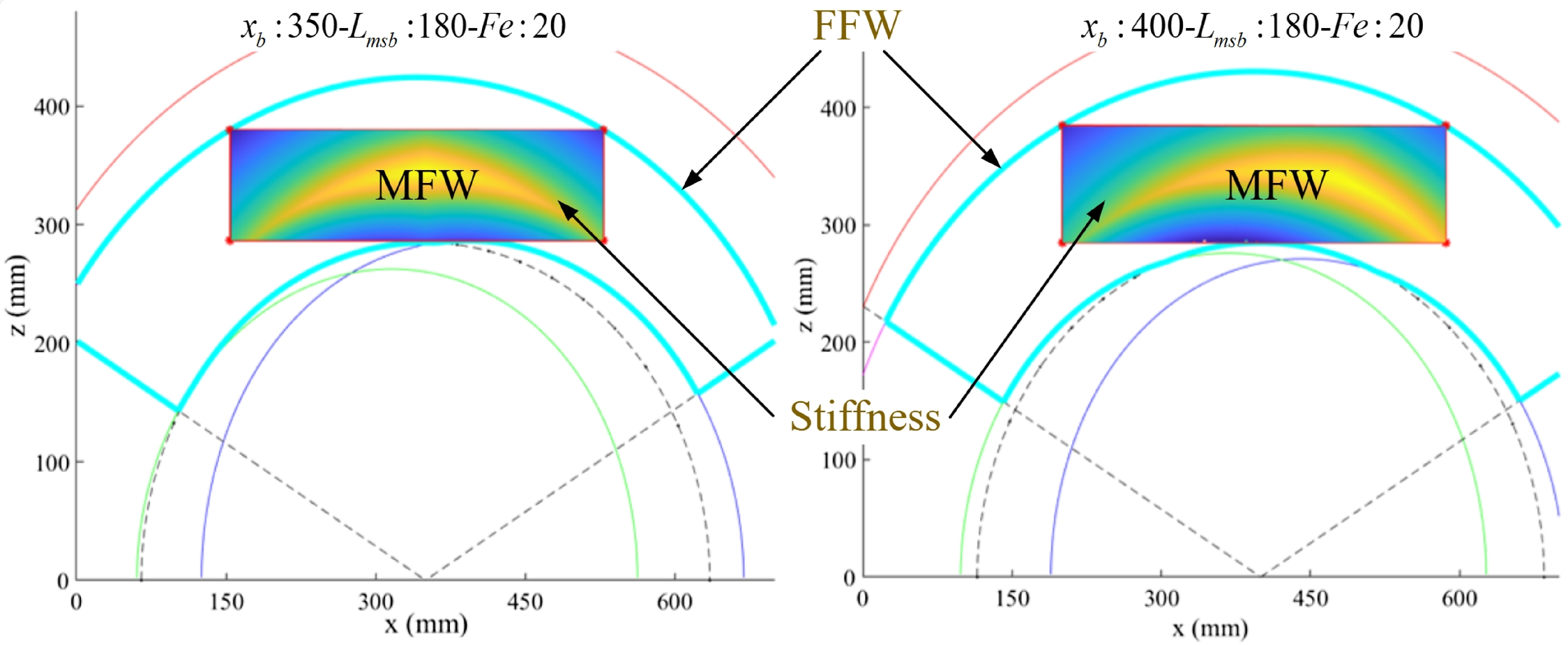
The boundary contour distribution of the designed FFW of RCDPR varies greatly under different configurations, as shown in Figure 10, which respectively show the boundary contour distribution of RCDPR under different hinge positions
 $x_{b}$
, spring positions
 $L_{msb}$
and external forces
 $F_{e}$
. The corresponding
 $S_{\Theta }$
solution process can be designed through the number of intersections of each boundary contour and its distribution, and the overall design of the boundary contour algorithm (BCA) can be completed. As the distribution of boundary contours is more diverse, but the calculation process of
 $S_{\Theta }$
is more similar, it will not be repeated in this paper.
Distribution of FFW boundary contours of RCDPR under different structures and different interferences.

3.4. FFW solution based on boundary contour algorithm
This section takes the structural parameters of RCDPR, hinge position
 $x_{b}$
, spring position L
msb
, and external force F
e
as the research objects and uses MATLAB to program the boundary contour algorithm (BCA). Then, PSA and BCA are used to solve the FFW under different
 $x_{b}$
, L
msb
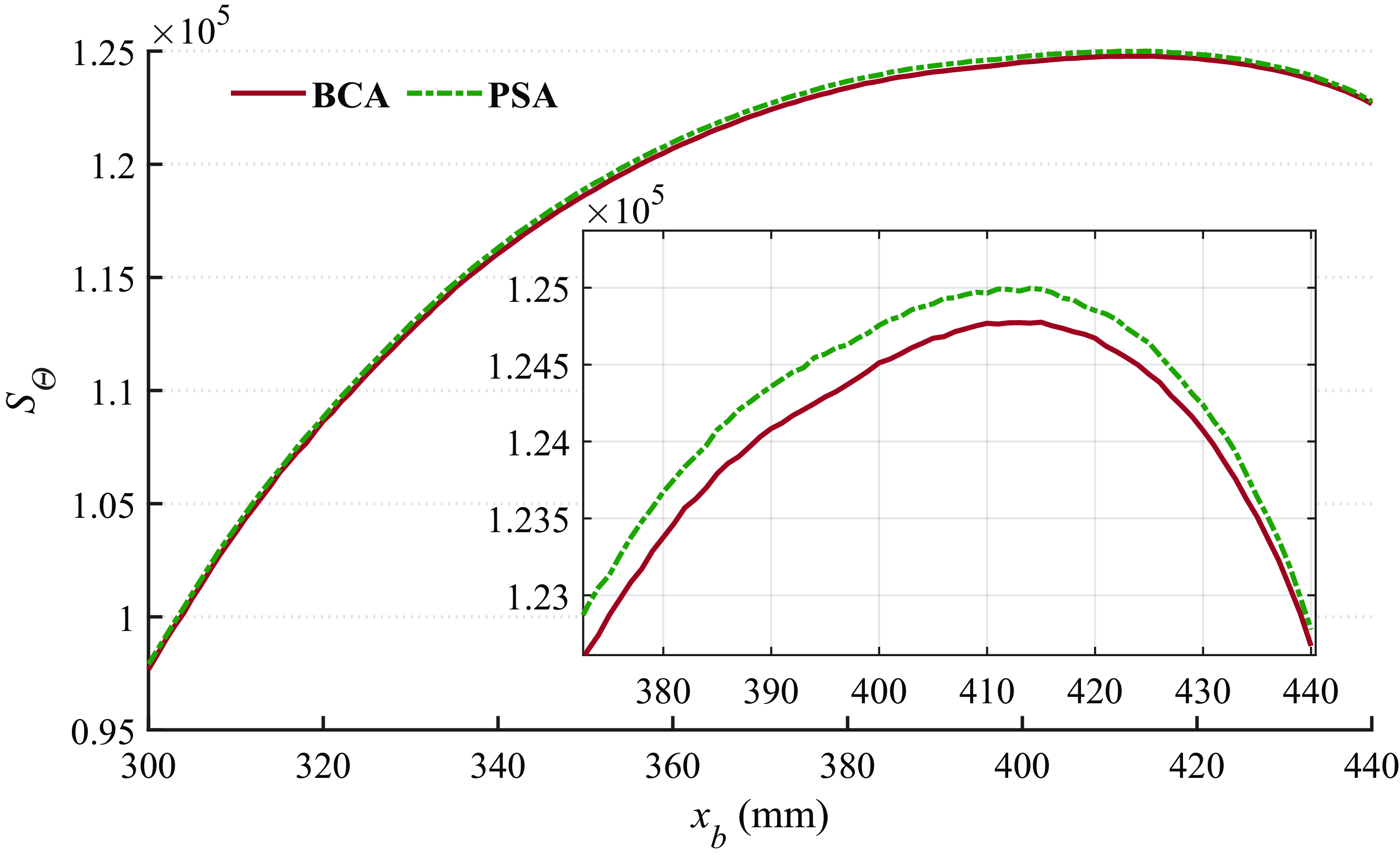
and F
e
to verify the accuracy and efficiency of BCA, as shown in Figure 11. Figure 12 shows the FFW of PSA and BCA under continuous changes in
 $x_{b}$
. The solution times of BCA, PSA, and PSA under the Monte-Carlo method are shown in Table 1. The computer configuration used for the simulation is CPU: Intel(R) I5-13400@2.5 GHz, RAM: 16 GB.
FFW based on BCA and PSA.

The area
 $S_{\Theta }$
of FFW solved by BCA and PSA.

Figures 11 and 12 indicate that the designed BCA can accurately and quickly solve the FFW of RCDPR under different configurations and external force. Compared with the PSA, the solution accuracy is higher than the grid search method, and the calculation time is shortened by about 99%. BCA greatly improves the calculation efficiency and provides theoretical support for the rapid structural optimization and dynamic reconfiguration of RCDPR.
4. Stability optimization design of RCDPR
This section will theoretically model the stiffness and CFS of RCDPR, further analyze the FFW of RCDPR and complete the design of the RCDPR stability evaluation function.
Solution time for FFW of central surface forces.

4.1. Stiffness modeling analysis of RCDPR
The stiffness of the RCDPR end effector depends on the cable, the structure of the RCDPR, springs and external forces, which significantly affect the stability of the end effector. Therefore, its structural stiffness needs to be modeled in stability design. The force stiffness k i of the cable is expressed as
 \begin{equation} k_{i}=T_{i}/\left(l_{i}-l_{i}^{o}\right) \end{equation}
Where
 $l_{i}^{o}$
is the original length of the cable.
In addition, considering the elasticity of the cable, k i can be expressed as
 \begin{equation} k_{i}= \displaystyle\frac{1}{\dfrac{1}{k_{i}^{d}}+ \displaystyle\frac{l_{i}^{o}}{E_{s}A_{s}}} \end{equation}
Where A S is the cross-sectional area of the cable, and E S is the elastic modulus of the cable. Then, the cable stiffness k k can be expressed as
 \begin{equation} k_{k}=\frac{E_{s}A_{s}}{l_{i}^{o}}=\frac{k_{f}}{l_{i}^{o}} \end{equation}
Where
 $k_{f}=E_{s}A_{s}$
. Subsequently, Eq. (39) can be rewritten as
 \begin{equation} k_{i}= \displaystyle\frac{1}{\dfrac{1}{k_{i}^{d}}+\displaystyle\frac{l_{i}^{o}}{E_{s}A_{s}}}=\displaystyle\frac{k_{i}^{d}k_{f}}{k_{f}+k_{i}^{d}l_{i}^{o}} \end{equation}
Where
 $k_{i}^{d}$
is the drive unit stiffness. In addition, k
k
can be derived as
 \begin{equation} k_{k}=\frac{k_{f}}{l_{i}}\left(1+\frac{T_{i}}{k_{f}}\right) \end{equation}
Combining Eqs. (41) and (42),
 $k_{i}$
is derived as
 \begin{equation} k_{i}=\displaystyle\frac{k_{i}^{d}k_{f}}{k_{f}+k_{i}^{d}l_{i}^{o}}=\displaystyle\frac{k_{i}^{d}\displaystyle\frac{k_{f}}{l_{i}^{o}}}{\displaystyle\frac{k_{f}}{l_{i}^{o}}+k_{i}^{d}}=\displaystyle\frac{k_{i}^{d}k_{k}}{k_{k}+k_{i}^{d}}=\displaystyle\frac{k_{i}^{d}\left(\displaystyle\frac{k_{f}}{l_{i}}\left(1+\displaystyle\frac{T_{i}}{k_{f}}\right)\right)}{\displaystyle\frac{k_{f}}{l_{i}}\left(1+\displaystyle\frac{T_{i}}{k_{f}}\right)+k_{i}^{d}}=\displaystyle\frac{k_{i}^{d}k_{f}l_{i}^{-1}\left(1+T_{i}{k_{f}}^{-1}\right)}{k_{f}l_{i}^{-1}\left(1+T_{i}{k_{f}}^{-1}\right)+k_{i}^{d}} \end{equation}
Due to cable force
 $k_{i}^{d}\gt \gt k_{k} , k_{i}$
is derived as
 \begin{equation} k_{i}=\frac{k_{i}^{d}k_{f}l_{i}^{-1}\left(1+T_{i}{k_{f}}^{-1}\right)}{k_{f}l_{i}^{-1}\left(1+T_{i}{k_{f}}^{-1}\right)+k_{i}^{d}}\approx k_{f}l_{i}^{-1}\left(1+T_{i}{k_{f}}^{-1}\right) \end{equation}
Based on Eq. (44), since
 $T_{i}\leq k_{f}$
, the active stiffness adjusted by the cable force will be neglected.
 \begin{equation} \mathbf{K}_{i}=k_{f}{\rm diag}\left(\frac{1}{l_{1}},\frac{1}{l_{2}},\frac{1}{l_{3}}\ldots ,\frac{k_{s}}{k_{f}}\right) \end{equation}
Then, the structural stiffness K c of RCDPR can be expressed as
 \begin{equation} \mathbf{K}_{c}=k_{f}\mathbf{J}{\rm diag}\left(\frac{1}{l_{1}},\frac{1}{l_{2}},\frac{1}{l_{3}}\ldots ,\frac{k_{s}}{k_{f}}\right)\mathbf{J}^{T}=E_{s}A_{s}\mathbf{J}{\rm diag}\left(\frac{1}{l_{1}},\frac{1}{l_{2}},\frac{1}{l_{3}}\ldots ,\frac{k_{s}}{E_{s}A_{s}}\right)\mathbf{J}^{T} \end{equation}
Then calculate the stiffness value of the end effector at the position (350, 350, 300), as
 \begin{equation} \mathbf{K}_{c}\left(\begin{array}{lll} 350 & 350 & 300 \end{array}\right)=\left[\begin{array}{lll} 1.4056 & & \\ & 1.5936 & \\ & & 1.3744 \end{array}\right]\times 10^{6}\,\mathrm{N}/\mathrm{m} \end{equation}
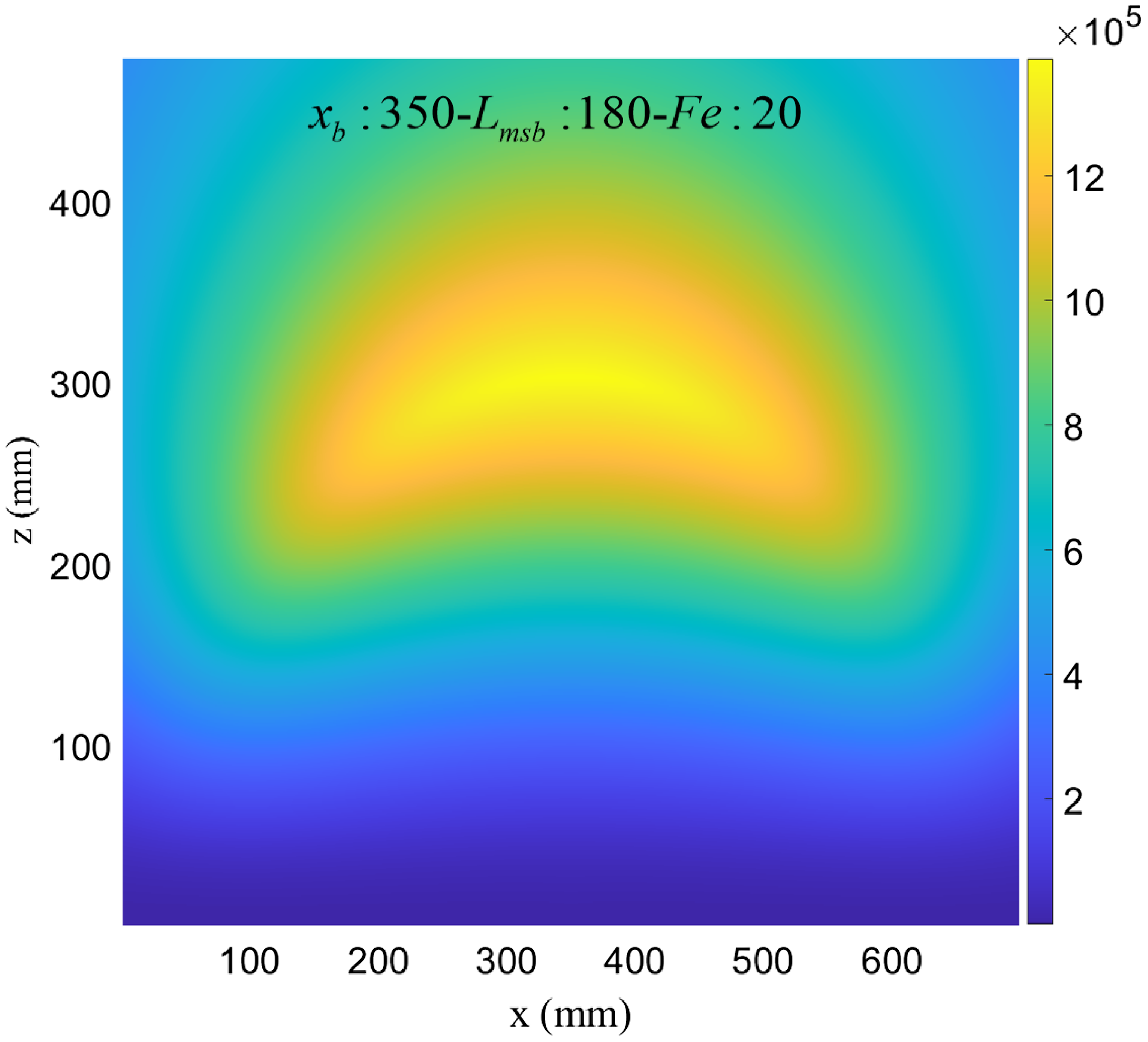
Figure 13 shows the stiffness distribution of the central plane in a certain configuration of RCDPR. In the simulation model, The elastic modulus of the cable selected E
S
= 70.5 Gpa, the cross-sectional area A
S
= 0.7854, and the spring stiffness is
 $k_{s}$
=1000 N/m. Combined with the numerical calculation results, the stiffness model of RCDPR is larger, with an order of magnitude of 106. The cable force is generally less than 100 N and has little impact on the total stiffness, so it is ignored in the subsequent stability optimization design.
Stiffness distribution of the central plane.

4.2. Cables driving force space of RCDPR
In the stiffness analysis, the influence of the cable forces is ignored due to the minor active stiffness. However, instability, driving performance evaluation or actual operation, the cable forces of the cable have a more significant impact on the robot’s performance. The forces determine the anti-interference ability and driving performance of the end effector. Therefore, it is still necessary to design the CFS into the stability evaluation function.
Given any position of the RCDPR, it is possible to determine the force set that the cables can apply to the end effector, and it can be determined that the end effector can apply all force sets to the surrounding environment. CFS is the feasible force set that the end effector can apply to its surrounding environment. Combining Eq. (21), the mathematical expression of the feasible force set
 $F^{\Omega }$
is derived as
 \begin{equation} F^{\Omega }=\left\{\left.\Omega \in \mathbf{R}^{n}\right| \colon \Omega =\sum _{i=1}^{m}T_{i}\mathbf{J}_{i},T_{\min }\leq T_{i}\leq T_{\max }\right\} \end{equation}
where Ω the set of end effector output forces. Subsequently, Eq. (48) can be rewritten as
 \begin{equation} F^{\Omega }=\left\{\left.\Omega \in \mathbf{R}^{n}\right| \colon \Omega =\sum _{i=1}^{m}\left(\varphi _{i}\mathbf{J}_{i}+T_{\min }\mathbf{J}_{i}\right),0\leq \varphi _{i}\leq \left(T_{\max }-T_{\min }\right)\right\} \end{equation}
where
 \begin{equation} \varphi _{i}=T_{i}-T_{\min } \end{equation}
Furthermore, Eq. (49) can be transformed into
 \begin{equation} F^{\Omega }=\left\{\left.\Omega \in \mathbf{R}^{n}\right| \colon \Omega =\sum _{i=1}^{m}\beta _{i}\overline{T}\mathbf{J}_{i}+\Omega _{\min },0\leq \beta _{i}\leq 1\right\} \end{equation}
In which
 \begin{equation} \overline{T}=T_{\max }-T_{\min },\,\,\,\Omega _{\min }=\sum _{i=1}^{m}T_{\min }\mathbf{J}_{i} \end{equation}
 \begin{equation} \beta _{i}=\frac{\varphi _{i}}{\overline{T}}=\frac{T_{i}-T_{\min }}{T_{\max }-T_{\min }} \end{equation}
Therefore,
 $F^{\Omega }$
can be regarded as the vector sum of a finite number of closed line segments in Euclidean space. Zonotope refers to the Minkowski Sum of some limited closed line segments in Euclidean space [Reference Rasheed, Long and Marquez-Gamez18]. Minkowski Sum can be applied between polyhedrons, and the Minkowski Sum of two convex polyhedrons is still a convex polyhedron. The feasible force set of RCDPR at the end effector can be regarded as the sum of vector line segments (Minkowski Sum) of the cables under a specific force range, and the zonotope can be formed by Minkowski Sum.
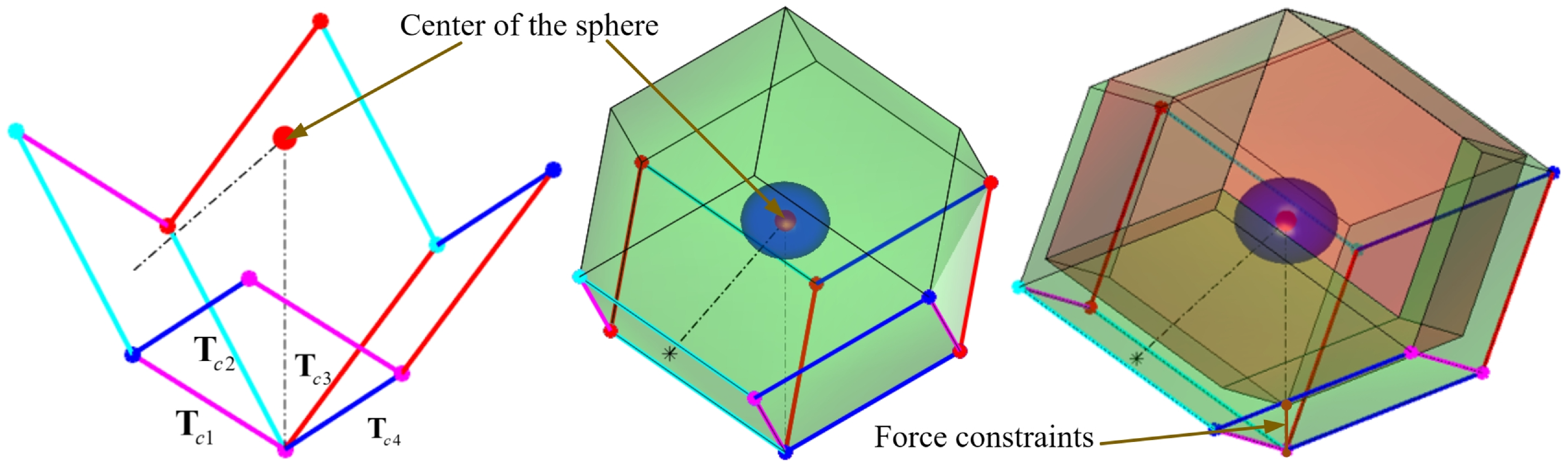
The designed RCDPR structure comprises four parallel cables in tension with a compression spring. The force constraints of the four parallel cables translate the Zonotope’s hyperplane, as shown in Figure 14. This paper defines the minimum value of the maximum external force in all directions that the RCDPR’s current posture can withstand as CFS. Its geometric form is expressed as an inscribed sphere of a zonotope composed of four parallel cables, and the position of the center of the sphere can be determined by the spring compression force vector. For the designed CFS of the Zonotope of RCDPR, according to the tangent point of the inscribed sphere located on the plane formed by adjacent cables or opposite cables, this paper designed a CFS solution algorithm based on vector operations.
Zonotope model of RCDPR.

When the tangent point is on the adjacent sides, the value
 $F_{\min }^{s}$
of CFS can be expressed as
 \begin{equation} F_{\min }^{s}=\min \left\{\begin{array}{ll} \left(\left| \mathbf{F}_{B1}\bullet \mathbf{F}_{s}\right| -\left| \mathbf{F}_{B1}\bullet \mathbf{F}_{c4}\right| \right) & \left(T_{\max }\left| \mathbf{F}_{B1}\bullet \mathbf{F}_{c}\right| -\left| \mathbf{F}_{B1}\bullet \mathbf{F}_{s}\right| \right) \end{array}\right\} \end{equation}
In which
 \begin{equation} \mathbf{F}_{B1}=\frac{\mathbf{T}_{c1}\bullet \mathrm{T }_{c4}}{\left| \mathbf{T}_{c1}\bullet \mathrm{T }_{c4}\right| } \end{equation}
 \begin{equation} \mathbf{F}_{c}=\mathbf{T}_{c2}+\mathbf{T}_{c3},\,\,\,\,\,\mathbf{F}_{c4}=T_{\min }\mathbf{F}_{\min } \end{equation}
where
 $\mathbf{F}_{s}$
is the spring force vector of the end effector at the current position.
 $\mathbf{F}_{\min }$
is the lower boundary constraint vector of the cables force,
 $\mathbf{F}_{\min }=\Omega _{\min }$
.
 $\mathbf{T}_{c1}$
,
 $\mathbf{T}_{c2}$
,
 $\mathbf{T}_{c3}$
,
 $\mathbf{T}_{c4}$
are the force vectors of the four cables, and
 $\bullet$
is vector cross product.
When the tangent point is on the opposite sides,
 $F_{\min }^{s}$
can be expressed as
 \begin{equation} F_{\min }^{s}=\min \left\{\begin{array}{ll} \left(T_{\max }\left| \mathbf{F}_{B2}\cdot \mathbf{T}_{c4}\right| -\left| \mathbf{F}_{B2}\cdot \mathbf{F}_{s}\right| +\left| \mathbf{F}_{B2}\cdot \mathbf{F}_{c2}\right| \right) & \left(T_{\max }\left| \mathbf{F}_{B2}\cdot \mathbf{T}_{c2}\right| -\left| \mathbf{F}_{B2}\cdot \mathbf{F}_{s}\right| +\left| \mathbf{F}_{B2}\cdot \mathbf{F}_{c1}\right| \right) \end{array}\right\} \end{equation}
In which
 \begin{equation} \mathbf{F}_{B2}=\frac{\mathbf{T}_{c1}\cdot \mathbf{T}_{c3}}{\left| \mathbf{T}_{c1}\cdot \mathbf{T}_{c3}\right| } \end{equation}
 \begin{equation} \mathbf{F}_{c1}=T_{\min }\left(\mathbf{T}_{c3}+\mathbf{T}_{c4}\right)\mathbf{F}_{c2}=T_{\min }\left(\mathbf{T}_{c2}+\mathbf{T}_{c3}\right) \end{equation}
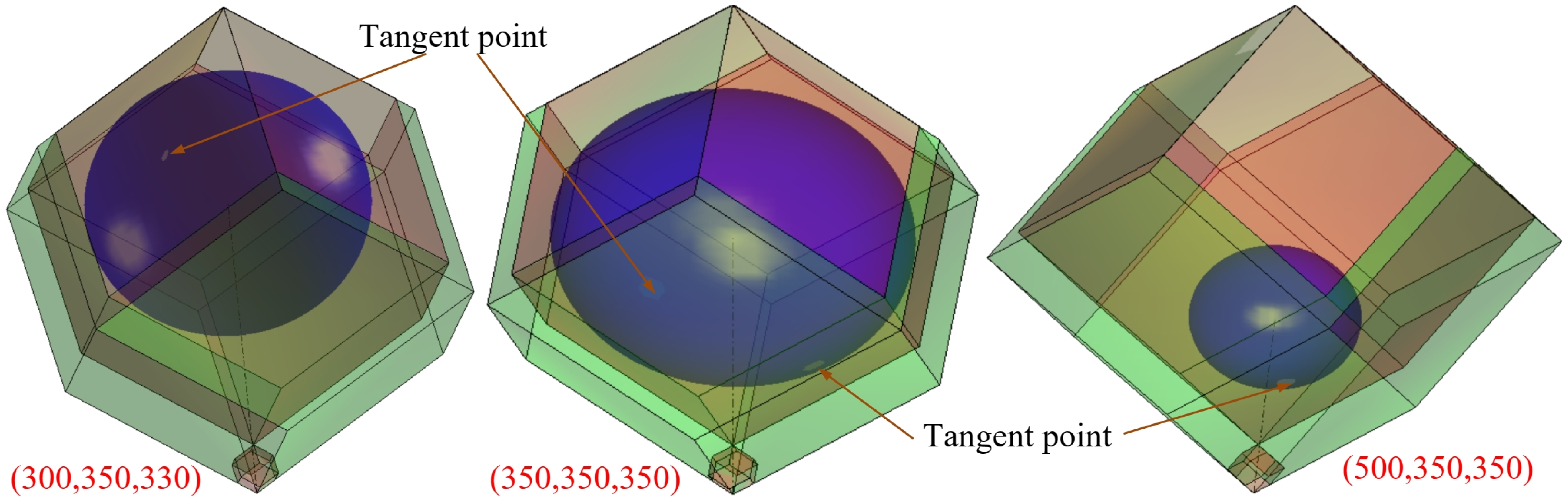
Then, the inscribed sphere of the RCDPR with the end effector at different positions is solved, and the drawing results are shown in Figure 15. Numerical simulation results verify the accuracy of this algorithm in solving CFS. Only vector operations are used for calculation, which avoids solving equations and iterative processes and has the advantages of simple calculation and high efficiency.
Inscribed sphere of the RCDPR with the end effector at different positions.

4.3. Design and solution of main task feasible workspace of RCDPR
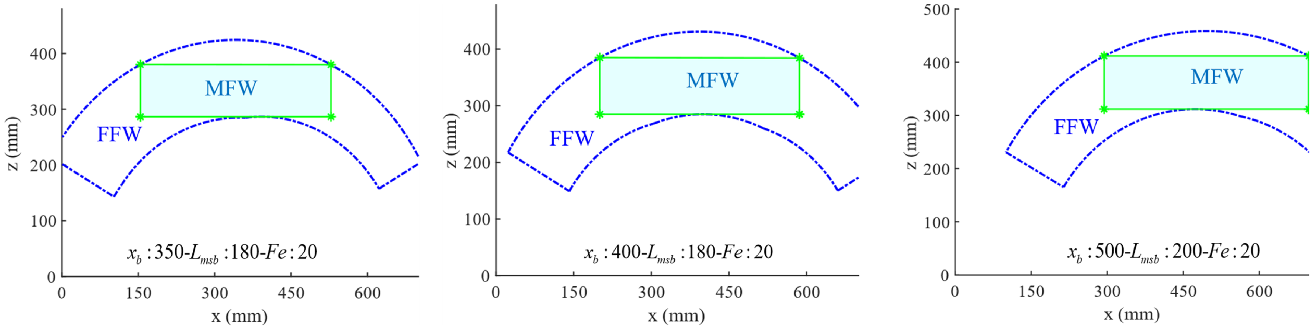
The BCA is used in this paper to solve the FFW of RCDPR. The FFW of the RCDPR space is approximately the FFW at the central plane rotated around the x-axis. FFW is shown in the area surrounded by the blue dotted line in Figure 16. Most areas have poor application performance, and the CFS in the edge area of FFW is low. Combined with the stiffness simulation results of RCDPR, the central area has relatively good stiffness. Therefore, this paper further establishes the MFW, a commonly used area within FFW with better motion performance. According to the needs of actual operations or other working conditions, MFW is defined as the cylindrical area facing vertically toward the workpiece, that is, the largest inscribed rectangle within the FFW. The solution method is to combine the established FFW boundary equation and establish the FFW inscribed rectangle equation through the gradient descent method. The MFW is shown in the cyan area in Figure 16. The stiffness performance within the MFW is shown in Figure 17.
Distribution of MFW and FFW.

Stiffness distribution within the MFW.

4.4. Design of stability evaluation function
According to the FFW, MFW, CFS, and stiffness models established above, the stability evaluation function based on force-position workspace is further established. The positional stability of the RCDPR’s end effector is represented by stiffness, CFS is used to evaluate the mechanical properties of the RCDPR, and the stability function of the RCDPR is designed using FFW and MFW as carriers. The objective parameters include stiffness, FFW, MFW, and CFS. The order of magnitude of each objective parameter is shown in Table 2.
As presented in Table 2, there are significant differences in the order of magnitude of each objective parameter. Therefore, it is necessary to unify the dimensions of each parameter and perform nonlinear weighting according to the impact of different objectives. The process is as follows:
First, the FFW and MFW will be weighted and unified.
 $S_{M}$
is the area of MFW. As shown in Table 2, the order of magnitude of MFW is usually lower than that of FFW. However, in actual operations, the MFW is used more frequently, so it is necessary to perform a weighted design on FFW and MFW. The specific method is to calculate the average area of FFW and MFW under different configurations. Then construct the weight coefficient
 $\vartheta _{S}$
based on their ratio. The mathematical expression is
 \begin{equation} \vartheta _{S}=\displaystyle\frac{\displaystyle\frac{1}{100}\sum _{i=1}^{100}S_{M}^{i}}{\displaystyle\frac{1}{100}\sum _{i=1}^{100}S_{\Theta }^{i}} \end{equation}
where i is 100 sets of variable combinations randomly selected in the optimization interval
 $x_{b}\in (\begin{array}{ll} 250 & 450 \end{array})$
and
 $L_{msb}\in (\begin{array}{ll} 180 & 300 \end{array})$
.
 $S_{\Theta }^{i}$
and
 $S_{M}^{i}$
are the areas of FFW and MFW under the current configuration, respectively.
The order of magnitude of the objective parameters.

The weighted area
 $S_{F}^{M}$
of FFW and MFW is expressed as
 \begin{equation} S_{F}^{M}=\vartheta _{S}S_{\Theta }+\left(1-\vartheta _{S}\right)S_{M} \end{equation}
Then,
 $S_{F}^{M}$
is weighted by stiffness and CFS, respectively, to construct the objective function F
g
. First, solve the average stiffness
 $K_{n}^{c}$
under the current configuration, and its mathematical expression is
 \begin{equation} K_{n}^{c}=\frac{1}{n_{x}n_{z}}\sum _{n_{z}}\sum _{n_{z}}K_{nx,nz}^{c} \end{equation}
The average CFS
 $F_{n}^{c}$
under the current configuration is expressed as
 \begin{equation} F_{n}^{c}=\frac{1}{n_{x}n_{z}}\sum _{n_{z}}\sum _{n_{z}}F_{nx,nz}^{s,\min } \end{equation}
where
 $n_{x}$
and
 $n_{z}$
are the number of uniform sampling points in the interval of the length and width of MFW, respectively.
 $K_{nx,nz}^{c}$
and
 $F_{nx,nz}^{s,\min }$
are the stiffness (K
c) and CFS (
 $F_{\min }^{s}$
) at the current sampling position, respectively.
The stability evaluation function F g is expressed as
 \begin{equation} F_{g}={\unicode[Arial]{x03A8}} \left(\frac{K_{n}^{c}}{K_{\max }}\right)S_{F}^{M}+{\unicode[Arial]{x03A8}} \left(\frac{F_{n}^{c}}{F_{\max }}\right)S_{F}^{M} \end{equation}
where
 ${\unicode[Arial]{x03A8}}$
is the weighting function. K
max is the global maximum stiffness of the central plane, and F
max is the theoretical maximum CFS.
Since the stiffness in some configurations is large and sensitive to position changes, the maximum CFS changes little. The stiffness and CFS are nonlinearly weighted through a Gaussian function to remove extreme positions and further increase the weight of the CFS. Set δ
1 = 1.5, δ
2 = 0.5. In summary, the stability evaluation function
 $F_{g}$
is expressed as
 \begin{equation} F_{g}=\left(\exp \left(-\displaystyle\frac{^{{\left(\displaystyle\frac{k_{n}^{c}}{k_{\max }}-1\right)^{2}}}}{2{\delta _{1}}^{2}}\right)+\exp \left(-\displaystyle\frac{^{{\left(\displaystyle\frac{F_{n}^{c}}{F_{\max }}-1\right)^{2}}}}{2{\delta _{2}}^{2}}\right)\right)S_{F}^{M} \end{equation}
Based on the stability evaluation function
 $F_{g}$
designed above, this paper uses the grid search method to optimize the parameters of variables
 $x_{b}$
and L
msb
of RCDPR. The size and model of some components of RCDPR need to consider the actual operation requirements. In this study, considering the availability of these components, the size of the RCDPR frame is set to 700 mm, and the mounting plate of the end effector is approximately a regular hexagon with a side length of 60 mm. The initial length of the spring is 300 mm and the stiffness is 1 N/mm. The grid search method can accurately calculate the optimal parameters of variables
 $x_{b}$
and L
msb
, where the interference external force F
e
is set in the simulation model to closely simulate the actual operating environment. This study carried out optimization simulations under two different interferences. When F
e
=[−20 0 0] N, the optimization results are hinge position
 $x_{b}$
=372 mm, and spring position L
msb
= 236 mm. When F
e
= [0 0 20] N, the optimization results are hinge position
 $x_{b}$
= 350 mm, spring position L
msb
= 251 mm.
5. Experiments
5.1. Prototype of RCDPR
Based on the optimization results, we can manually adjust the limit device to set the spring position. The hinge position can be optimized based on the actual operating environment, such as workspace distribution, stiffness, or driving force requirements, using the stability evaluation function to optimize the parameter
 $x_{b}$
. Then, the RCDPR can be reconfigured accurately and quickly through the ball screw. This paper takes the optimal configuration under the external force F
e
= [0 0 20] N as an example to carry out relevant experiments, where hinge position
 $x_{b}$
= 350 mm, spring position L
msb
= 251 mm. In this configuration, the external force F
e
can be applied stably, and the movements of the cables have a certain symmetry. This makes it easier to analyze the motion performance of the RCDPR. In addition, the RCDPR can be reconfigured by adjusting the hinge position through the ball screw and modifying the kinematic parameters. Since the experimental schemes are similar, this paper will not repeat the motion experiments under other configurations.
To validate the feasibility of the designed BCA and stability evaluation function, an experimentally scaled prototype was constructed. The stability evaluation function includes three objectives: FFW, stiffness, and CFS, but none of them can be accurately measured by sensors. This study will carry out the motion performance experiments of RCDPR and verify the feasibility of RCDPR through the motion accuracy of the end effector, the error of the cable lengths, and the fluctuation of the spring force. These data are easier to obtain and more accurate. In addition, two comparative experiments of trajectories located inside and outside the FFW will be carried out to verify the feasibility of the FFW and the practicality of the BCA.
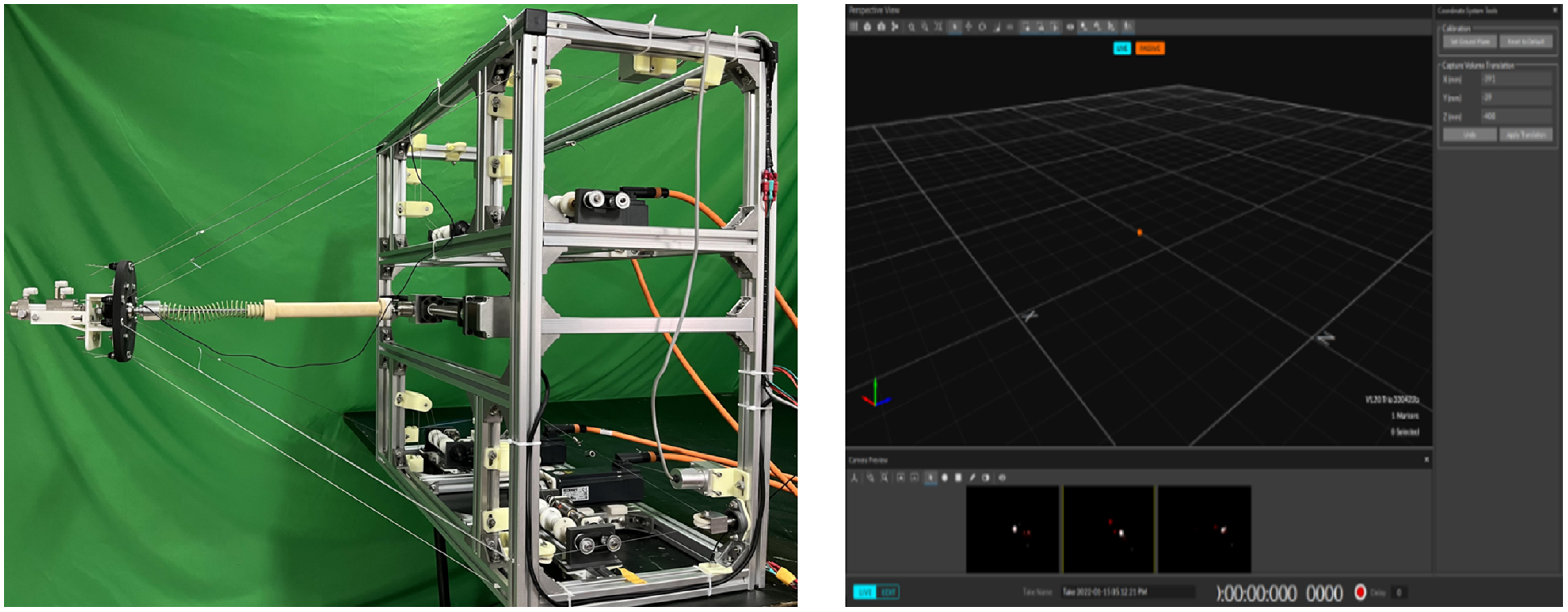
In order to obtain the actual motion trajectory of the developed RCDPR end effector, this paper uses the OptiTrack motion capture system (OptiTrack V120-Trio) with an accuracy of ±0.5 mm, which can meet the experimental requirements, as shown in Figure 18. By setting the three points of the L-shaped calibration rod as the ground coordinate system in the motive operating software, the real-time position of the robot end effector Marker point relative to the calibrated ground coordinate system can be obtained. Before conducting the kinematic control experiment, first, according to the inverse kinematics model, the relationship between the coordinate point of the robot end effector and the lengths of the cable can be obtained. Then, the RCDPR is moved to the corresponding position point, and the actual lengths of the cable are obtained through the cable displacement sensor.
Prototype of the RCDPR.

5.2. Motion performance experiment of RCDPR
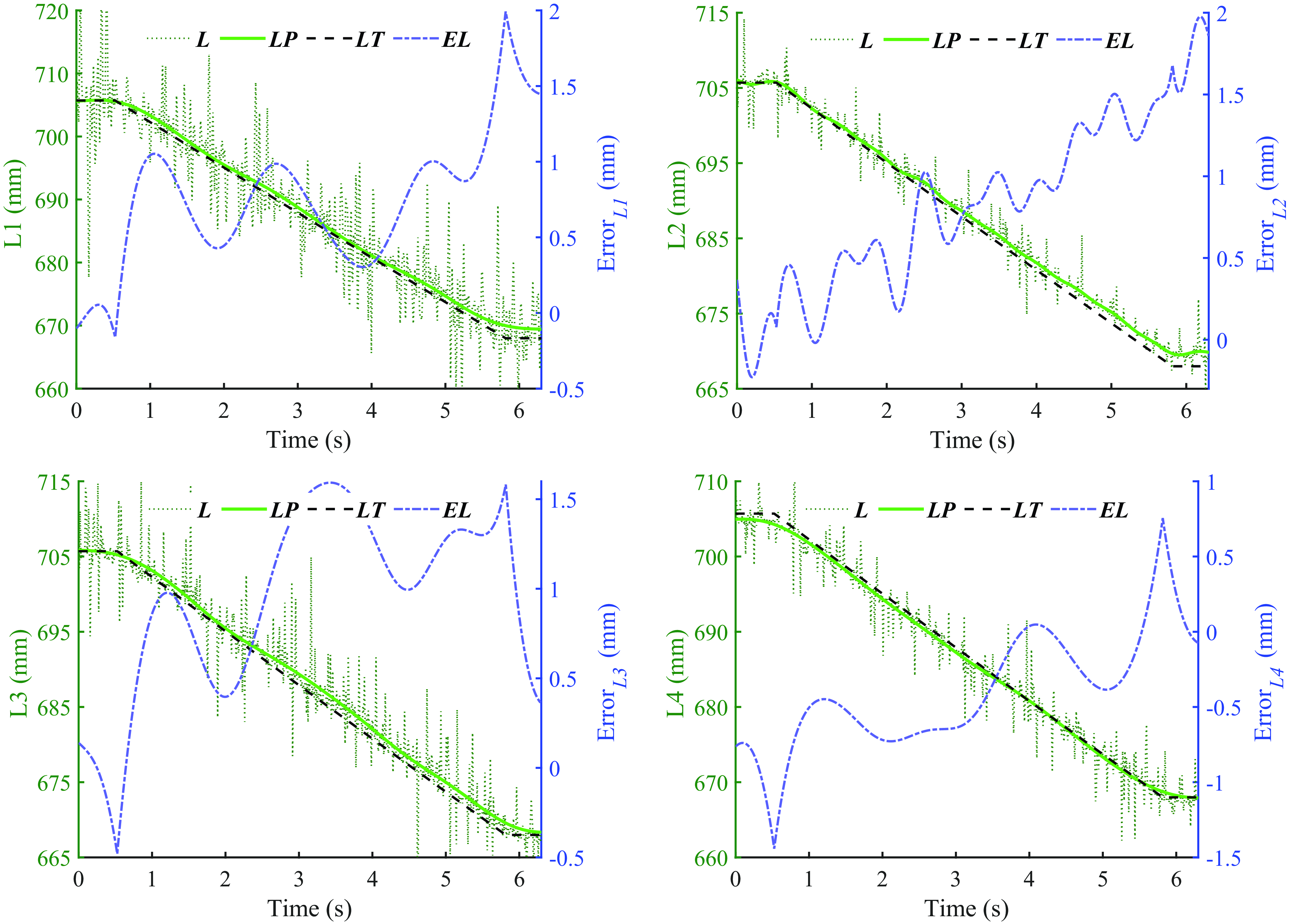
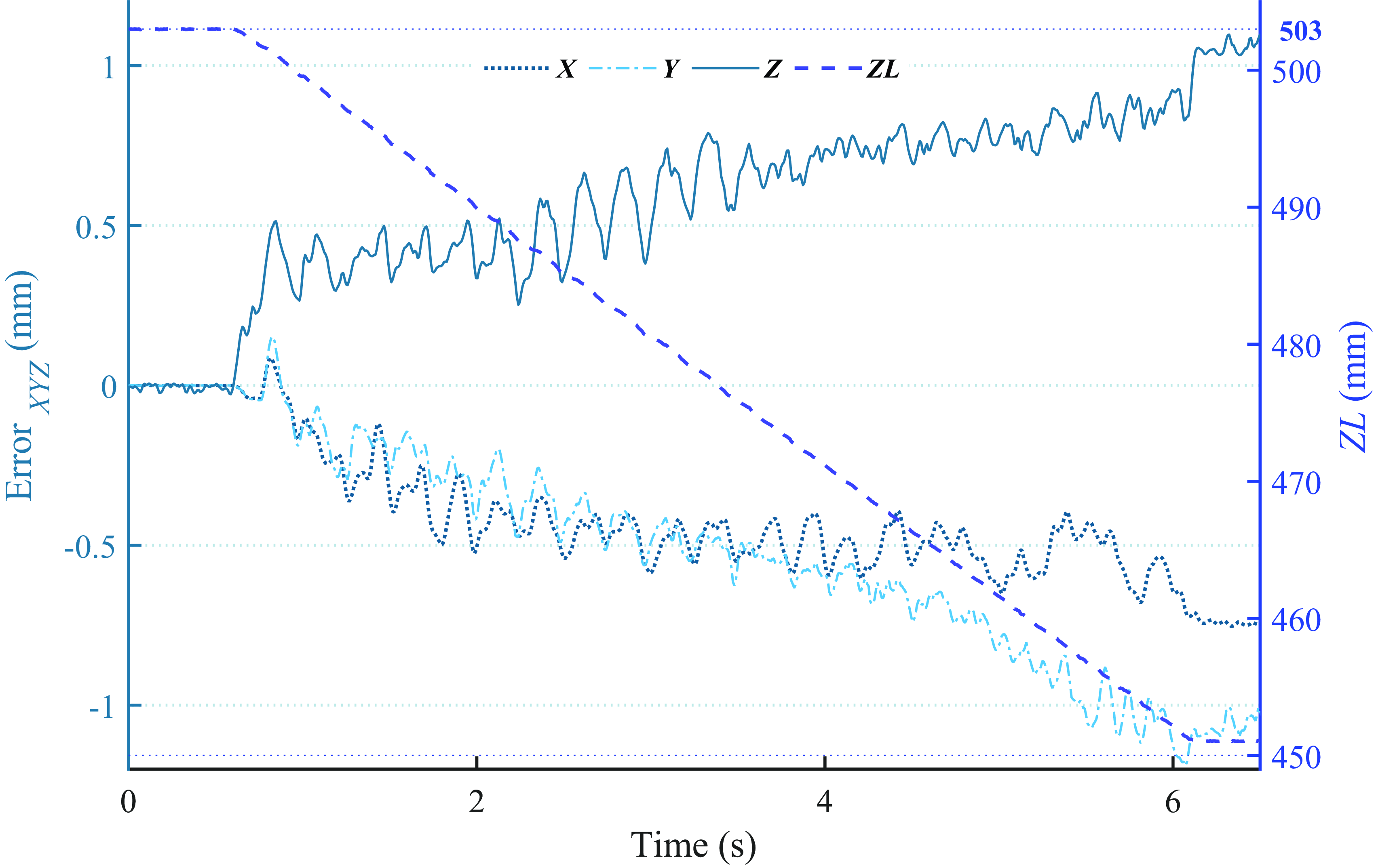
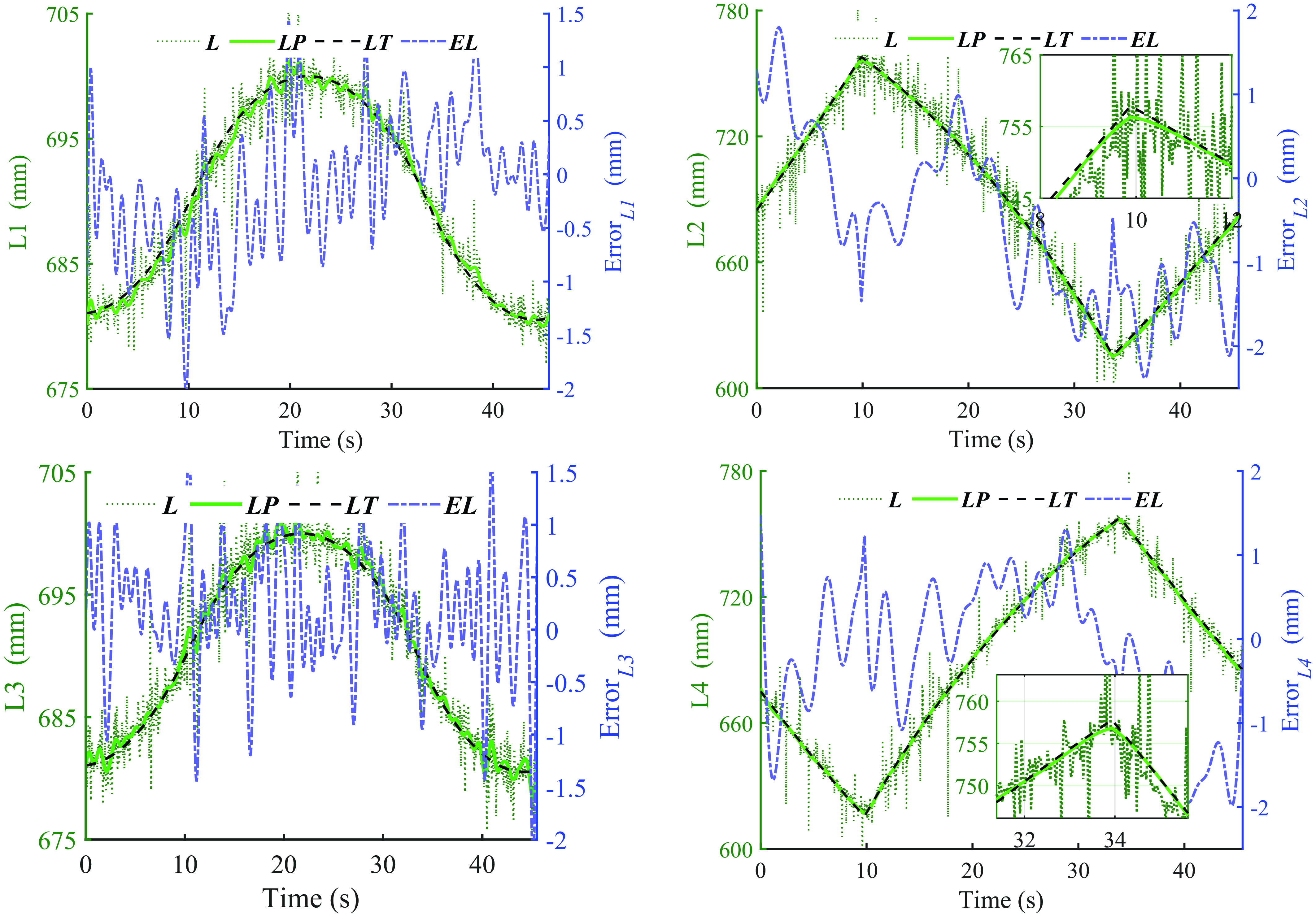
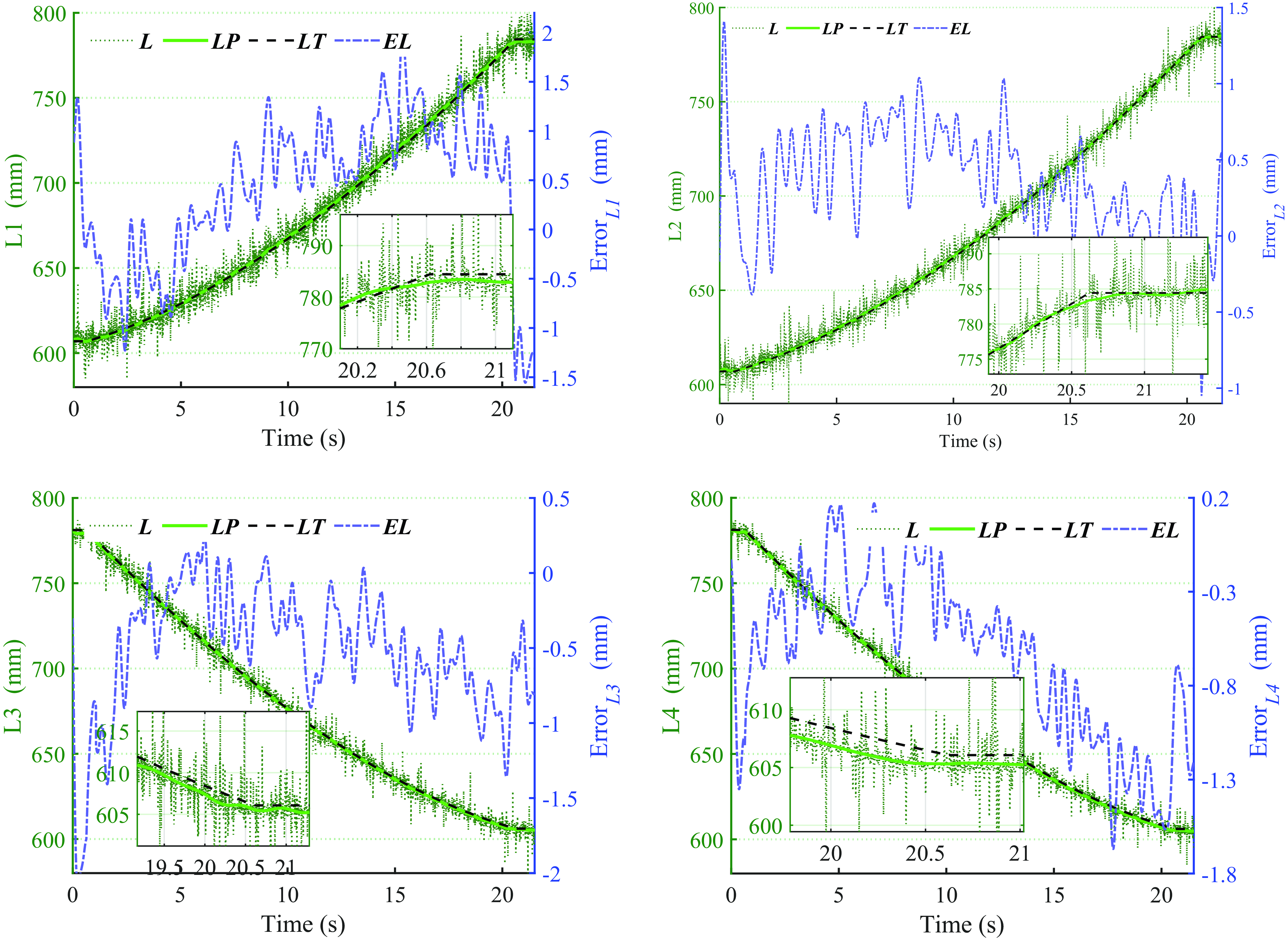
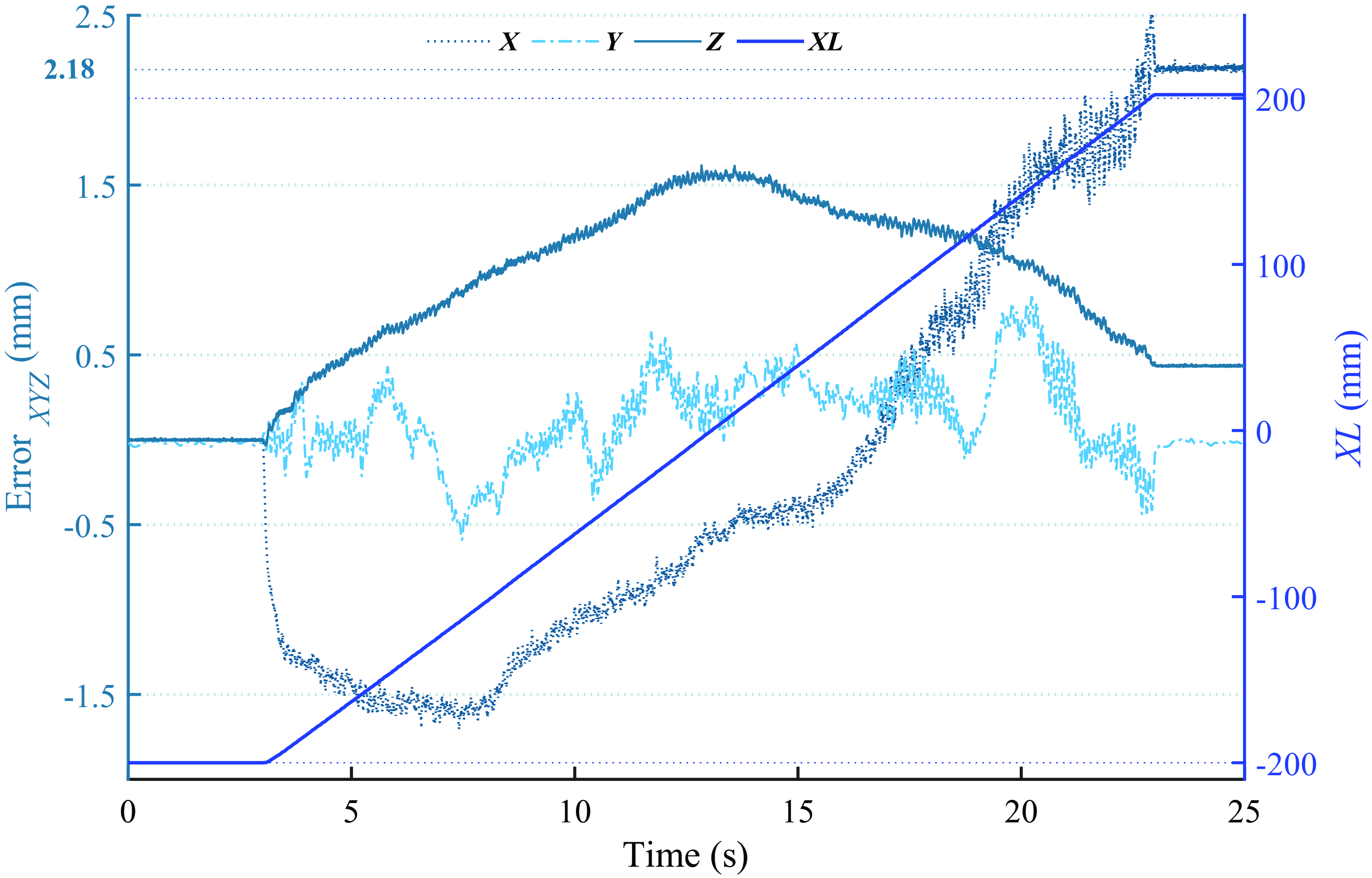
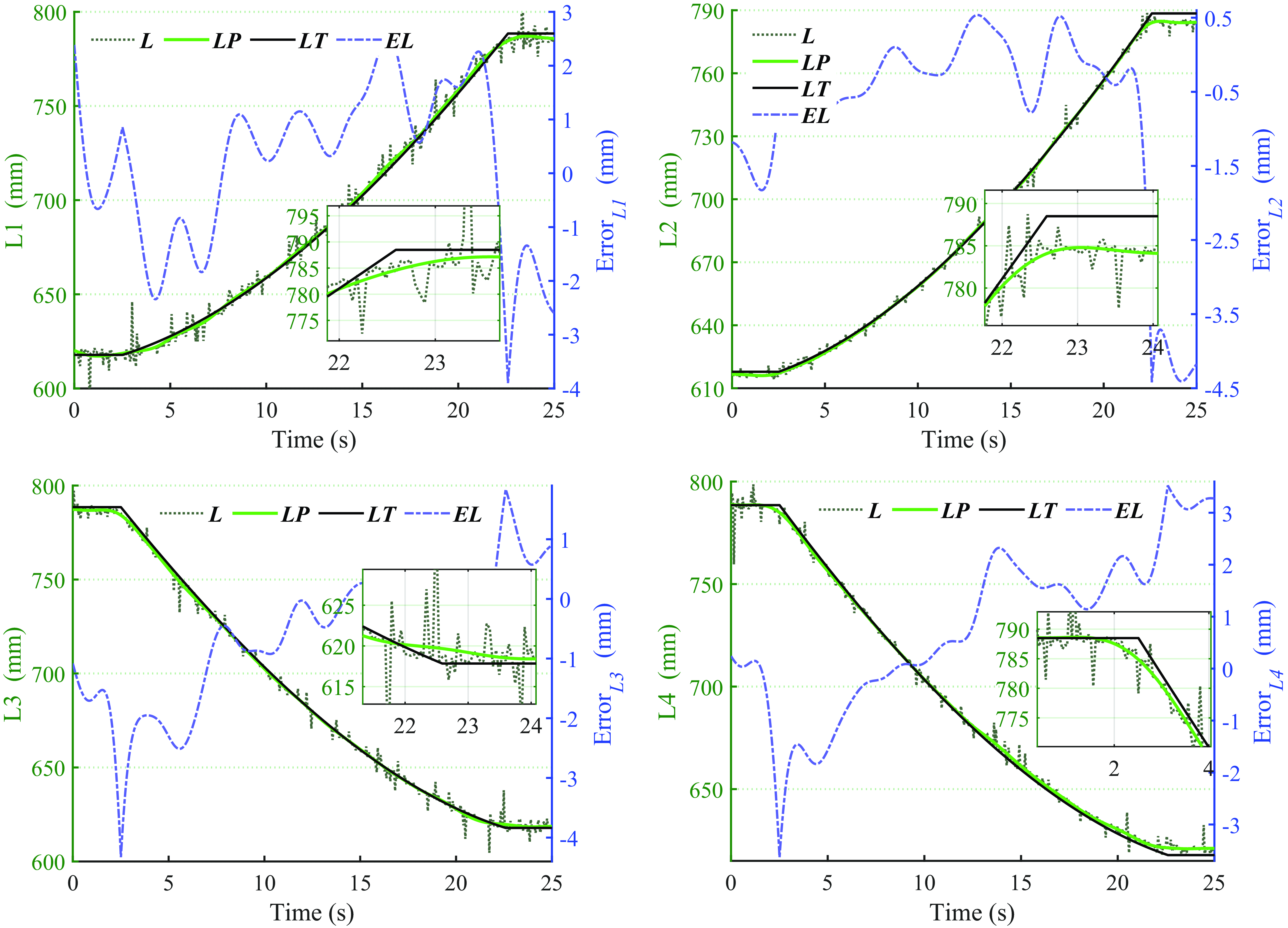
This section conducts Z-axis and spatial arc trajectory motion experiments to verify the motion performance of the designed RCDPR, and the RCDPR is placed forward to ignore external forces. The robot end effector is planned to move linearly along the Z-axis. The robot’s starting position is (345, 345, 503), which compresses the 53 mm movement along the Z-axis from the starting position to Z = 450 mm, and the moving speed is 10 mm/s. Figure 19 shows the change curve of the length of four cables when they move along the Z-axis. The spatial position change curve of the end effector center mark point measured by the trinocular vision sensor when moving along the Z axis is illustrated in Figure 20. Since the cable displacement sensors receive electromagnetic interference from motors, sensors, and other electrical equipment during operation, as well as friction and vibration between the cables and the pulleys, the collected cable length L will produce a certain amount of noise. LP is the cable lengths after filter preprocessing. The cable displacement sensor in this study all use the same filtering algorithm and related parameters.
The lengths and errors of the cables of Z-axis (L is the cable length of the sensors, LP is the filtered length, LT is theoretical length, and EL is therror of length).

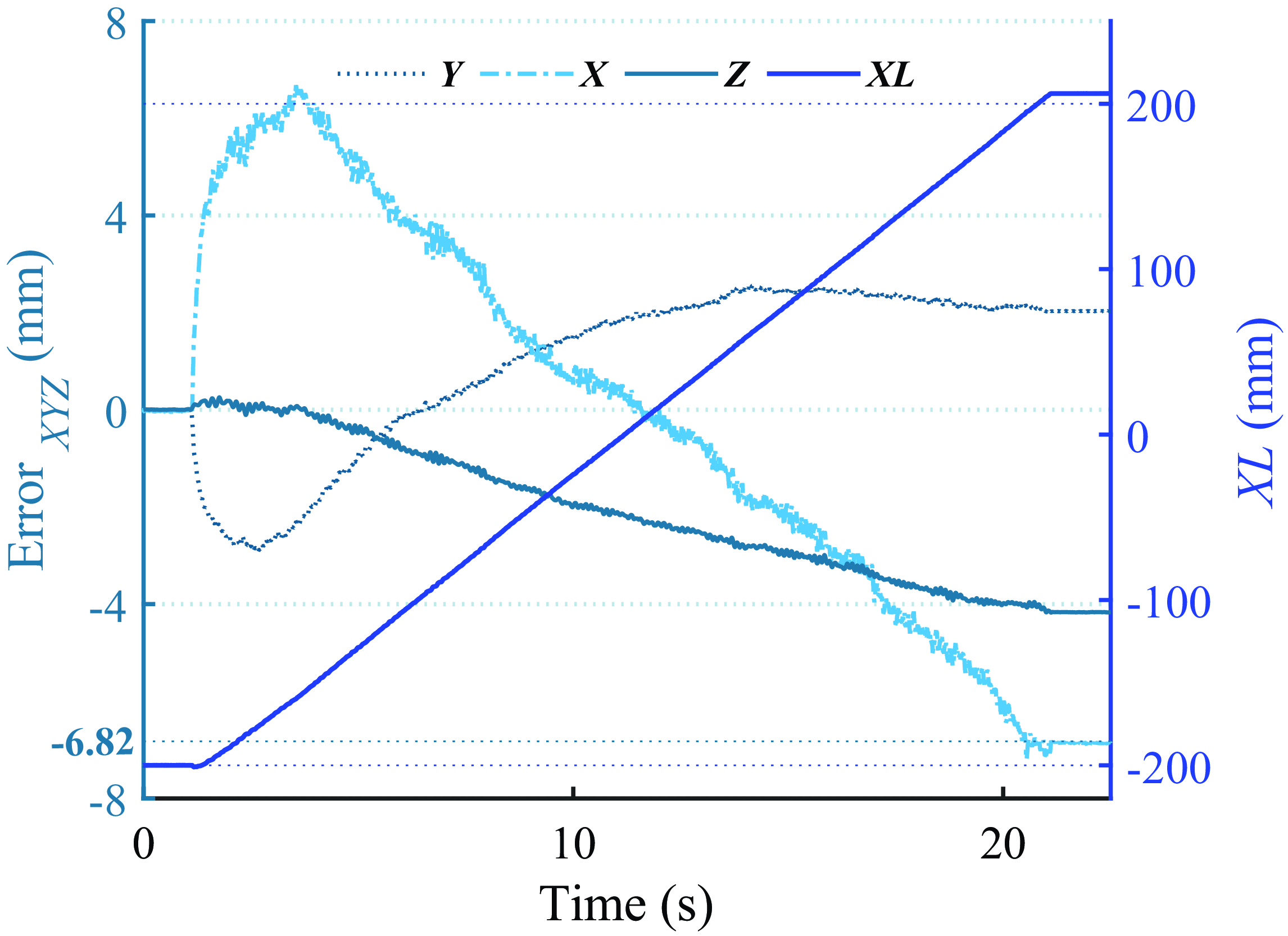
The spatial 3-DOF positions and errors of Z-axis (ZL is the position of the sensor).

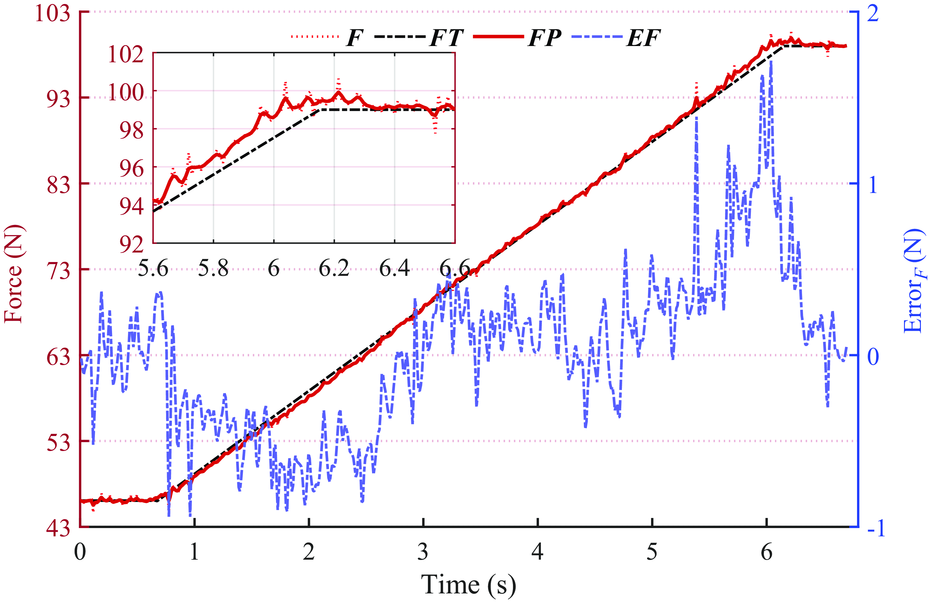
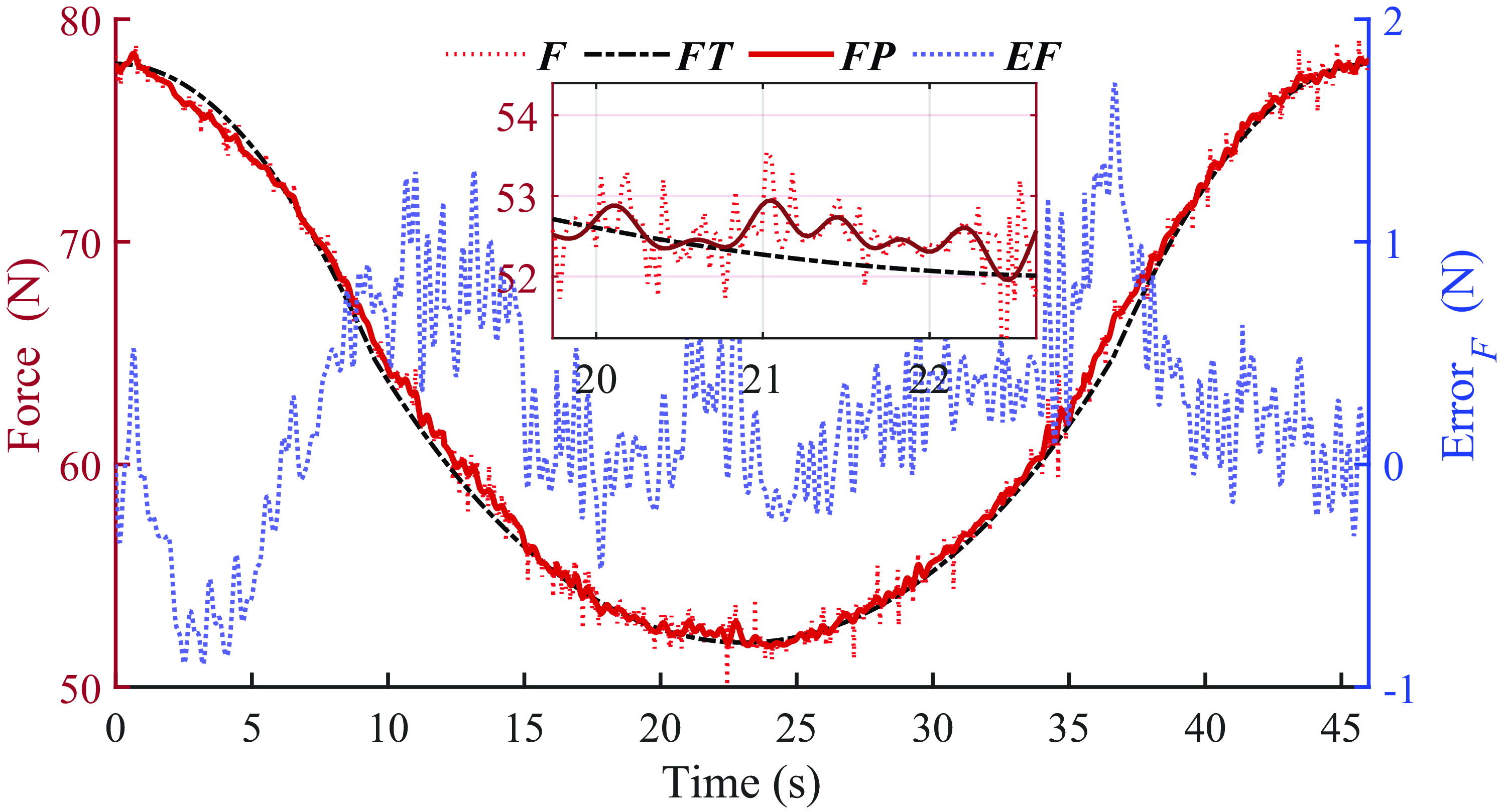
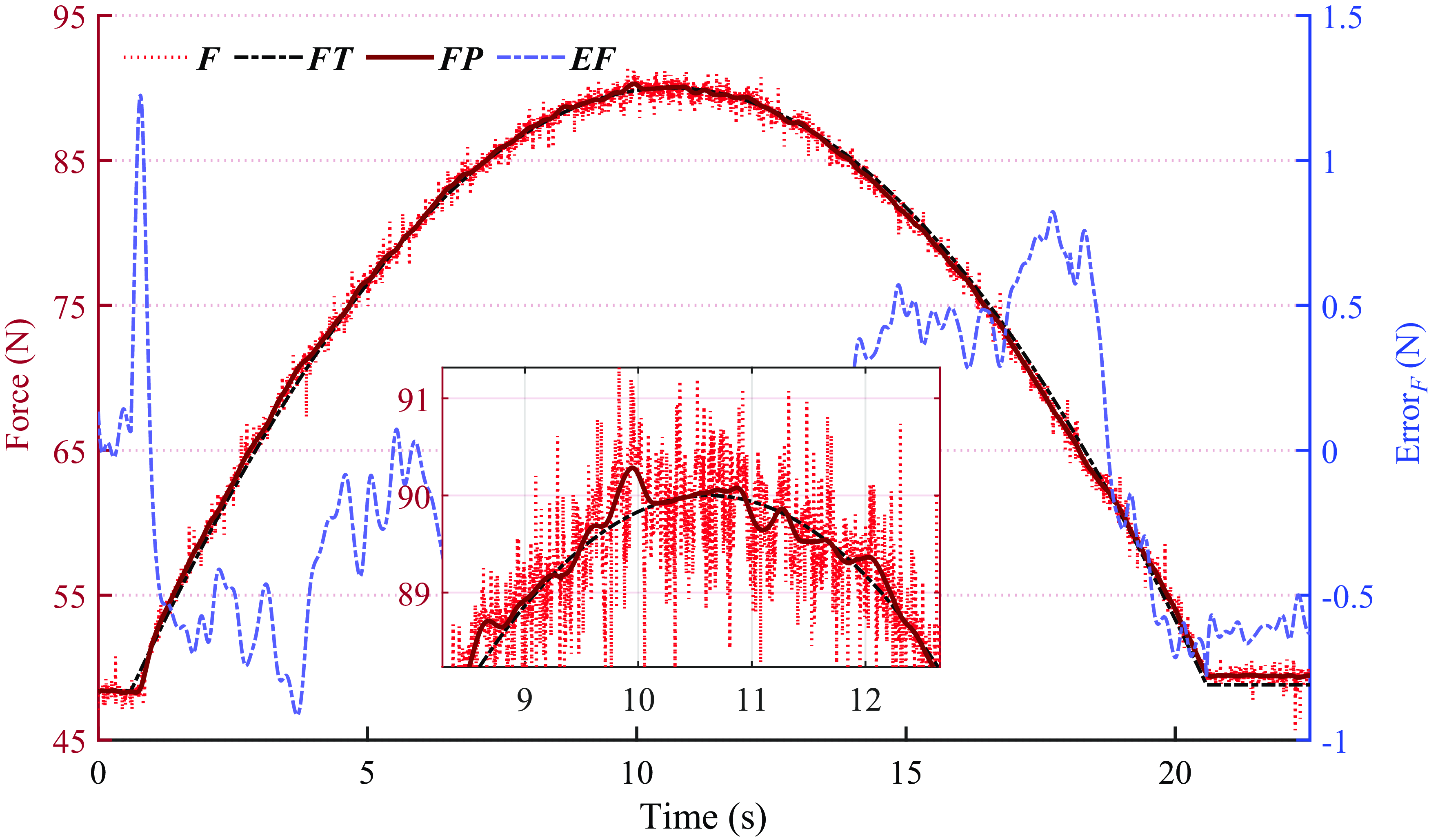
As presented in Figure 19, the maximum error in the Z-axis motion process of the four parallel cables lengths is approximately 1.99 mm. The source of the cable length error may be the elastic elongation of the cable itself and the exit point of the pulley, which is caused by position errors and structural errors of the robot. According to the spatial position X/Y/Z error curve in Figure 20, the Z-axis motion process has certain fluctuations in the X and Y directions. The maximum error is about 1.18 mm, the maximum error in the Z direction is about 1.09 mm, and the maximum error in the spatial position is 1.69 mm. In addition, the end effector has jitter in the X, Y, and Z directions, which is related to the motor motion control accuracy and the spring compression process. The spring length change measured along the Z-axis process by the force sensor installed on the spring axis is illustrated in Figure 21, and the spring stiffness is 1 N/mm. Based on the outcomes presented in Figure 21, the change in the forces provided by the spring is smooth. The average error is 0.36 N, and the maximum is 1.71 N, with no significant fluctuations or mutations during the movement. The changes in the forces of the four sets of parallel cables are smooth and continuous, without fluctuations and sudden changes in the cable forces, and have good motion stability.
The forces and errors of the spring of the Z-axis (F is the force of the sensor, FP is the filtered force, FT is the theoretical force, and EF is the error of force).

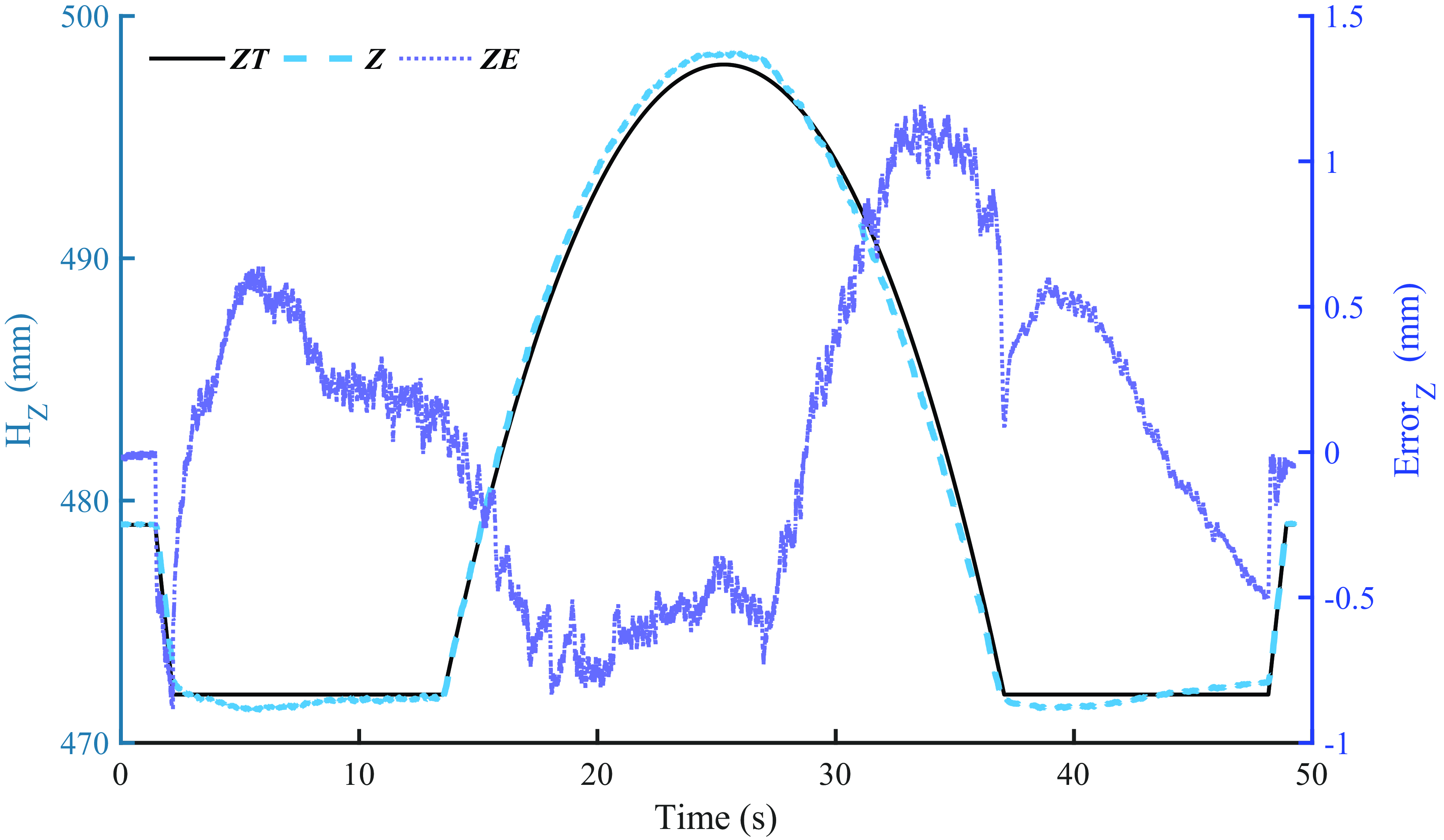
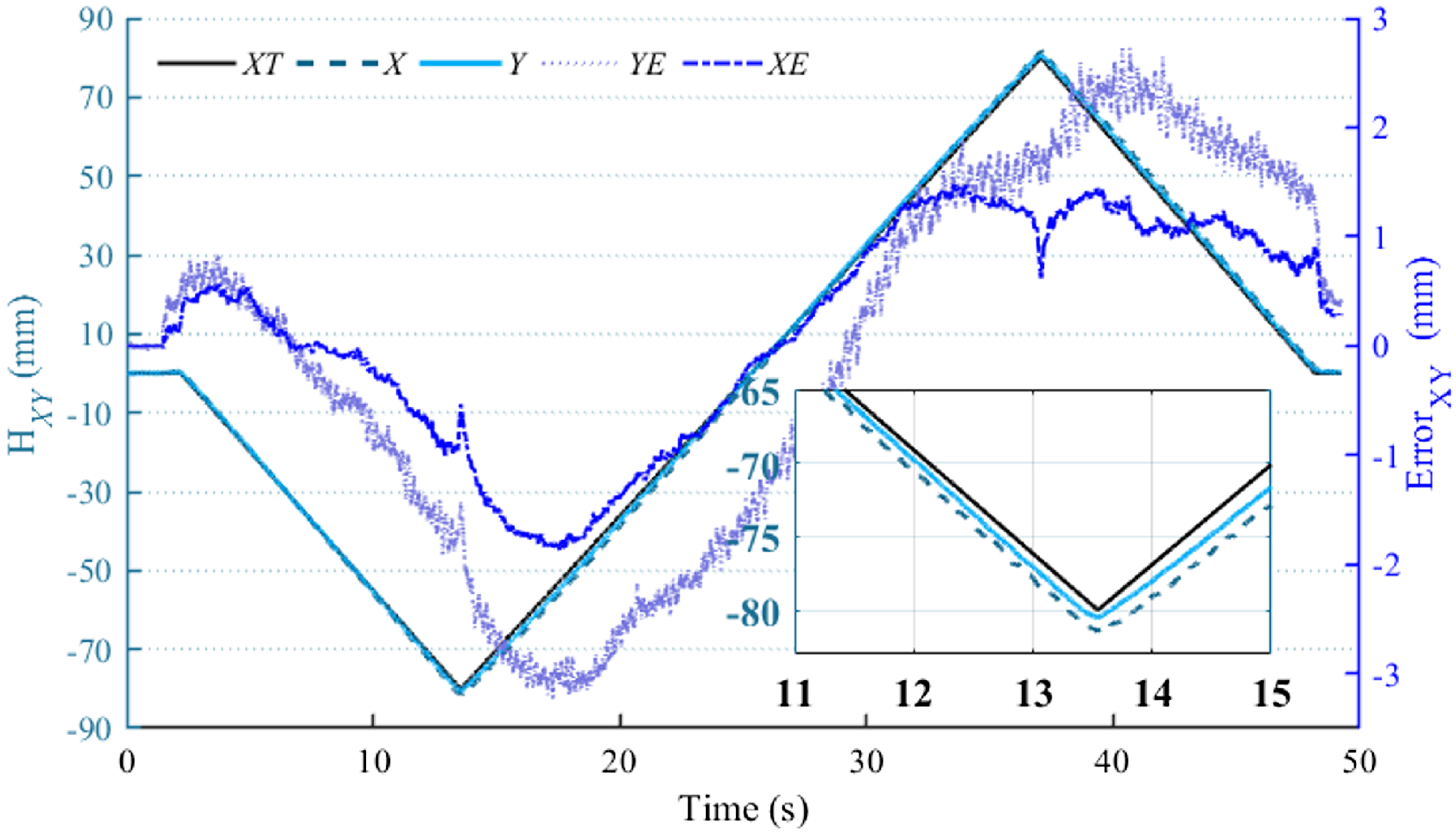
The three-point spatial arc motion of the end effector is carried out further to verify the motion performance of the designed RCDPR. The end effector’s starting position is set to (345, 345, 477), and the motion trajectory is to move in the negative direction along the Z-axis from the starting position 5 mm to Z = 472 mm, then pass through the arcs composed of three points (265, 265, 472), (345, 345, 498), and (425, 425, 472), and then move straight from (425, 425, 472) to (345, 345, 472). The movement speed is 10 mm/s, and finally, move straight along the Z-axis to the initial position. The spatial arc trajectory is shown in Figure 5. Figure 22 shows the change curve of the length of the four cables. The position of the center mark point of the end effector measured by the trinocular vision sensor is illustrated in Figure 23.
The lengths and errors of the cables of spatial arc.

The Z positions and errors of spatial arc (ZL is the theoretical position, Z is the position of the sensor, ZE is the error of position).

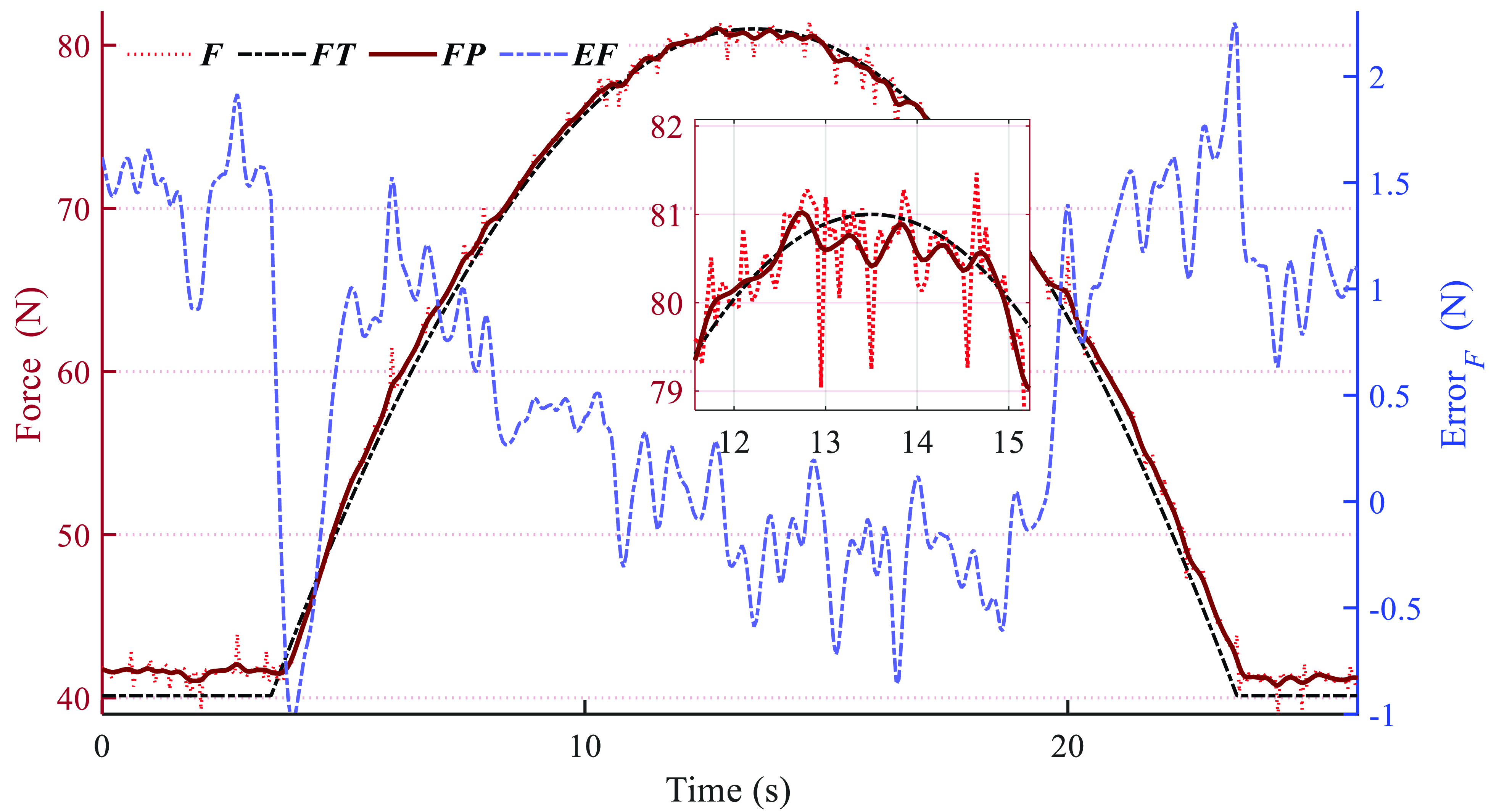
Since X/Y in spatial arc motion has the same motion information, Figure 24 only shows the theoretical value of X. The maximum error of the four parallel cables is about 2.38 mm, and the maximum error of the spatial position is 3.71 mm. The length error of cables in the spatial arc motion increases compared to the Z-axis motion. The maximum error in the X and Y directions is 3.22 mm, and the maximum error in the Z direction is 1.20 mm. It cannot be ignored that the error and jitter of the cables in the spatial trajectory relative to the Z-axis trajectory are relatively large. Experiments show that the cables’ jitter and the end effector’s vibration are more significant when performing complex spatial movements. Therefore, the RCDPR performs complex space operations, such as spraying, and further design-related vibration suppression algorithms are required to ensure the stability of the end operation. As presented in Figure 25, the maximum error of the spring force is 1.71 N, and the average error is 0.40 N. No large fluctuations or mutations occur during the movement, and it has good movement stability.
The X, Y positions and errors of spatial arc (XT is the theoretical position, X/Y is the position of the sensor, XE/YE is the error of position).

The forces and errors of the spring of spatial arc (F is the force of the sensor, FP is the filtered force, FT is the theoretical force, and EF is error of force).

5.3. Verification experiment of FFW
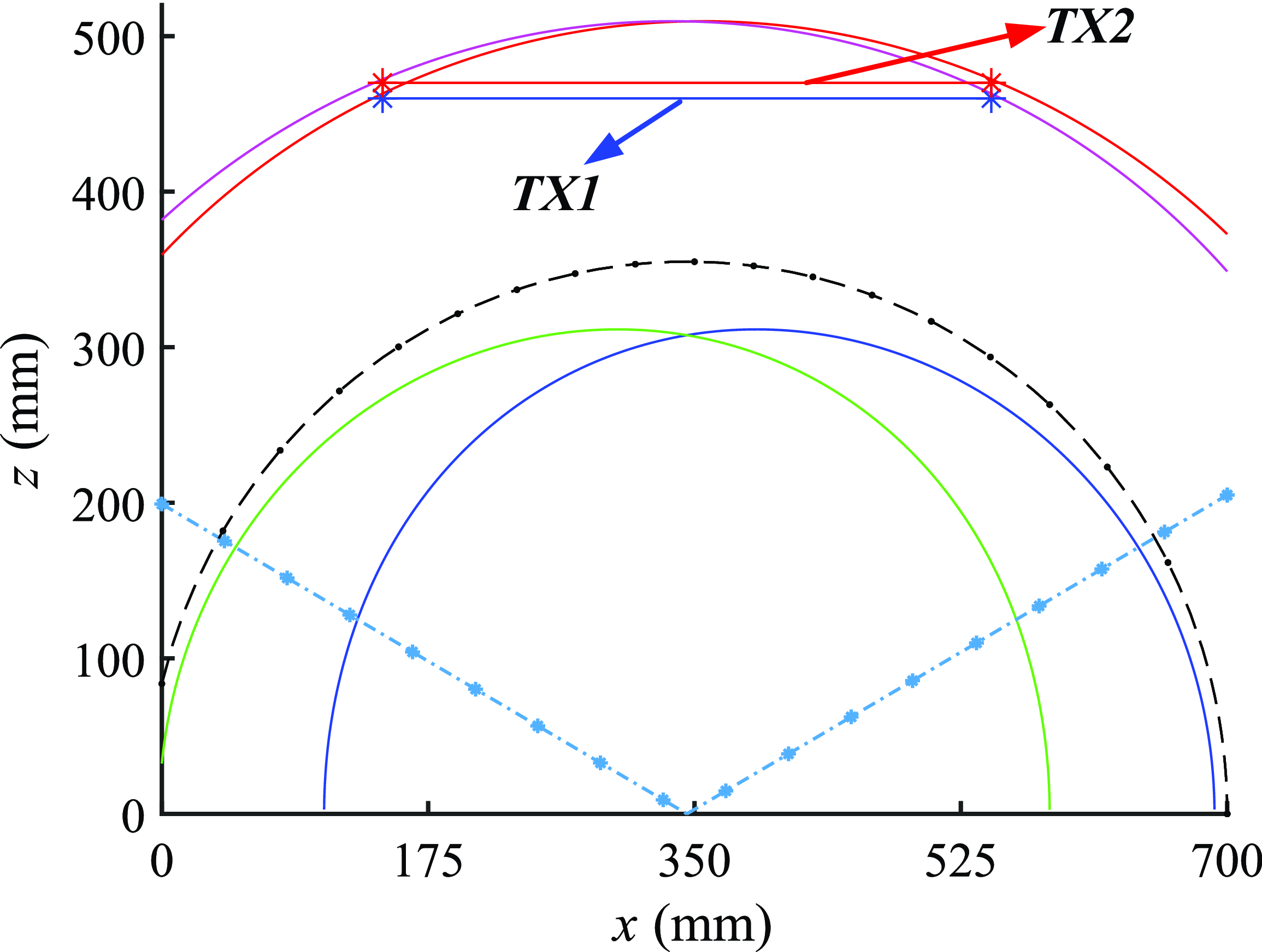
This section carries out linear motion at different positions in the X direction to further verify the designed RCDPR workspace boundary contour solving algorithm and analyze the cable lengths and position errors after the end effector moves out of the space boundary. The motion trajectory X1 (TX1) is set to start from the starting position (145,345,460) and move 400 mm in the positive X direction, and the movement speed is 20 mm/s. The motion trajectory X2 (TX2) moves 400 mm on a plane with a height of 470 mm, and the starting position is (145,345,470) outside FFW. The trajectories are shown in Figure 26.
The trajectory distribution of TX1 and TX2 in FFW.

As shown in Figures 27 and 28, in the TX1, the maximum error of the four parallel cables is approximately 2.03 mm. The maximum errors in the Y and Z directions are 0.84 and 1.62 mm, respectively. The maximum error in the X direction is relatively large, about 2.58 mm. The maximum error of the spatial position of the TX1 is 2.64 mm, and the overall motion accuracy is high. The spring force of the TX1 is shown in Figure 29. The spring also experiences force jitter during the X-axis movement, but its fluctuation is relatively small, with a maximum error of 1.23 N and an average error of 0.35 N. There are no apparent fluctuations or mutations during the movement, which shows that it is accurate and stable when moving within the FFW.
The lengths and errors of the cables of TX1.

The positions and errors of TX1 (X Y Z are the errors in the three directions, XL is the position of the sensor).

The forces and errors of the spring of TX1 (F is the force of the sensor, FP is the filtered force, FT is the theoretical force, and EF is the error of force).

As presented in Figures 30 and 31, in the TX2, since the starting point of TX2 is outside the FFW, there is a significant initial error of about 4 mm when the RCDPR moves to the starting position. From its visual position curve, the maximum position error in the X-axis direction of the starting position is about 6.68 mm. The cable length errors also increase rapidly when the end effector moves to the endpoint. Based on the outcomes presented in Figure 32, the spring force has a large error, with a maximum error of 2.25 N and an average error of 0.77 N. For the cable L2, the cable error increases from 0.5 to 4.5 mm in a short stroke, which is the same as the actual deviation measured by the spring force, and it changes rapidly. The reason is that when the end effector moves outside the FFW, some cables experience virtual traction and cannot maintain tension, resulting in a lack of force and position constraints on the end effector.
The lengths and errors of the cables of TX2.

The positions and errors of TX2 (X Y Z are the errors in the three directions, XL is the position of the sensor).

The forces and errors of the spring of TX2 (F is the force of the sensor, FP is the filtered force, FT is the theoretical force, and EF is the error of force).

As presented in Figures 30 –32, the maximum error of the four parallel cables is approximately 4.54 mm, the maximum error of the spatial position is 8.54 mm, and the maximum error of the spring force is 2.25 N. The force and position errors of the Z-axis, three-point arc, TX1, and TX2 trajectories are shown in Table 3, and the cable length errors are the average error. Comparing the trajectories TX1, Arc, and Z, it can be seen that the developed RCDPR has good motion accuracy and motion performance in FFW, and the designed FFW solution algorithm (BCA) has high accuracy and feasibility. The analysis of experimental results shows that the designed stability evaluation function can quickly optimize and reconfigure the structure of RCDPR, which has high practical guiding significance and application value. The BCA can realize the rapid design and optimization of the structure of the RCDPR with similar configurations and can be further applied to the real-time dynamic reconfiguration of the RCDPR.
Errors in spring force, end position, and cable length.

6. Conclusion
This paper presented the design and implementation of a redundant reconfigurable cable-driven parallel robot. The BCA solution process based on the positions of the hinge and spring was designed according to constraints such as structural limitations, operating environment, and external force interference. The analysis results demonstrated that BCA improved the accuracy and efficiency of solving FFW, and the computation time was reduced to 0.34 s. The stability evaluation function was established, which used FFW and MFW as carriers and stiffness and CFS as weights. Dimensionally unified and Gaussian-weighted designs were carried out to optimize the positions of the hinge and spring of RCDPR. After these evaluations, an experimental platform was established, and several experiments were carried out on the RCDPR prototype. The results demonstrated that the developed RCDPR had the advantages of high motion accuracy, ample workspace, and good motion performance. Moreover, through verification experiment of FFW, the measured results were found to be basically consistent with the theoretical analysis. These phenomena verified the accuracy of BCA for FFW and illustrated that the stability evaluation algorithm of RCDPR had high application value.
Future work can be carried out on other RCDPR structural parameters (e.g., spring stiffness and end effector size). The kinematics and workspace experiments of the reconfigured RCDPR and the design of dynamic reconfiguration strategies based on stability optimization can be further investigated.
Author contribution
Bin Zi conceived the formulations and the required mathematical methodology and then carried out the derivation procedure. Yakun Wang validated the formulations through the programming, drafted and revised the manuscript. Daoming Wang and Dan Zhang coordinated the research and helped revised the manuscript.
Financial support
This work was supported by the National Natural Science Foundation of China (Grant Nos. 52335002, 51925502).
Competing interests
The authors declare no conflicts of interest exist.
Ethical approval
Not applicable.
Supplementary material
The supplementary material for this article can be found at https://doi.org/10.1017/S0263574725000670