1. INTRODUCTION
“Function” is one of those words we use on a daily basis. We talk about the function of the heart being to pump blood around the body, and by analogy about functions in an organization, referring to a role or activity that something carries out. Mathematics has a clear definition of function in terms of a mapping from inputs to outputs. Vermaas (Reference Vermaas2010) identifies three archetypal engineering meanings of function: function as intended behavior of devices (e.g., Stone & Wood, Reference Stone and Wood2000), function as desired effects of behavior of devices (e.g., Lind, Reference Lind1994), and function as purposes for which a device is designed (e.g., Gero & Kannengiesser, Reference Gero, Kannengiesser and Gero2002). In our ordinary conversation, we rarely think about the exact meaning of the word, feeling confident in the use of our own languages. It is those vague everyday meanings of terms that we have to fall back on when we encounter the terms in a professional context.
The connotations of the word function are different in different languages. Germans speak of a machine functioning almost synonymously with the machine working. For example, the German use the verb funktionieren all the time colloquially as a synonym for working, as in “der Lift funktioniert nicht,” meaning “the lift does not work” (i.e., is broken), whereas the English meaning of “to function” more points to a purpose. For example, when an English person might say “the lift does not function” when it is running but might stop at the wrong place or not have the right capacity. Many native speakers of English intuitively draw a distinction between function (relating to purpose) and behavior (describing actions), which is central to the function–behavior–structure model by Gero and Kannengiesser (Reference Gero, Kannengiesser and Gero2002). By contrast, the German industry VDI Guideline 2221 on the “Systematic Approach to the Design of Technical Systems and Products” (Verein Deutscher Ingenieure, 1993) defines a function as a solution-neutral description of the relationship between input and output, which is an operation on material, energy, and information, and explicitly includes behavior in the definition of function. Shifting verbal intuitions is difficult for people and requires considerable training. In my experience, reading a definition once at the beginning, even if it makes sense, does not stick, and one reverts back to some intuitive meaning.
Function is a key term in engineering design methodology, as this Special Issue demonstrates with a rich history in German and English speaking methodology. As Goel (Reference Goel2013) shows in this Special Issue, many meanings of the term can coexist within a single line of research. Vermaas (Reference Vermaas2010) explains the range of different meanings that the term has in design research methodology. Although both these papers and other recent reviews, such as Crilly (Reference Crilly2010), provide a systematic account of the relation between different meanings of the word in different methodologies, the authors of those methodologies themselves show much less awareness of the debates that go on around the concept of function, which the Special Issue is hoping to elaborate.
This paper brings together experiences from interactions with engineers who are building or using functional models. Their modes of interaction with the models differ, as do their organizations, but all point to the conclusion that building and using functional models is not straightforward. Section 2 introduces some functional modeling approaches that are used in industry. Section 3 reports on two series of interviews in companies where designers talk about their use and understanding of function, as well as general issues associated with the introduction of new methods, which constitute a real barrier to bringing new functional modeling approaches to industry. Section 4 reports on an experiment with 20 graduate engineers, who had been provided with the same brief to analyze an existing product and identify its functions. The experiment shows the range of notions of functions the subjects had as well as the range of functional breakdowns that they produced. Section 5 reflects on the challenges around functional modeling as well as building models in general and argues that engineers want programmatic ways to build useful models rather than being caught up in theoretical discussions of the nature of function. Section 6 draws conclusions.
2. FUNCTIONAL METHODS USED IN INDUSTRY
Many academic methods involving functional model have been validated through industrial case studies, but academics generally struggle to introduce their methods successfully into companies. Many methods that are used have been developed by other companies and then publicized through academics, such as lean production (Womack et al., Reference Womack, Jones and Roos1990) or total quality management (Clark & Fujimoto, Reference Clark and Fujimoto1991), which were both developed at Toyota and described by researchers at leading US universities. This section introduces a selection of methods or approaches that are used in industry without any claim to completeness.
2.1. The challenge of method introduction
Some methods have been hugely influential on industrial practice. For example, the classic German product development methodologies, such as Pahl and Beitz (Reference Pahl and Beitz1977; Pahl et al., Reference Pahl, Beitz, Feldhusen, Grote, Wallace and Blessing2007) or Ehrlenspiel (Reference Ehrlenspiel1995), have been taught to generations of students and firmly instilled systematic product development thinking in companies. However, it is hard to judge to what extent these methodologies are followed in companies in terms of both the rigor and the completeness with which they are employed. These methodologies prescribe a sequence of steps that the engineers need to follow, producing particular types of models, to guarantee a successful outcome of their projects. How the methods can be applied in a specific context and how models can be developed for complex real-life cases rather than smaller teaching examples is left to the engineers' personal experience. This challenge has led to a certain method fatigue in general, which can be explained by the lack of flexibility and adaptability of many methods (Geis et al., Reference Geis, Bierhals, Schuster, Badke-Schaub and Birkhofer2008). The use of functional modeling has to be seen in this context.
2.2. Functional methods used in industry
Function is also an important concept in well-established methods used in industry, even though not necessarily with a crisp definition. For example, quality function deployment (QFD) was developed in the 1970s and 1980s originally in the Japanese shipbuilding industry but then widely published in the United States as a means to bring marketing and design closer together (Hauser & Clausing, Reference Hauser and Clausing1988). When functions are mentioned in Hauser and Clausing's influential paper, they refer to roles or departments in an organization; however, the paper implies that by applying the method, a high-quality working product will be developed through a systematic translation of customer requirements into engineering characteristics and then part characteristics, which in turn are mapped to key process operations and ultimately production requirements. Although very few companies follow the entire four-step process, QFD has now become an established part of modern business processes such as business process excellence or lean processes.
Many companies now carry out failure mode and effect analysis (FMEA), which identifies the potential failures and their likelihood and severity based on past projects, or failure mode, effects, and criticality analysis, which includes a rank ordering of the failure risks. A failure is defined as “the loss of an intended function of a device under stated conditions” (Langford, Reference Langford1995, p. 488). For example, a bicycle might fail to move smoothly. The failure modes are the ways in which the failure is observed (e.g., the bicycle has a flat tire), and effects are the “immediate consequences of a failure on operation, function or functionality, or status of some item” (e.g., the wheel does not turn smoothly). Knowing this is a risk, the designers can take a number of actions (e.g., having stronger rubber or a solid wheel to mitigate against the risk) or decide that the risk is acceptable. This is not a narrow or technical definition of function, but what is often interpreted as failure is when a product does not do what it is meant to do and the customer would get annoyed about it. Because designers need to mitigate against risk through the entire life cycle of the product, this is closely linked to design for robustness, which emphasizes resistance to damage and fit to environment, design for reliability, which is related to predictability and the ability to function within defined parameters, and design for resilience, which includes recoverability or adaptability in changing circumstances.
Another somewhat surprising meaning of the word function or functional is in the context of functional products (Alonso-Rasgado et al., Reference Alonso-Rasgado, Thompson and Elfström2004) in the context of a manufacturer selling a functionality rather than a product. For example, Rolls-Royce sells flight hours to some of its customers, whereby Rolls-Royce owns the engines, and services and maintains them, and the customer devolves the responsibility for looking after the product to the manufacturer. A very similar concept is expressed as a product-service system (Mont & Tukker, Reference Mont and Tukker2006), which emphasizes that the product and the process through which it is used need to be designed together.
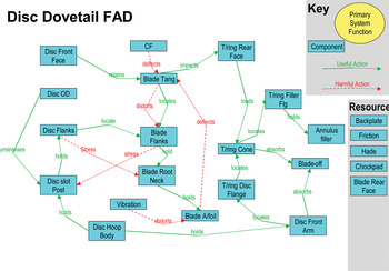
Many companies use TRIZ (e.g., Altshuller, Reference Altshuller, Shulyak and Rodman1999; for a review, see Hua et al., Reference Hua, Yang, Coulibaly and Zhang2006), which helps designers to identify conflicting constraints at the heart of design problems and uses solution principles elicited from an extensive review of Russian patents to resolve the conflict. The TRIZ vendors Invention Machine Corporation have patented a tool that allows graphical mapping of useful and harmful actions or effects between artifacts in a specialized form of concept maps, called functional analysis diagrams (FADs), describing artifacts, users, and other resources as nouns, and behavioral relationships as verbs. The key difference between FADs and function trees and function structures is that in FADs functions are intimately linked with the physical elements of a product rather than aiming for complete independence from physical form. Knott (Reference Knott2001) reports that TRIZ has been applied in Rolls-Royce for many years to resolve specific problems. For a long time, the company generated FAD diagrams in Microsoft PowerPoint, as illustrated in Figure 1.
An example of a functional analysis diagram (FAD) generated in Microsoft PowerPoint based on Bracewell et al. (Reference Bracewell, Gourtovaia, Moss, Knott, Wallace and Clarkson2009). [A color version of this figure can be viewed online at http://journals.cambridge.org/aie]

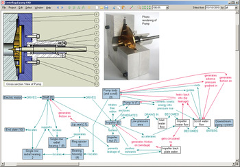
The FAD modeling has been taken up much more widely in the organization since a FAD diagram extension (see Fig. 2) has been developed for the DReD rationale capture system (see Bracewell et al., Reference Bracewell, Gourtovaia, Moss, Knott, Wallace and Clarkson2009; and in this issue, Aurisicchio et al., Reference Aurisicchio, Bracewell and Armstrong2013). The software was developed at Cambridge University in very close collaboration with Rolls-Royce. Because the company invested heavily, it embedded the software in its official company processes, offered training internally, and had company champions for the software. This enables a rare link between computer-assisted design (CAD) models and functional models, using an imported CAD file and superimposing a FAD model over it.
A functional analysis diagram (FAD) for a centrifugal pump. [A color version of this figure can be viewed online at http://journals.cambridge.org/aie]

Through PhD students entering companies, the contact and channel (C&C) approach developed at Karlsruhe University (e.g., Albers, Alink, & Deigendesch, Reference Albers, Alink and Deigendesch2008; Albers, Alink, Thau, et al., Reference Albers, Alink, Thau and Matthiesen2008; Alink, Reference Alink2010) is increasingly used in German-speaking companies. C&C models products through functions and the working surface pairs on which they take place. The core idea of the C&C approach is that function is only fulfilled when two components, systems, or products interact, through working surface pairs. The working surface pairs are connected through channel and support structures and have a physical location on the product. This ties product form and function intrinsically together, but it does not assign specific functions to specific components. Rather, it looks at functions and the working surface pairs where they take place at whatever level of detail is relevant, from the entire product to detailed features. C&C does not have a firmly defined concept of function, but it usually conceptualizes functions as creating, enabling, or suppressing behavior. The approach therefore lends itself to incremental design, because it supports the analysis of existing products as well as targeted improvements, where the designer can analyze exactly where a function takes place and how it could be modified or which new working surface pairs would be created by a modification and thus which effects or functions could occur.
3. OBSERVATIONS IN INDUSTRY
Engineers talk about functions in their daily working life. They have to describe that which is not form about a product, but their use of words is surprisingly loose, as is in some cases their understanding of exactly how form and function fit together. To illustrate some of these points, this paper draws on two case studies in which function was discussed in the context of discussing other methodological issues. Because the case studies touched on similar issues and deployed a mixture of notions of functions, they will be discussed together. The first case study was carried out in the summer of 2009 at a central European manufacturer of building tools. Interviews were carried out with six engineers at two sites to investigate the use of C&C in the context of general method introduction. The interviews were conducted in German; quotations were translated by the author. The second was carried out in 2011 in a UK diesel engine company on the role of virtual and physical testing. Again six engineers were interviewed. The author has worked with this company for years and is familiar with its overall processes and ways of working.
3.1. Introducing methods in companies
The UK diesel engine company is part of an American multinational, which tends to decide on methods used across the organization. The multinational works with consultants on introducing methods across all its companies. Because it is part of the automotive industry, it draws on methods used in the sector. The products are certified so that certain methods are part of the certification process.
The building tool company is independent and does not operate in such a tightly regulated sector. The company has hired method specialists with PhDs in product development, who are responsible for bringing new methods into the organization and supporting people in carrying out the methods. One of the method specialists commented on the general resistance to using methods in the organization:
There is always a spread, 30% of the people don't care, 30% are anyway against it, 30% are enthusiastic and simple accept such solutions… . The remaining 10% promote such things.
The challenge in method introduction for him lies in getting people to distinguish between the suitability of a method and how well people have used it. Methods need champions who help with a successful introduction at the beginning.
A method depends strongly on the people who carry it out. People who … don't know about development methods say the method does not work. This is simple, if I have somebody who tries to hammer a nail in a wall and hits his finger five times, he says the hammer does not work, but everybody would laugh and say you are too stupid to use a hammer. Applying methods is largely a matter of discipline. I have to discipline myself to use the approach and conventions of the method. This can particularly be a problem in creative areas, because people are worried that they lose flexibility through a method.
One of the engineers commented that learning a new method takes time and therefore can put a burden on the project on which the new method is first used.
3.2. Modeling and understanding functions
When the engineers in the tool manufacturer where asked about which methods they used in the company, they claimed that they would carry out functional modeling, building abstract top-down functional models in the Pahl and Beitz tradition. However, when they were asked for an example, the engineers were unwilling to volunteer an example. After some discussion, it emerged that they had several times attempted to build functional models but got stuck and abandoned the endeavor; they did not show us an example.
During the development of an innovative screw, they ran into problems, which they struggled to solve until they carried out a very systematic analysis of exactly how and where the functions of a screw were carried out. While they understood their product very well, they had not fully understood where and how vital functions, such as “cutting or displacing material,” were carried out. As explained in more detail by Matthiesen (Reference Matthiesen2011), they built detailed C&C models of parts of the screw, such as the tip or the thread of the screw, to see exactly which working surface carried out which function.
3.3. Incremental product development with known functions
It is not surprising that the screw development engineers did not know exactly how functions are carried out in their product in detail. They did not have to ask themselves this question previously, because at a high level both the purpose and the behavior of a screw are clear. More important, any new screw inherits some or all of its function from a previous generation of screws. Most engineering products are developed by modification from existing products, usually past designs created by the same company. Engineers are also well aware of competitor products and study related products to some extent.
Many engineering products have changed little in their basic functions over many decades, and the assignment of functions to systems is so stable that it is reflected in the organizational structure of the company. For example, the engine company has a piston group, a rotary components group, a gear group, and so on. The core expertise of the organization is tied up with designing components that provide known functions. While modern engine development is highly innovative (see Eckert et al., Reference Eckert, Stacey, Wyatt and Garthwaite2012), the pressure is toward achieving new requirements with minimal changes. Occasionally it is necessary to design a component from scratch. For example, the company designed a new configuration of a bracket for a generator where it systematically evaluated different configurations (see Wyatt, Reference Wyatt2011); however, the function was clear from the beginning.
One of the interviewees summarized this in the following way:
This comes back to what are our goals. We are an engine manufacturer. We are not going to produce a totally different power solution that is not an engine. That is not our goal. We start with this starting assumption. There are many different ways you can design an engine in a product and there are many different technologies you can add to this. Part of this is an engine. The abstract nature is kind of taken away.
3.4. Functions versus requirements
When the engine engineers were asked about an exact meaning of the term function, one of them provided the following answers.
We use . . . function in many different guises. When I use the word function I think of how we are organized, which is the functions of the business, which is totally different to the requirements, the functional requirements.
The company produces off-highway diesel engines, which are employed in a very large range of products from construction equipment to agricultural vehicles operating in most countries and climates in the world. The robustness and reliability of the products are key to their commercial success. Most of the design effort is directed to making sure that the engines will operate as required in all situations. Therefore, there are a very large number of requirements regarding what the engines need to do. The following dialogue from the interview exemplified the casual use of terminology in industry:
Interviewer: You talk about functional deployment and QFD also talks about function, but when one talks to [your] people, they never talk about function.
Eng1: [Nervous laughter] … I suppose it depends on how you want to define it in the letter of the theory. But I suppose we are all interested in function. Different functions of the engine, different functions of systems of the engine, different function of each component. It means something slightly different to all of the engineering community.
Interviewer: What actually is a function for you?
Eng2: A functional requirement can be anything. It can be an overall engine performance, fuel economy. Do we actually meet the requirements that the customer is looking for? If we go into the FMEA world, we can have functional requirements for every single component. The piston must withstand this environment; the engine must use … fuel. Those functional requirements get listed out in all our FMEA.
Interviewer: But these are just requirements, why are these functional requirements?
Eng1: Because they are requirements for the engine to meet this function.
It is just nonmenclature.
Eng2: We class it as a product function.
Rather than making a distinction among behavior, function, or performance, the engineers at the engine company lumped them all into the term functional requirement. The distinction is between functional requirements (i.e. what the engine does) and other requirements, mainly business requirements, such as costs or resource use requirements. Theoretically, functional requirements are concerned with what a product does and needs to enable the user to do, and the rest are nonfunctional requirements. However, the boundaries are blurred, because the nonfunctional requirements affect the functions (e.g., buying a cheaper material to meet a cost target would impede the robustness of the product and thus the functions). The diesel engine engineers are pragmatic. They use FMEA as a formal process of managing process risk, and listing a requirement as a functional requirement in the FMEA assures that it will be handled systematically.
Following the logic of FMEA, unwanted behavior of the engine is picked out as a potential failure mode against a specific functional requirement, for example, vibration would be a failure mode against several requirements, such as robustness. The tool designers thought of unwanted behavior as a type of disturbance (Störgrösse). For them function was “something positive.” Whether unwanted behaviors are seen as functions is closely related to the notion of function. In a behavior view of function, unwanted functions and desired functions are both functions. In a purpose view of function, an unwanted function cannot exist and becomes a disturbance. Designers are not necessarily consistent about this. The tool designers had no problem with the behavior view of function embodied in the C&C method and still did not use a concept of unwanted function.
The same broad meaning of function appeared again when the diesel engine engineers explained how they had developed a functional model for a QFD for the last generation of engines, which they have begun to reuse for other engines. Here the terminology points to the engineers assuming that performance arises from function, which is provided by the embodiment of the engine.
Interviewer: In the theory you would break down the function quite abstractly into what parts of the engine would do and from that get to an embodiment of the parts. From how you are talking about it, you have an architecture in mind and then characteristics of what these parts need to do … interesting that this slightly more abstract view of QFD does not seem to be necessary for you.
Eng1: You say that, but for [last generation] we tried to follow this. Saying we have an engine that has a set of functions to perform, deliver torque, etc. and then we break that down into functional systems. So within that you have a combustion system, a fuel system, a rotation system, etc. to map out the interactions between these systems. For example, in the combustion system you have influx, as well as pressure and temperatures. In the [last generation], we did a complete piece of work for these product characteristics how would you break down the engine into functional systems, and how these systems need to deliver, such that it all adds up into an overall engine performance. Then for those systems, what components exist in those systems and therefore what these components need to do to deliver this system function.
The engineers used the abstract function decomposition as a targeted exercise to force themselves to think abstractly about the product and how components and systems contribute to the delivery of the overall system function.
4. FINDINGS OF THE EXPERIMENT
The findings from industry show that the understanding of functions in companies is loose and divergent, without a clear definition of function or a consistent use of functional methods. This section reports on the findings from an experiment in which engineers were asked to analyze the same product individually, which showed that the notions of function used by individuals was as diverse as the functional breakdowns they generated to describe this product.
The experiment was carried out as part of an evaluation of the C&C approach. Because the C&C teaching at Karlsruhe explains the notion of function mainly through examples, the research aimed to contribute to a suitable definition for C&C as well as pragmatic ways of handling the concept of function. The following research hypothesis was investigated in the experiment: the way designers analyze a product is strongly influenced by their notion of function. This type of analysis requires rich data sets, and therefore the number of subjects that can be studied effectively is limited. A statistical analysis was never intended.
4.1. Methodology
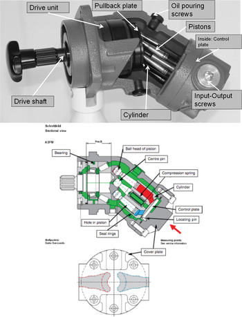
The task given to participants was to analyze a hydraulic pump used in off-road vehicles for lifting or moving heavy parts (e.g., the bucket of an excavator). This product was selected as an example of a design that is highly optimized for robustness and durability, and has sufficient complexity to reflect components that are designed by teams in industry. A more detailed explanation of the experiment can be found in Eckert et al. (Reference Eckert, Alink, Ruckpaul and Albers2011). Figure 3 shows the physical pump prepared for teaching, where the motor was replaced by a handle and part of the casing cut off, and a maintenance drawing of it.
A physical pump prepared for teaching and a maintenance drawing. [A color version of this figure can be viewed online at http://journals.cambridge.org/aie]

The subjects (18 male, 2 female) were all graduate mechanical engineers with between 1 and 30 years of professional experience. They had a similar academic background, being either trained at Karlsruhe in the last 8 years or else involved in teaching there. All but one (a Tunisian) were native speakers of German.
The first 11 subjects were given a physical example of the pump (Fig. 3). The subjects were permitted to manipulate the pump but not to dismantle it. Because certain aspects of how the pump works were hard to see on the physical object, it was decided to give the next 9 subjects a maintenance drawing of the pump instead of the physical pump, to avoid biasing the results through the use of one particular representation of the design, in terms of what subjects could see easily. It is well recognized that how designs are represented strongly influences design activities (e.g., Goldschmidt & Porter, Reference Goldschmidt and Porter2004).
The subjects were asked to explain the pump to one of the experimenters. To acquire a protocol that was as complete as possible, the experimenters asked the subjects what they were thinking or looking at in order to keep them talking and asked targeted questions to encourage them to fully explore the pump. While the experimenters might have biased the activity compared to a classical concurrent verbalization approach (see Ericsson & Simon, Reference Ericsson and Simon1993), the experiments yielded rich protocols, and the subjects commented that they experienced their explanations as a natural dialogue similar to a student coaching session.
The duration of the experiment was limited to 1 h. However, many subjects declared that they had concluded the task earlier, and they were therefore released. The experimenters discussed the outcomes after each experiment and provided feedback to the subjects at the end of the experimental period. The experiment was videorecorded. The experiment was conducted in German. All functions and other results of the experiments have been translated to English by the author as literally as possible.
4.2. Analysis of the data
The audio recordings were transcribed. The transcriptions of the 20 experimental protocols consisted of between 3,000 and 5,000 words each. All sketches were transformed into a standardized tree format to express the written functions. The verbal protocols were used to identify when the subjects talked about functions but did not write them down. These verbally described functions were then added to the function trees based on the context in which they were expressed. The analysis of the function trees concentrated on the following issues:
• written versus spoken functions,
• the level of abstraction of the expression of the function, and
• the level of detail in the analysis.
This was related to the notion of function that the subjects had provided in the prior interviews or at the end of the experiment.
A statistical analysis of this data would not be appropriate due to the small total number of subjects and the lack of even distribution between the different groups. With a sample size of 20, the margin of error would be 21.9% for a confidence level of 95%.
4.3. Outputs generated in the experiment
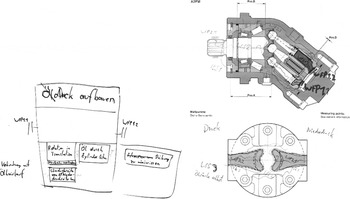
This section provides a picture of the outputs of the experiment. All but 1 subject wrote down at least one function. The most obvious difference between the two groups was that the subjects who were given the two-dimensional schematic drawing did not sketch aspects of the product, whereas 10 out of 11 subjects in the other group drew sketches to understand or illustrate parts of the pump. The subjects using the maintenance drawing pointed out and marked the subsystems that carried out the functions they were speaking about, whereas all but 1 of the subjects using the pump made sketches to point out the subsystems whose functions they were discussing. Figure 4 shows a typical output from a subject given the maintenance drawing. On the left-hand side, the function tree, drawn as a box representation, can be seen, with subfunctions arranged inside the box of the main function. The right shows accompanying annotations to the maintenance drawing.
A typical representation of a maintenance drawing subject.

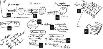
Figure 5 shows a typical sketch produced by a subject who was given the pump. He created additional drawings to clarify aspects of the pump. On the top left-hand side of the figure, the main function of the system, the Hauptfunktion (stated in d), is broken down into three subfunctions. These functions correspond to the sequence of the pumping operation: a, draw in oil; b, convey oil; and c, dispense oil/create pressure. To understand the piston movement, he created a sketch of one piston in different positions (a, b, c). As soon as the sketch was created, he identified further functions at a lower level of detail, for which he did not produce more sketches but instead wrote down the functions (g, position drive unit; h, lubrication). Part f shows the arrangement of the pistons that draw in oil and dispense oil, two functions that occur sequentially, which makes him aware of the need to position the piston cylinder. Part j refers to the function of support the revolver and part i refers to lubrication, which is a function on a lower level in the function hierarchy, because it supports all other functions of the pump. The arrow from the upper drawing (see f to j in Fig. 5) indicates a detailing of the analysis.
An example of an analysis by a subject provided with the physical pump. The pump functions correspond to the sequence of the pumping operation: a, draw in oil; b, convey oil; c, dispense oil/create pressure; f, draw in oil and dispense oil; g, position drive unit; h, lubrication; i, lubrication (which is a function on a lower level in the function hierarchy, because it supports all other functions of the pump); and j, support the revolver. HF, Hauptfunktion, the main function.

4.4. Variation in the functional breakdowns
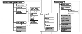
On average, each subject identified 11.3 functions (written plus verbalized), ranging from 1 to 17 (see Eckert et al., Reference Eckert, Stacey, Heisig, Clarkson and Vajna2010). Figure 6 shows three function trees with very different number of functions, levels of detail, and ratio of spoken to written functions. (The spoken functions are shown in italics on a grey background, and connected with dotted lines.)
Three function trees of different depth and detail.

The greatest agreement was around functions generic to all pumps. However, many subjects missed generic subfunctions, such as lubrication and sealing. A number of additional functions are required to suppress the undesired behavior of some components. For example, the shape of the sealing plate and the pin that holds the cylinder in place both exist to stop the cylinder from misaligning and thus generating leakage. However, to identify these functions, the subjects needed to understand in detail how the pumping mechanism works, and several of them were not able to do so.
At the end of the experiment, most subjects claimed that they had now understood how the pump worked. Most subjects stopped before the allocated time of 1 h was over, yet some subjects indicated that they would have concentrated on the casing or the drive mechanism if more time had been available.
4.5. Different notions and expressions of function
Fourteen subjects had been interviewed prior to the experiment about their experience with C&C and asked about how they would define function; the remaining subjects were asked after the experiment.
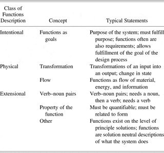
Table 1 gives an impression of the range of answers. The middle column lists the key concepts, and the right columns elaborate the flavor of the answer. The partial nature of the answers reflects the subjects' statements.
Range of notions of function provided by the subjects

To a certain extent, the answers mirrored the distinction of Vermaas (Reference Vermaas2010) into “intentional definitions,” which are typically expressed as “what the product does” (akin to an action description) or “what the product is meant to do” (implying a particular goal), and “physical descriptions,” covering transformations and flows. However, many subjects responded with a syntactic definition saying how a function should be phrased rather then what a function was. The subjects who used syntactic notions expressed their understanding of a product through the convention they attempted to adhere to. For example, one participant, when thinking about lubrication, could not figure out whether this was matter (something physical), information (concerned with the relationship between parts), or energy, because he was not sure whether the pump was self-lubricated, and therefore whether the lubrication fluid could also transmit energy.
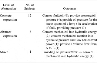
All subjects agreed that the main function of the pump was pumping the oil. Two subjects mentioned that the pump could also be a motor that transforms the flow of oil into a rotation. Table 2 illustrates the range of phrasing and the level of abstraction for the main function of the product.
Different expressions of the main function of the pump

Many subjects indicated that they were unsure whether to name the main function as “pumping oil” or “pumping fluid.” Some changed oil to fluid and vice versa. Others referred to the oil or medium or liquid in the course of the sessions. Ten subjects used a verb–noun pair when writing down a function. Others subjects even used verb–noun pairs to describe functions verbally. The two most experienced subjects had no problems with expressing functions as verb–noun pairs.
4.6. Different approaches to functional decomposition
Subjects adopted different strategies to analyze the product. The following classification is based on the analysis of the protocols and in some cases a discussion with the subjects. The following strategies have been identified:
• Top-down (four subjects): Subjects analyzed the overall system and proceed to further levels of detail. The focus became more detailed step by step.
• Important things first (two subjects): Subjects focused immediately on what they perceived as the main function of the most relevant subsystem. The criteria for the decision were not explicit. The focus was chosen arbitrarily or based on experience.
• Issue driven (seven subjects): First the subjects created an overview and then detailed specific issues, which seemed important to understand or which they found problematic. They tended to write functions down as they went along.
• Power flow throughout the system (seven subjects): Subjects followed the power flow from the source of the power to interfaces with other parts of the system. The flow starts where torque and rotational motion come into the system through the drive shaft. The rotation is then used to move the pistons in order to draw in and dispense the hydraulic oil.
The study revealed a very personal and fluid notation of function and a number of strategies that did not appear to be related to the notion of functions. The subjects were genuinely surprised to find that their way of doing a function analysis was not universal. The experiment did not prove or disprove the hypothesis it started out with, nor did it reveal a predominant way to carry out a C&C analysis, rather it pointed to the need for clearly and repeatedly practiced function analysis approaches.
4.7. Subjective understanding of the pump
As soon as the subjects saw the pump, several commented that they knew how it worked. As they began analyzing it, they realized that while they might have known in general how pumps worked, they did not understand the details of this pump. However, when at the end of the experiment the subjects were asked whether they understood the pump now, all responded that they did. However, the function trees show that the understanding is partial, and in many cases the subjects had made actual mistakes. Several of the subjects also commented through the experiment that they had now understood how the pump worked. However, when they were subsequently asked what a particular component or feature did, they realized that they had not fully understood it. While they all claimed that they had understood the pump, their understanding was partial and different judging from the different function trees that they produced. None of the subjects drew a distinction between function and behavior in discussing the functions of the pump. Even those subjects who had a goal or a purpose view of function did not consider behavior as a separate category. Some of them had particular problems with conceptualizing unwanted behavior and, in consequence, knowing how to handle in functional terms the features of the pump that were targeted at suppressing unwanted behavior. This showed that the participants' notion of function influenced the way they analyzed functions. However, the experiment did not show whether a particular notion of function led to better or more in-depth analyses of the pump.
Creating a functional breakdown was not easy or comfortable for many of the subjects, because they realized that they could not find the location where the function they had hypothesized would be carried out or they could not see the role a particular feature played. For example, several had difficulties in seeing where the oil comes into the pump, and the product subsequently did not make sense to them. Even when they were guided to an answer, their sense of frustration lingered. Even the subjects who had not made mistakes sometimes had difficulties in
• understanding the role of features and components in the overall function;
• phrasing of functions;
• assigning functions to places in the function tree;
• describing aspects of the products, such as sealing or lubrication, which applied to several high-level functions or components; and
• recovering from mistaken assumptions about how the product worked.
It also became clear that the confusion around the concept of function was detrimental to a consistent application of C&C. Alink (Reference Alink2010) concluded that designers need to be guided through a set of pragmatic questions, such as “What does the component do?”, “What is happening at this working surface pair?”, and “Where is the second working surface pair to fulfill a function?”
5. CHALLENGES OF USING FUNCTIONAL MODELS
The interviews and the experiments have revealed that designers use different notions of functions as required by the context in which they are working with specific models like QFD, Pahl and Beitz, or C&C models being deployed for a specific purpose. This section explores some of challenges associated with functional modeling regardless of a specific modeling approach. Challenges in functional modeling arise both from the concept of function and from the nature of models.
Both the industrial interviews and the experiments indicate that designers in industry do not have a clear concept of function and mixed many issues, such as behavior, purpose, and performance, and met requirement, under the single term function. Building models without clear concepts is very problematic. Modeling can be problematic for designers and managers in many situations where the mapping between the model and the target of the model is not entirely clear or habitually defined. This is especially the case with modeling design processes (Eckert & Stacey, Reference Eckert, Stacey, Heisig, Clarkson and Vajna2010).
The participants in both the interviews and the experiments were graduate engineers. They had been trained in product development methods during their degrees and will have had a certain exposure to academic methods involving functions. The participants did not comment on why they did not pick up a clear understanding of function during their design education. However, during another interview series, a young engineer once commented to the author how much he regretted not having paid more attention to methodology training at university. At the time, he was just interested in the technology and had not gathered experience with projects. Now that he has to manage things, he really would like to know.
5.1. The trouble with models
Designers build many models and interact frequently with models, but they rarely think about what a model is or can give them. They frequently use CAD models, which describe the form of a component with the underlying assumption that a component will be built according to the geometry defined in the model. With the CAD model, it is clear to the designers what aspects of the product are or are not included in the model. They describe geometry and have properties associated with this geometry. CAD models can be simulated to reveal the behavior of the product or component under certain circumstances. However, at present, the link between the geometry and the intended function cannot easily be represented. Performance models are mathematical and have a very clear range of relationships incorporated in them.
However, assessing how closely a model describes its target (the object or process that it models) is in general far from simple. The relationship between a model and its target is fundamentally analogical, requiring the construction of a mapping between dissimilar things that have similar combinations of relationships between their parts (see Holyoak & Thagard, Reference Holyoak and Thagard1996). Giere (Reference Giere2004) points out, referring to work by Sua'rez (Reference Suárez2003), that it is not the model that represents reality but the scientist using the model by exploiting similarities between the model and reality and making selections about what they include. Teller (Reference Teller2001) puts this as, “We make something into a model by determining to use it to represent.” Models both isolate aspects of reality and idealize reality (Mäki, Reference Mäki2011). The philosopher Roman Frigg (Reference Frigg2003) explains representations in terms of three relations: denotation, display, and designation: “A model denotes its target system in roughly the same way in which a name denotes its bearer. At the same time it displays certain aspects, that is, it possesses these aspects and a user of the model thematises them. Finally, an aspect of the model designates an aspect of the target if the former stands for the latter and a specification of how exactly the two relate is provided.”
From a practical perspective, this relates to challenges designers generally face with models:
Selection: Models are produced from a particular viewpoint for a particular purpose. Without these being explicit, the user of a model does not understand the rationale of the person who built the model. This is clearly an issue with functional models, around both the scope of the model and the notion of function. For example, whether unwanted functions (e.g., vibration) are included in a functional model depends on the view of function. In the experiment, many subjects were unsure how to handle issues such as lubrication or sealing. Clearly the system needed to be sealed and lubricated. Some ignored these in their functional decompositions, even though they had thought about them during the product analysis; others mentioned lubrication as a function, but did not connect it to other functions; and some added lubrication as a top-level function.
Abstraction: Models can be generated at different levels of abstraction, which influence the range of objects they denote. As many design methodologies, such as Pahl and Beitz (Reference Pahl and Beitz1977; Pahl et al., Reference Pahl, Beitz, Feldhusen, Grote, Wallace and Blessing2007), request abstract functional models independent of the embodiment, many of the subjects in the experiment aspired to abstract models, without being quite aware what this meant. For many, this expressed itself in the struggle to find the right phrasing. This is linked to the purpose of a model. If a model serves for a particular analysis, as in the case of the screw, this problem might not arise, but often the ambitions behind functional modeling go beyond an individual product to a whole product family, leaving the designers with the challenge of knowing what specific characteristics to include or not to include. Therefore designers do not have a real sense of how “true” or accurate the model is. In the case of the engine, the basic functionality has changed very little, and the designers know the functions of components and systems and can draw on this knowledge to build a model. They created an abstract model built using their generic experience of engines. The engine company has experts who have a not only very deep but also broad understanding of their products (Flanagan et al., Reference Flanagan, Eckert and Clarkson2007). Most products are based on existing products; building a functional model for such an incrementally developed product requires understanding the starting product very well, really knowing the roles of specific features in the product, which as the experiment showed is not easy, but also defining the function of the new parts.
Utility: Designers in industry need to see a merit in both creating and using functional models. In the case of the diesel engine designers, they build functional models because they understand the benefits of QFD and are strongly incentivized by their organization to apply QFD successfully. The tool designers built a partial functional model when they had run into a problem and needed to understand exactly how and where a function was carried out in a product. Designers need an incentive to build functional models, and this needs to be clear to them before they begin to build a model. The benefit of model building lies in
1. the understanding gained through the process of the model building,
2. the results gained through building the model, and
3. the knowledge that is captured in the model.
The designers who build the model must see personal benefit in the model building. Although the reuse of the model is of benefit for an organization, it is difficult to encourage designers to do modeling well without this. They might try because they are requested to build the models, but they are more likely to give up when they run into problems.
Expressing models: Many engineering models, such as CAD models, have clear modeling conventions and tools with which to express and interpret the models. This does not generally exist for functional modeling. The diesel engine engineers we encountered used spreadsheets to write down functional models. This makes it hard for them to modify and maintain the models. Models that are generated in an ad hoc fashion are often only clear to the person who generated them.
5.2. The trouble with functional modeling approaches
Many of the problems designers have with functions, however, do not arise from the notion of function as such but from the challenges of applying particular functional modeling approaches. The position papers by Vermaas (Reference Vermaas2013) and Goel (Reference Goel2013) show the plethora of different functional modeling approaches, many of which rarely reach people in industry. However, even if they do, people in industry can find them hard to apply.
Modeling approaches in textbooks and academic papers are usually illustrated with examples, such as hair dryers, which illustrate different elements of the models well but are far smaller in scale than many of the products that the designers are working on. A diesel engine or an entire car are far more complex. Having a complex product requires a way of expressing a big model or focusing on particular aspects, which requires drawing clear system boundaries around aspects of the product or producing high-level models that hide detail in a principled manner. These decisions themselves can be hard for designers.
Some modeling approaches require a particular level of abstraction in their model, for example, instructing designers to express functions independently of the embodiment of the product. The methods are designed to force designers to break free from existing preconceptions of the product to enable them to come up with innovative solutions. However, this is still hard for designers who are used to thinking about specific products with specific functional decompositions. As the example of the diesel engine company shows, this often goes deep into the organizational structure of the organization. Failing to break free from an existing product structure gives the designers the impression they have failed in carrying out the modeling.
Modeling approaches are often better suited to one class of problems than another, for example, for mechanical systems rather than for mechatronic systems, or for new product development as opposed to incremental design, making it difficult for designers to apply them to their particular problem and situation. Many of the functional modeling approaches are embedded into wider systematic design approaches, and the designers feel that unless they follow every step of the whole methodology, their individual models are worthless. However, they often do not have the time to follow a whole modeling approach. While the prescription is intended to help them, it can also be very offputting to designers. Designers can also be put off by the terminology used in the different modeling approaches. Not only might the concept of function be explained in ways that they are not familiar with but also the terminology that they use to explain functions can be difficult.
5.3. Summary: What the designers want
Designers want easy to follow methods that they can understand without a huge learning effort. They want to see a fairly immediate benefit to applying the methods to their own work. For functional modeling, it is important that designers enjoy the modeling and get something out for themselves in terms of their own understanding. If they need to learn a modeling approach, because it is not intuitive, they need training materials that are clear and intuitive. The explanations need to help them to deal with exceptions (e.g., lubrication) and difficult situations (e.g., mechanical to control interfaces). They need a clear way to write their models down and understand the models that they have generated. A model that is difficult to read in the end is also often difficult to build. Designers do not want to use modeling approaches that make them feel guilty or inadequate. In functional modeling, this is particularly an issue around functional models that are closely linked to an existing product structure.
The lack of consistent application of functions modeling illustrates that none of the current functional modeling approaches have become a prevailing paradigm for functional modeling and meet these criteria of easy to learn and easy to apply. While some modeling approaches are easier to learn than others, modeling inherently requires training and effort. Engineers need to accept that they will have to invest this effort into learning a functional modeling approach well and practice applying it. This requires training students in functional modeling at university. It also requires persistence with functional modeling in industry, for which engineers need to recognize the benefit of building the models and negotiating their meaning with each other. This involves investing time in particular in early stages of the design processes, which is difficult to justify for individuals unless functional modeling is incentivized by the organization and anchored in the company processes.
6. CONCLUSIONS
The case studies presented in this paper illustrate that function is for most engineers a fluid concept, where the same word has very different meanings depending on the context at the intersection of company jargon, academic methods, and intuitive everyday meaning.
Function is a problematic concept for practicing designers. They have to describe that which is not form about a product and do not have easy and intuitive ways of doing so. Rather than being able to adopt and apply a coherent and explicit definition of function, designers fall back on their everyday language understanding of function. Reading a definition of function at the beginning of a paper or a training session is not enough to change people's notions; they need systematic training to adopt a particular view, which than becomes hard to unlearn. Adopting a specific functional modeling approach is a considerable commitment and effort and needs organizational support and persistence. Designers in industry are most likely to use functional modeling if it is part of established approaches, like QFD or FMEA, which are applied across their industry sector and are pushed through the formal processes in their organizations. While both methods advocate an integrated design approach, they are in practice mainly used to generate requirements and therefore structure processes, rather than for design synthesis tasks. At present, functional modeling largely stands outside of the tools and methods that designers use to adapt, generate, or analyze new designs. Functional modeling is not well integrated with CAD system or design analysis software, nor are there obvious procedures for closing this gap.
Functional modeling has the potential to act as a means to integrate different groups in an organization who usually work in different object worlds with their own representations and modes of thinking. For example, system engineers who integrate mechanical and electrical design with software design use functional breakdowns of products to understand the need for integration and identify interfaces. Testing engineers plan and carry our tests of products against product requirements, but they also need to understand under which circumstances a component for a system needs to carry out a particular function. Engineers who plan and design product platforms need to be aware of functions shared across multiple products. However, none of these groups can usually refer to a common model.
There is little evidence that the rich academic debate around function is recognized in industry. Therefore designers miss out on much of the benefit they could gain from thinking in functional terms and building functional models. If they create functional models, they need tools and training to do so, as the example of the FAD models shows. Rather than rigid prescriptions, they need pragmatic ways of handling concepts that show them a benefit. The rich meanings of the term function are complementary, and designers drift through different meanings from purpose to flow or behavior. In teaching them about functions, it might be an exposure to that richness they would benefit from most, both in terms of the views on function and the places in design processes functional thinking would be beneficial.
ACKNOWLEDGMENTS
I am grateful for the assistance of our industrial collaborators, especially the engineers and managers we interviewed and observed. I acknowledge the enormous contribution of my collaborators at KIT, in particular Thomas Alink, who is now manager of engineered systems at Micos GmbH. This research has benefited from conversations and feedback from Martin Stacey, De Montfort University. In particular, I thank Rob Bracewell, University of Cambridge and Imperial College London, for providing me with a DReD FAD and for discussing tools for functional modeling with me.
Claudia Eckert is a Senior Lecturer in design at Open University, the British distance education university, where she also carried out her doctoral research on design processes in the knitwear industry, before spending nearly 10 years in the Engineering Design Centre at University of Cambridge. Her research interests are in understanding and supporting design processes and in particular engineering change and processes planning. Dr. Eckert is also working on comparisons between design domains.