1. Introduction
With the rapid development of computer science and unmanned systems, human-computer interaction has been developing in a more natural and universal direction [Reference Kandemir and Kose1]. Traditional ground station (GS) [Reference Liu and Durrani2] and remote control [Reference Ahmed, Zaidan, Zaidan, Salih and Lakulu3] control methods are gradually unable to meet the needs of complex tasks, especially when performing precise control in dynamic environments, the limitations of a single sensor are particularly obvious. How to achieve stable, reliable, and flexible control of drones by fusing multiple sensor data is the current research focus. Vision-based drone control uses visual odometers and simultaneous localization and mapping (SLAM) algorithms to achieve autonomous navigation using environmental features, but its performance in low-texture or dynamic environments is limited and has high computing requirements [Reference Arafat, Alam and Moh4, Reference Zhuang, Zhong, Xu, Tian and Yu5]. Through the control method of integrating vision and gesture sensors, computer vision can recognize gestures in the current image and convert them into control commands for the drone to achieve precise control of the drone. However, this method has high requirements for computing resources and the equipment is relatively bulky, making it difficult to widely popularize [Reference Li, Liu, Wang, Zhang, Qiu, Zhao, Zhou, Cai, Ni and Cangelosi6]. However, gesture recognition technology has gradually become a hot trend in human-computer interaction for unmanned systems. Through gesture recognition technology, users can use gesture commands to control the flight operations of unmanned systems, providing a more flexible, efficient, and convenient control method for drone flight control.
In recent years, gesture recognition and gesture pose estimation have been widely studied with the continuous development of applications such as sign language translation and gesture control [Reference Ojeda-Castelo, Capobianco-Uriarte, Piedra-Fernandez and Ayala7, Reference Chen, Yu, Tu, Lyu, Tang, Ou, Fu and Xue8]. Gesture recognition tasks are divided into two main categories: vision-based gesture recognition [Reference Wang and Tao9] and sensor-based wearable gesture recognition [Reference Galván-Ruiz, Travieso-González, Tejera-Fettmilch, Pinan-Roescher, Esteban-Hernández and Domínguez-Quintana10]. Although vision-based gesture recognition makes telecommunication more intuitive and does not require physical contact, vision-based gesture recognition has a blind spot and wearable gesture recognition perfectly avoids this drawback. In addition, the hand joints have more degrees of freedom, and the human hand can make a variety of complex and different gestures, which greatly increases the difficulty of hand characterization for visual gesture recognition [Reference Mohamed, Mustafa and Jomhari11]. In addition, sensor-based wearable gesture recognition has been widely studied due to the low cost of sensors applied to detect hand gestures, as well as the fact that most of the drawbacks of visual-based gesture recognition can be overcome [Reference Amin, Rizvi and Hossain12–Reference Fang, Sun, Liu and Liu16]. Flexible sensors have the advantages of high accuracy, fast response, multimodal sensing, and high reliability in gesture recognition, making them an ideal gesture recognition technology that has attracted much attention. The principle of data gloves designed based on Fiber Bragg Grating (FBG) sensors is that an optical fiber will pass through all the hands, Bragg structure at a specific point as the finger joints, and through the response of the sensors, information about the angle of the joints can be retrieved, and can provide digital data about the angle of the hand posture in real time, but the manufacture of FBG sensors requires the use of special optical fibers, which are very expensive and in a large range is not very applicable [Reference Perez-Ramirez, Almanza-Ojeda, Guerrero-Tavares, Mendoza-Galindo, Estudillo-Ayala and Ibarra-Manzano17]. A flexible resistive curvature sensor is used in ref. [Reference Setiawan, Ariyanto, Munadi, Mutoha, Glowacz and Caesarendra18] to accomplish the measurement of the angle of the finger site for subsequent gesture recognition. Both flexible fiber optic sensors and flexible resistive bending sensors have good advantages, but a single-finger curvature sensor can only accurately measure the information at the finger, which has the limitation of not being able to measure the information at the hand. The data glove designed in ref. [Reference Hwang, Lu and Lin19] was based on an inertial sensor incorporating accelerometers, gyroscopes, and magnetometers. Although it could accurately measure the finger motion information, subjects were limited in using wired transmissions with great inconvenience when they were performing hand function assessment tasks. Later in ref. [Reference Fei, Xian, Xie, Wu, Yang, Yin and Zhang20], researchers used a six-axis inertial sensor for data glove design and adopted Bluetooth as the wireless transmission protocol, although the defects of wired transmission were solved, the lack of magnetometers and the increase of sensor data with time will carry a certain bias. In addition, data gloves based on multi-sensor fusion are also being widely studied, and a wireless smart glove is introduced in ref. [Reference Connolly, Condell, Sanchez and Gardiner21], which is designed to perform accurate measurement of finger movement by integrating multiple inertial sensors and customized control algorithms. In ref. [Reference Sarwat, Sarwat, Maged, Emara, Elbokl and Awad22], a data glove based on 10 flexion sensors, 5 mechanical sensors, and 1 inertial sensor is proposed to collect informative data on patient’s movement, collect and send the data to a web-based mobile application and machine learning algorithms for an automated assessment system for home rehabilitation.
Although sensor-based glove applications for human-computer interaction are relatively mature, there are some shortcomings. Firstly, the sensor data acquisition device and the gesture recognition device are separated, and the data acquisition is carried out at the glove side, while the gesture recognition is carried out at the computer side [Reference Ullah, AbuAli, Ullah, Ullah, Siddiqui and Siddiqui23, Reference Barioul and Kanoun24]. This recognition method will bring some problems, firstly, it needs to build the communication link between the glove side and the computer side, which is prone to packet loss and can not guarantee the stability of unmanned aerial vehicle (UAV) control; secondly, because the glove side and the recognition side are operated separately, it is not very convenient to use it in some occasions. In addition, many sensor-based data gloves have high accuracy for static gesture recognition and very low accuracy for continuous dynamic gesture recognition [Reference Kim, Lee and Shin25, Reference Jeon, Choi, Noh, Kim and Lee26]. Convolutional neural network (CNN) is a technique based on statistical learning theory, which can be well applied to data feature extraction and can be used to classify a variety of complex gestures in human-robot interaction [Reference Watanabe, Chen, Komura and Ohka27] and to implement a real-time gesture recognition system human-robot interaction [Reference Liu, Luo and Ju28]. Xu’s research team [Reference Xu, Yu, Xiang, Zhu, Hussain, Liu and Li29] proposed a novel SE-CNN architecture algorithm for myoelectric sensor-based gesture recognition, which introduces time-squeezing and excitation blocks into a simple CNN architecture and then uses it to recalibrate the weights of the feature outputs of the convolutional layer, effectively improving the accuracy of gesture recognition by enhancing important features while suppressing useless features. Park’s team [Reference Park, Chandrasegar and Koh30], in order to improve the accuracy of the gesture recognition algorithm, combined 2D-FFT and CNN in their research, which can improve the accuracy of human-computer interaction by using ultra-wideband radar to acquire image data, then transforming it using 2D-FFT and importing it into CNN to complete classification Meanwhile recurrent neural networks (RNNs) are widely used for time series processing and many studies have been done to achieve recognition of dynamic gestures based on its variant Long Short Time Memory network (LSTM) [Reference Mekruksavanich and Jitpattanakul31–Reference Zhang, Xue, Lan, Zeni, Gao and Zheng33]. Hu et al [Reference Hu, Gong, Chen and Han34] proposed a long and short-term memory (MIC-Attention-LSTM) algorithm utilizing the maximum information coefficient attention mechanism to improve the effectiveness of gesture recognition, firstly, using the correlation number to reduce 10 time-domain features, and then selecting 5 features to create the optimal set of features, and then employing the MIC to establish various reduction thresholds, classify various combinations of channels, and determine the various signals correlations between channels, compared with the LSTM model, after completing the feature and channel approximation of EMG sensors, the classification accuracy of the MIC-Attention-LSTM model is improved by 9.47%, and the results show that the Attention Mechanism algorithm is able to effectively highlight the weight of the key signal sequences and improve the classification accuracy of the LSTM.
Although the above gesture recognition method can improve the accuracy of gesture recognition, there are still some problems. First, due to the large arithmetic requirement of the above model algorithm, after completing the training on the PC side, it cannot be realized to run in the embedded processor with limited resources, and the gesture recognition control can only be completed on the PC side or the server side, which requires the construction of a communication link between the wearable console and the PC side, which is susceptible to packet loss, and cannot ensure the stability and real-time of the control of the UAV. In addition, since the sensory data acquisition and gesture recognition tasks are operated separately, that is, the sensory data acquisition is completed at the wearable device end and the gesture recognition task is completed at the PC end, it is not convenient to use in some occasions. Therefore, this study designs a multi-sensor fusion data glove based on STM32 microprocessor, which achieves comprehensive capture of the whole hand gesture information by integrating and fusing flexible fiber optic sensors and inertial sensors, and deploys a dual-network gesture recognition method based on the Keras framework to the STM32 processor using the X-CUBE-AI plug-in that is included in the STM32CubeMX. Realize the integration of hand gesture posture data acquisition task and gesture recognition task at the data glove end, and finally complete the data glove control experiment of UAV in the simulation platform and real scene.
In summary, this paper designs a wearable data glove based on multi-sensor fusion for UAV control. Firstly, the data glove scheme design is carried out in Chapter 2, including sensor selection and hardware circuit connection design. Next, the definition of static and dynamic gestures, as well as the processing and acquisition of sensor data, are carried out in Chapter 3, and the construction and training of the gesture recognition model are carried out in Chapter 4. Finally, model porting and simulation validation are carried out in Chapter 5.
2. Data glove program design
The hardware structure of the data glove is shown in Figure 1, which consists of three parts: sampling unit, processing unit, and communication unit. Among them, the sampling unit includes inertial sensors and flexible fiber optic sensors, the process of which is to attach the sensors to the back of the finger hand, and obtain the sensor data of different hand postures through the corresponding communication method; the processing unit includes a power supply battery, a data storage and a core processor, in which the power supply battery is used to drive the entire circuit, and the core processor is used to drive the entire system and to store the acquired sensor data; the communication unit includes a communication interface and a UAV, and the communication interface is used for external communication, and is connected to the UAV through MAVlink.
Data glove hardware structure.

2.1. Core processor module
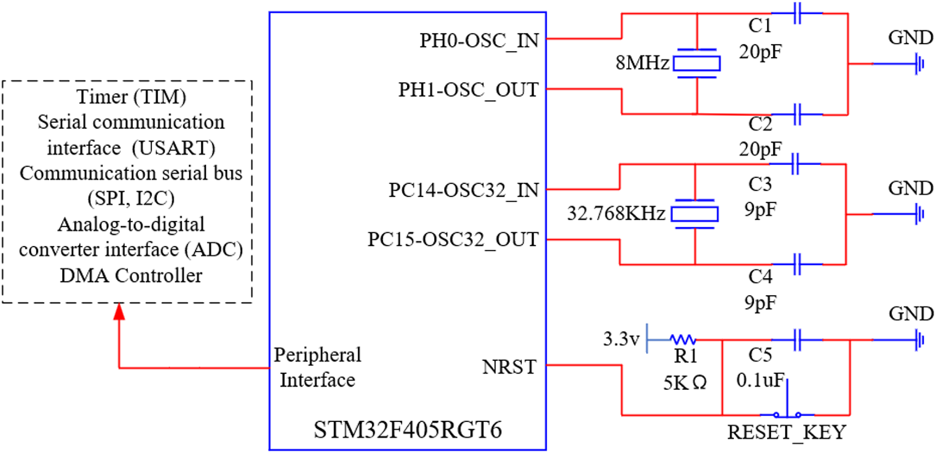
The core processor module of the data glove designed in this study selects the advanced processing chip from ST‐STM32F405RGT6 microprocessor, which is equipped with the Cotex-M4 high-efficiency engine in the ARM core architecture, supports a variety of communication modes, such as SPI, I2C, and USART, and has a built-in general-purpose timer (TIM), DMA controller, and 12-bit analog-to-digital converter (ADC). The peripheral resources of this microprocessor chip are shown in Figure 2, and it fully meets the needs of the data glove application in terms of the implementation of peripheral communication interfaces.
STM32F405RGT6 microprocessor peripheral resources.

STM32 microprocessor peripheral crystal circuit design principle is through the use of crystal and capacitors to form a parallel oscillation circuit, the crystal through the vibration, you can generate accurate and stable clock signals for driving the microprocessor, the oscillation frequency of the crystal and the capacitance of the capacitor is related to the capacitance of the crystal, in order to ensure that the generation of stable clock signals, the selection of 20 pF capacitance to match with the crystal of 8 Mhz, and the selection of 9 pF capacitance and the crystal of 32.678 Khz. 8 Mhz crystal to generate a stable clock signal for the circuit, so that the microprocessor has a main frequency of up to 168 Mhz, and at the same time has 1 M Flash memory and 192 KB SRAM, which enables the embedded artificial intelligence module of X-CUBE AI to smoothly execute complex artificial neural network model, and thus improve the ability and accuracy of the recognition of various action commands. This enables the X-CUBE AI’s embedded AI module to smoothly execute complex artificial neural network models, thereby improving the ability and accuracy of recognizing various movement commands and ensuring real-time responsiveness of the UAV’s maneuvering process. In addition, the microprocessor also provides rich software development tools and support, such as CubeMX, keil5, etc., which is convenient for developers to carry out software development and system integration, and fully meets the needs of data glove applications in terms of gesture recognition implementation.
2.2. Peripheral communication module
The data glove designed in this study captures the motion attitude information of the finger and hand by fusing the flexible fiber optic sensors and JY901S data and uses the AS14 module to complete the acquisition of sensing data and the sending of UAV control commands, and the hardware communication connection of the data glove is shown in Figure 3.
Data glove hardware communication connections.

2.2.1. Flexible fiber optic sensors
For finger curvature detection, Flex Sensor and Fiber Optic Flex Sensor are widely used. Flex Sensor calculates the resistance of the sensor by adjusting the resistance value of the internal variable resistor, which is then mapped to the angle change, while Fiber Optic Flex Sensor changes the intensity of the internal fiber optic and converts the light intensity into an electrical signal, which is then mapped to the sensor’s deformation angle by calibration fitting. The electrical signal is then mapped to the angle of deformation of the sensor through calibration fitting. A comparative analysis of the performance of the two sensors is shown in Table I.
Through the above comparative analysis, this study selects the flexible fiber optic sensor to be applied in the design of the data glove for accurately measuring the degree of deformation of the finger and the change of movement, the flexible fiber optic sensor communicates with the STM32 microprocessor through the five channels of the analog-to-digital conversion module ADC and the structure is shown in Figure 3. Flexible fiber optic sensor by the light source LED, optical fiber, and sensing head composition, its internal can be regarded as a transistor, the base corresponds to the light source, when the sensor deformation occurs, the intensity of the light source inside the sensor will be changed, the emitter is responsible for the internal light intensity signal is converted into an electrical signal output, but the sensor output of the electrical signal accompanied by the presence of noise, so the use of the sensor output by
 $\mathrm{R}_{0}$
,
 $\mathrm{R}_{1}$
, and
 $\mathrm{C}_{1}$
composition.
 $\mathrm{R}_{1}$
and
 $\mathrm{C}_{1}$
amplification filter circuit composed of the output signal filtering and amplification processing, so that the voltage value obtained in the ADC acquisition terminal is stable and reliable, where
 $\mathrm{R}_{1}$
and
 $\mathrm{C}_{1}$
constitute a high-pass filter, used to filter out the low-frequency components of the output signal,
 $\mathrm{R}_{0}$
is used to set the amplification multiplier, and finally through the microprocessor’s ADC analog-to-digital conversion channel to complete the acquisition of the output voltage, the flexural acquisition circuit of the fiber optic sensor is shown in Figure 4.
In order to more accurately collect the curvature of the finger in the gesture, this study uses a double-layer finger ring to fit the flexible fiber optic sensor tightly to the finger. In order to prevent the double-layer finger ring from causing the fiber optic sensor to bend, the flexible fiber optic sensor is not completely tightly wrapped on the finger. The starting position of the sensor, that is, the end with the acquisition interface, is placed between the mid-phalangeal phalanx and the proximal phalanx, and the end position of the sensor is placed between the distal phalanx and the fingertip. Since the length of the flexible fiber optic sensor is a fixed value, when placing the sensor, adjust the position of the flexible fiber optic sensor to cover the mid-phalangeal phalanx and the distal phalanx. As shown in Figure 5.
2.2.2. Inertial sensors
The inertial sensor in the data glove uses JY901S module, which supports serial communication protocol and I2C communication protocol. The module integrates high-precision gyroscope, accelerometer, and geomagnetic field sensor, using high-performance microprocessor and advanced dynamics solving and Kalman dynamic filtering algorithm [Reference Liu, Hu, Su, Wei and Qin35], which can quickly solve the module’s current real-time motion attitude, the measurement accuracy of static 0.05 degrees, the dynamic 0.1 degrees. Because of its attitude collection accuracy and data calculation performance, the quaternion attitude data calculated by the inertial sensor is used as the gesture attitude data.
Comparison of flexible sensors.

Flexible fiber optic sensor acquisition circuit.

Flexible fiber optic sensors place hand information.

The hand posture sensing device needs to have the ability to detect multiple types of hand posture, but the flexible sensor can only measure the curvature of the distal and middle phalanges of the fingers, and the position of the proximal phalanges can not be measured. In order to ensure the flexibility of the control, an inertial sensor is placed in the proximal phalanges of each finger. The specific placement of inertial sensors in the data glove designed in this paper is shown in Figure 6. An inertial sensor is placed in the main board of the back of the hand, corresponding to ⑥ in the figure, which is connected to the main control chip through serial communication and is used to sense the rotational attitude of the hand in the whole space; since the thumb has only two degrees of freedom, distal phalanx, and mid-phalangeal phalanx, the inertial sensors are placed in the mid-phalangeal phalanx of the thumb and the proximal phalanx of the other fingers, respectively, corresponding to ①, ②, ③, ④, and ⑤ in the figure, through the DuPont wire terminal in the form of I2C communication with the main control chip connected, and before using the five sensors need to be configured with the device address, in order to use the software I2C for addressing data acquisition.
Inertial sensors place hand information.

By fusing flexible fiber optic sensors with inertial sensors, the details of gesture recognition can be optimized. Flexible fiber optic sensors can accurately measure the deformation and movement changes of fingers. Between the middle phalanges and the distal phalanges of the fingers, the use of flexible fiber optic sensors can realize the recognition of the single degree of freedom of finger bending. However, the proximal phalange gesture recognition is not a single degree of freedom but involves the recognition of three degrees of freedom of roll, pitch, and yaw of a single finger, so inertial sensors are required to complete the acquisition of the three degrees of freedom. As shown in Figure 7, the five sensors at the finger joints can be used to sense the more refined spatial rotation gestures of each finger, increase the flexibility and diversity of gestures, and due to the additional inertial sensors at the finger joints, the gestures that originally represented one meaning can be expanded to two meanings, so adding inertial sensors can enrich the effect of gesture recognition. However, if inertial sensors are all deployed on the middle phalanx, distal phalanx, and proximal phalanx, although the accuracy of gestures will be increased, resources such as the degree of freedom of acquisition will not be fully utilized, resulting in a waste of inertial sensor acquisition resources. It cannot solve the problems of high performance required by the processor core, high production cost of data gloves, and complex operation and control of drones. In summary, the method of fusing flexible optical fiber sensors with inertial sensors can not only improve the accuracy of gesture recognition but also reduce the required processor core performance and production costs.
Comparison of the extension of gestures.

2.2.3. Communications unit
The data glove designed in this study aims to realize real-time, stable, and safe control of the UAV in a special environment. In order to satisfy the manipulator’s ability to control the flight of the UAV in real time and to ensure the safety of the manipulator, the data glove should have the ability of long-distance communication. For this reason, this study selects the AS14 module with 2.4 Ghz as the communication unit of the data glove, which is based on the Global System for Communication, General Packet Radio Service technology, and Transistor-Transistor Logic (TTL) level serial data transmission, supporting multi-frequency communication and different rate transmission, with the baud rate set to 57,600, and the maximum transmission distance of 1800m can be realized. The maximum transmission distance of 1800m can realize wireless data transmission and remote communication. The USART communication connection between AS14 module and STM32 microprocessor is shown in Figure 3.
2.3. Power module
The power supply module, as the driving core of the data glove, needs to have high stability and load capacity. For this goal, this study designed the power supply circuit, and the circuit schematic diagram is shown in Figure 8. The power module of the data glove consists of a 3.7 v lithium battery, a USB interface, a j5019 boost module, a TP4056 charging chip, and a voltage regulator. A 3.7 v lithium battery, USB interface, and TP4056 linear constant voltage charging chip constitute the charging circuit of the power module, in which the 3.7 v lithium battery supplies power to the data glove, and the TP4056 linear constant voltage charging chip has a constant current charging and over-voltage protection. With constant current charging, over-voltage protection, and other advantages, the USB interface input 5v voltage can be converted to 4.2 v voltage for the lithium battery charging. j5019 boost module and voltage regulator components constitute the power module boost circuit, in which the j5019 boost module can be the lithium battery input 3.7 v voltage boost to 7 v. In order to provide a stable voltage for the subsequent voltage stabilizing components, the subsequent voltage stabilizing components use LM1117S-3.3 and LM1117S-5.0 to ensure that the data gloves are provided with stable 3.3 v and 5 v voltages. Meanwhile, in order to solve the problem of possible current overload in the power module, a Schottky diode is installed at the input of the voltage regulator element to avoid this situation. In addition, adding a 10uF electrolytic capacitor at the input of the voltage regulator element helps to store energy and significantly reduces noise interference at the power input; however, since large capacitors are less effective in filtering high-frequency signals, a 0.1uF filter capacitor is attached to the output of the regulator to form a two-stage filtering system, thus greatly reducing the noise caused by the regulator’s voltage conversion fluctuation.
Power supply circuit.

For the implementation of hardware circuits, the reasonableness of PCB layout, alignment line width, component spacing, power supply, and bottom line alignment methods is the key to determining the overall performance. The PCB3D diagram and the data glove physical diagram are shown in Figure 9.
(a) Data glove PCB 3D drawing; (b) Data glove physical drawing.

3. Gesture definition and sensor data acquisition scheme design
Safe, reliable, and convenient human-computer interaction has high requirements for achieving high recognition rates of gesture recognition and scientific gesture sets. In addition, simple and easy-to-operate gesture definitions and reasonable sensing datasets play a vital role in the design of the data glove.
3.1. Gesture definition
The definition of gesture includes static gestures and dynamic gestures. A static gesture is a stationary gesture that alone represents a semantic meaning. Dynamic gestures refer to a sequence of two or three gestures and transitions between gestures that together represent a semantic meaning. The addition of inertial sensors at the abduction and adduction degrees of freedom of the five fingers allows for the definition of more gestures.
The definition scheme of static gestures refers to ten Arabic numerals gestures and some gestures of twenty-six English alphabets, in addition to adding custom gestures and so on to reach a total of 32 kinds of static gestures (one of which indicates no gesture), as shown in Figure 10. Some of these gestures are easy to operate, easy to understand, easy to remember, and very consistent with the lightweight gesture action analysis method required for UAV gesture control.
Static gesture definition. Dynamic gestures are defined by transforming between two static gestures.

3.2. Sensor data acquisition and processing
Highly accurate and robust hand pose recognition algorithm models are trained based on a large number of valid datasets. Therefore to address the two problems due to the high dependence of hand pose capture on inertial sensors and the fact that inertial sensor data in space can change due to the movement of the hand in space. We have designed a spatially omni-directional hand pose data capture scheme to ensure that the trained neural network model is robust to spatial omni-directionality.
Gesture data acquisition steps.

3.2.1. Sensor data acquisition
The scheme of gesture acquisition is shown in Figure 11, taking one gesture as an example, each gesture acquisition process includes 7 steps, and 5 samples are acquired in each step, and 35 samples are acquired in total. In the acquisition process, we take the position and direction of the glove adaptation as the center position of the acquisition, and then follow the following steps:
-
a. Horizontal direction: firstly, rotate 90° to the left to collect, rotate the collection center position 90° to the left and collect data; secondly, rotate 90° to the right to collect, rotate the collection center position 90° to the right and collect data;
-
b. Up and down direction: firstly, rotate 90° upward to collect, rotate the collection center position upward by 90°, and collect data; secondly, rotate 90° downward to collect, rotate the collection center position downward by 90° and collect data;
-
c. Rotation direction: rotate 90° clockwise for acquisition, rotate the acquisition center position 90° clockwise, and acquire data;
-
d. Spatial direction: draw a semicircle upward to the right for acquisition, draw a semicircle upward to the right of the acquisition center position, and acquire data; followed by draw a semicircle downward to the right for acquisition, draw a semicircle downward to the right of the acquisition center position, and acquire data.
With the above data acquisition scheme, we can obtain data samples of the hand posture in the spatially omni-directional case, which ensures that the trained neural network model is robust to spatial omni-directionality.
According to the above acquisition scheme, we carried out the design of the data acquisition method based on Unity visualization, the interface of which is shown in Figure 12, and mainly includes the example gesture display module, the sensor data display module and the data acquisition module. The example gesture display module includes gesture selection and gesture display functions. By clicking the gesture selection drop-down box, you can select the gesture to be displayed. After clicking the display button, the interface will display the example image of the selected gesture. Here, the example gesture is the hand shape on the left side of the figure; the sensor data display module is used to real-time display of sensor data from the STM32 processor sent through the AS14 digital transmission; The data acquisition module is used to save and organize the sensor data information acquired from the sensor data display module and automatically tag it. For the convenience of the data acquisition process, we map the example gesture switching to the left and right keys on the keypad, and map the sampling to the space bar on the keyboard, so that the example gesture switching and data sampling operations can be carried out more quickly.
Unity data collection visualization interface.

In this study, the hand gesture data of 21 volunteers were collected, and a total of about 25,000 pieces of data were collected. The gender, hand length, and hand width of the volunteers were recorded during the collection process, and the distribution of the data volume was divided and analyzed according to the different hand widths, hand lengths, and genders of the collectors, respectively, as shown in Figure 13.
Distribution of data.

Sensor electrical signal output fitted to the deformation of the measured finger.

3.2.2. Sensor data processing
By consulting the official documents of the flexible optical fiber sensor, it can be seen that the flexible fiber optic sensor internally adopts the optical sensing technology to convert the light intensity signal into an electrical signal output, which results in a nonlinear relationship between the electrical signal output from the sensor and the degree of deformation of the finger. In order to more accurately process the signal output from the sensor, it is necessary to complete the data calibration fitting for the nonlinear characteristics of the sensor, so this study through the data glove will be flexible fiber optic sensors attached to the finger. Firstly, the acquisition of the finger in the horizontal state of the electrical signal output value, which is calibrated to 0°, and secondly, the acquisition of the finger in the clenched fist state of the electrical signal output value, which is calibrated to 90°, and then through a protractor to measure the bending angle of the finger. By measuring the finger bending angle, and at the same time record, the corresponding bending degree of the electrical signal output value, and finally complete the finger bending angle and the corresponding electrical signal of the calibration of the fitting analysis, as shown in Figure 14, the fitting coefficient
 $\mathrm{R}^{2}$
reaches 0.989, the fitting effect is good, the fitting formula is shown in Equation (1).
 \begin{equation} \text{Angle }=\left(-486.75\right)\times \mathrm{V}_{\mathrm{out}}^{3}+575.31\times \mathrm{V}_{\mathrm{out}}^{2}-204.07\times \mathrm{V}_{\mathrm{out}}+25.69 \end{equation}
where
 $\text{Angle}$
is the finger deformation angle and
 $\mathrm{V}_{\mathrm{out}}$
is the voltage value collected by the microprocessor ADC.
Each time the data glove is powered on and initialized, the analog-to-digital conversion channel of the microprocessor ADC will obtain the voltage after amplification and filtering of the flexible optical fiber sensor. The collected voltage value can be converted into the corresponding finger bending angle through the calibration fitting formula (1). As shown in Figure 15, the nonlinear curvature from the middle phalanx to the fingertip is measured. When the finger bending degree is 0°, the collected voltage value is approximately 0.5, when the finger bending degree is 10°, the collected voltage value is approximately 1.6, and when the finger bending degree is 60°, the collected voltage value is approximately 2.1. The collected voltage value is converted into finger deformation, which can be used to complete the construction and recognition of the subsequent gesture data set.
Flexible sensor bend calibration.

Inertial sensor Z-axis initialization flow.

In inertial sensor data acquisition, direct reading of Euler angle data from inertial sensors may encounter gimbal deadlock problems [Reference Ji, Wang, Ma, Feng and Li36]. When the second axis of the Euler angle is rotated by plus or minus 90 degrees, it loses the degree of freedom of one axis, resulting in an unnatural interpolation between the two orientations. Therefore, in this study, quaternions are used for attitude solving instead of Euler angles. Although quaternions are more abstract in terms of understanding and Euler angles are more intuitive, they provide more accurate and efficient attitude information in terms of computation. In addition, inertial sensors commonly suffer from Z-axis drift, which is due to the fact that the Z-axis data is highly affected by the magnetic field, and the Z-axis data varies each time the power is turned on and activated, even under the same placement orientation. Therefore, this study adopts a software initialization scheme for Z-axis angle. The initialization of the Z-axis can be achieved by using the conversion between quaternions and Euler angles [Reference Jahanchahi and Mandic37], which converts quaternions to Euler angles according to Equation (2) and Euler angles to quaternions according to Equation (3). This allows more accurate acquisition of attitude information and solves the Z-axis drift problem. The initialization of the Z-axis is shown in Figure 16.
 \begin{equation} \mathrm{A}=\left[\begin{array}{c} \text{atan}\mathrm{2}\left[2\left(\mathrm{q}_{0}\mathrm{q}_{1}+\mathrm{q}_{2}\mathrm{q}_{3}\right),1-2\left(\mathrm{q}_{12}+\mathrm{q}_{22}\right)\right]\\[5pt] \text{asin} \left[2\left(\mathrm{q}_{0}\mathrm{q}_{2}-\mathrm{q}_{1}\mathrm{q}_{3}\right)\right]\\[5pt] \text{atan}\mathrm{2}\left[\mathrm{2}\left(\mathrm{q}_{1}\mathrm{q}_{2}+\mathrm{q}_{0}\mathrm{q}_{3}\right),\mathrm{1}-\mathrm{2}\left(\mathrm{q}_{22}+\mathrm{q}_{23}\right)\right] \end{array}\right] \end{equation}
 \begin{equation} \mathrm{q}=\left[\begin{array}{c} \cos \left(\dfrac{\mathrm{A}_{0}}{2}\right)\cos \left(\dfrac{\mathrm{A}_{1}}{2}\right)\cos \left(\dfrac{\mathrm{A}_{2}}{2}\right)+\sin \left(\dfrac{\mathrm{A}_{0}}{2}\right)\sin \left(\dfrac{\mathrm{A}_{1}}{2}\right)\sin \left(\dfrac{\mathrm{A}_{2}}{2}\right)\\[5pt] \sin \left(\dfrac{\mathrm{A}_{0}}{2}\right)\cos \left(\dfrac{\mathrm{A}_{1}}{2}\right)\cos \left(\dfrac{\mathrm{A}_{2}}{2}\right)-\cos \left(\dfrac{\mathrm{A}_{0}}{2}\right)\sin \left(\dfrac{\mathrm{A}_{1}}{2}\right)\sin \left(\dfrac{\mathrm{A}_{2}}{2}\right)\\[5pt] \cos \left(\dfrac{\mathrm{A}_{0}}{2}\right)\sin \left(\dfrac{\mathrm{A}_{1}}{2}\right)\cos \left(\dfrac{\mathrm{A}_{2}}{2}\right)+\sin \left(\dfrac{\mathrm{A}_{0}}{2}\right)\cos \left(\dfrac{\mathrm{A}_{1}}{2}\right)\sin \left(\dfrac{\mathrm{A}_{2}}{2}\right)\\[5pt] \cos \left(\dfrac{\mathrm{A}_{0}}{2}\right)\cos \left(\dfrac{\mathrm{A}_{1}}{2}\right)\sin \left(\dfrac{\mathrm{A}_{2}}{2}\right)-\sin \left(\dfrac{\mathrm{A}_{0}}{2}\right)\sin \left(\dfrac{\mathrm{A}_{1}}{2}\right)\cos \left(\dfrac{\mathrm{A}_{2}}{2}\right) \end{array}\right] \end{equation}
where
 $\mathrm{q}$
is quaternion,
 $\mathrm{q}_{0}$
,
 $\mathrm{q}_{1}$
,
 $\mathrm{q}_{2}$
, and
 $\mathrm{q}_{3}$
are quaternion data,
 $\mathrm{A}$
is Euler angle vector,
 $\mathrm{A}_{0}$
denotes roll (X-axis),
 $\mathrm{A}_{1}$
denotes pitch (Y-axis), and
 $\mathrm{A}_{2}$
denotes yaw (Z-axis).
In the adaptation phase, we will obtain the six sets of quaternions used to calibrate the Z-axis angle of each inertial sensor. First, the Z-axis quaternion information is captured when the device is powered up and the quaternions are converted to the corresponding Euler angle data. Secondly, the Euler angles X, Y are set to zero and only the initial Z-axis data (0, 0,
 $\mathrm{Z}_{0}$
) is recorded. Finally, this Euler angle is converted back to a quaternion
 $\mathrm{q}^{0}$
by simplifying Equation (4), which is called the calibration quaternion, and is used to set the initial Z direction to zero.
 \begin{equation} \begin{array}{c} \mathrm{q}=\left[\begin{array}{c} \cos \left(\dfrac{\mathrm{A}_{0}}{2}\right)\cos \left(\dfrac{\mathrm{A}_{1}}{2}\right)\cos \left(\dfrac{\mathrm{A}_{2}}{2}\right)\\[5pt] \mathrm{0}\\[5pt] \mathrm{0}\\[5pt] \cos \left(\dfrac{\mathrm{A}_{0}}{2}\right)\cos \left(\dfrac{\mathrm{A}_{1}}{2}\right)\sin \left(\dfrac{\mathrm{A}_{2}}{2}\right) \end{array}\right] \end{array} \end{equation}
After obtaining the calibrated quaternion, we can calibrate the subsequently collected quaternion data with Z-axis zeroing, and take the relative rotation vector of the original quaternion for the calibrated quaternion as the calibrated quaternion, whose practical significance is equivalent to the subtraction of the corresponding Eulerian angle, that is, to find out the relative angle, and then convert the relative angle into quaternion. The rotation angle formula is shown in Equation (5).
 \begin{equation} \begin{array}{c} \mathrm{q}^{10}=\dfrac{\mathrm{q}^{1}}{\mathrm{q}^{0}}=\mathrm{q}^{1}\mathrm{*}{\mathrm{q}^{0}}^{\mathrm{*}} \end{array} \end{equation}
where
 $\mathrm{q}^{10}$
is the rotation vector of
 $\mathrm{q}^{1}$
with respect to
 $\mathrm{q}^{0}$
, the formula for
 $\mathrm{q}^{\mathrm{*}}$
is given in Equation (6), and the formula for "
 $\mathrm{q}^{0}\text{ * }\mathrm{q}^{1}$
" is given in Equation (7).
 \begin{equation} \begin{array}{c} \mathrm{q}^{\mathrm{*}}=\left[\begin{array}{c} \mathrm{q}_{0}\\[5pt] -\mathrm{q}_{1}\\[5pt] -\mathrm{q}_{2}\\[5pt] -\mathrm{q}_{3} \end{array}\right] \end{array} \end{equation}
 \begin{equation} \begin{array}{c} \mathrm{p*q}=\left[\begin{array}{c} \mathrm{p}_{0}\mathrm{q}_{0}-\mathrm{p}_{1}\mathrm{q}_{1}-\mathrm{p}_{2}\mathrm{q}_{2}-\mathrm{p}_{3}\mathrm{q}_{3}\\[5pt] \mathrm{p}_{1}\mathrm{q}_{0}+\mathrm{p}_{0}\mathrm{q}_{1}+\mathrm{p}_{2}\mathrm{q}_{3}-\mathrm{p}_{3}\mathrm{q}_{2}\\[5pt] \mathrm{p}_{2}\mathrm{q}_{0}+\mathrm{p}_{0}\mathrm{q}_{2}+\mathrm{p}_{3}\mathrm{q}_{1}-\mathrm{p}_{1}\mathrm{q}_{3}\\[5pt] \mathrm{p}_{3}\mathrm{q}_{0}+\mathrm{p}_{0}\mathrm{q}_{3}+\mathrm{p}_{1}\mathrm{q}_{2}-\mathrm{p}_{2}\mathrm{q}_{1} \end{array}\right] \end{array} \end{equation}
The calibrated
 $\mathrm{q}^{10}$
is the valid quaternion gesture data collected by the device. As shown in Figure 17, each time the data glove is powered on and initialized, the six inertial sensors obtain the quaternion values of the six positions according to the calculation method of formulas (2)–(7). The quaternion is located in the right-hand coordinate system. The collected quaternion can be used to complete the construction and recognition of the subsequent gesture data set.
Inertial sensor calibration.

Unlocked mode sensing data.

Locked mode sensing data.

Position mode sensing data.

Hold mode sensing data.

Return mode sensing data.

3.2.3. Sensor data analysis
The static gestures designed in this study are expressed as a single gesture, while the designed dynamic gestures are composed of a sign bit gesture and 2 static gestures transformed consecutively, and the dynamic gesture recognition is only accessed when the sign bit gesture is recognized. Figure 18–Figure 22 show the sensing data of five dynamic gestures collected by the multi-sensor fusion wearable control device. When the sign bit gesture is recognized, continuous dynamic gestures need to be made within 3 s to complete the dynamic gesture recognition control. Each figure (a) represents the flexible fiber optic sensing data, while each figure (b–g) represents the dorsum of the hand JY901S data, the thumb JY901S data, the index finger JY901S data, the middle finger JY901S data, the ring finger JY901S data, and the pinky JY901S data, respectively. The horizontal axis of all plots is the time step, which was set to 20. The vertical axis of each plot (a) represents the angle of finger bending, and the vertical axis of each plot (b–g) represents the value of the change in the JY901S quaternion data.
Figures 18–22 show the gesture posture sensing data for Unlocked, Locked, Position, Hold, and Return modes, respectively. The trend of the gestures can be visualized very well from the graph (a) in Figures 18 and 19. In the first two sample periods, that is, the stage of 1 to 12 samples, the gestures did not undergo any change, which indicates that the first set of consecutive gestures in Unlocked and Locked modes have similarities; however, when entering the interval of 13th to 20th sample points, we find that the the angles of the thumb and index finger in Unlocked mode have exceeded 60°, indicating that these two fingers have changed from a horizontal state to a curved state, while the angles of the middle and ring fingers have decreased from 80° to 0°, implying that they have also undergone the opposite transformation process. Fiinally, the angle of the little finger has not produced any change, suggesting that the little finger has always maintained a horizontal state. From Figure 20, Figure 21, and Figure 22 (a), it can be intuitively seen that the dynamic gestures of Position, Hold, and Return modes are made up of three different gestures transformed consecutively. Figures (b)–(g) in Figure 18–Figure22 show the quaternion data, although it seems to be not intuitive, but the trend of the quaternion data can be visualized to indicate the current motion state of the fingers, and the figure (b) is the back of the hand quaternion data, which is used for detecting the information of the hand motion gesture, and it can be used as a reference for the rest of the JY901S. When the trend of (c)–(g) finger quaternion data in all the graphs is consistent with the trend of the back-of-hand quaternion in Figure (b), it indicates that the state of the finger is horizontal during the time, and vice versa indicates that the current state of the finger is changing to the bending state. In summary, the flexible fiber optic sensor can clearly detect the flexible change characteristics of the finger, while the JY901S can clearly capture the changing trend of the finger and hand posture information. Therefore, the scheme of fusing the data features of the flexible fiber optic sensor and JY901S for application in gesture recognition is feasible in this study.
3.3. Gesture and UAV command calibration
UAV commands are divided into basic commands and mode-switching commands. Basic commands include the UAV’s throttle up and down, left and right yaw, pitch, and left and right roll, which must be sent continuously to ensure the normal flight of the UAV. Mode switching commands include unlocking, locking, and mode switching commands, which can be switched only once each time, and which require a very high recognition accuracy rate.
The static gestures can be calibrated with the multi-rotor control commands such as throttle, pitch, roll, yaw, and other multi-rotor control commands that require high real-time and low recognition accuracy, and the static gesture commands also include static gesture switching to dynamic gesture sign position gestures and no command gestures, as shown in Figure 23. Dynamic gestures are calibrated with dynamic gestures such as unlocking, locking, and flight mode switching (position mode, fix mode, hold mode, and return mode), and in addition, several dynamic gestures are reserved for use in special scenarios, as shown in Figure 24.
Static gestures and unmanned aerial vehicle basic command calibration.

Dynamic gestures and unmanned aerial vehicle mode switching command calibration.

4. Gesture recognition method
The sensed gesture data collected by the data glove, after preprocessing, will be input to the neural network model deployed in the STM32 chip for classification, thus realizing the recognition of gestures. Due to the limited RAM resources of the STM32 chip, the algorithm model should not be too large considering the range of the device and the processing performance, so in this paper, Attention-CNN is used to recognize static gestures, and convolutional neural network-bidirectional long and short-term memory (CNN-Bi-LSTM) network with excellent recognition performance and low complexity is used to recognize dynamic gestures.
Since the dynamic gestures in this study are defined by multiple static gesture transformations, the static output results are used as the input dataset for the dynamic gestures. The gesture recognition process in this study is represented as shown in Figure 25. Firstly, the flexible fiber optic sensing data and the inertial sensor data are inputted into the Attention-CNN network for static gesture recognition and the recognition results are outputted, and the static gesture outputs are inputted into the CNN-Bi-LSTM network for the recognition of dynamic gestures, and the dynamic recognition results are outputted.
Gesture recognition process.

4.1. Static gesture recognition methods
CNN was originally used in the field of image processing, and it uses hierarchical operations to extract features from input data. The convolution layer is mainly responsible for feature extraction, using convolution operations to obtain local features from input information and reduce its initial dimension, while the pooling layer performs feature selection, removing some features to achieve low-dimensional representation of data. Multiple sets of convolution kernels in CNN process input data in different dimensions, which makes them widely used in the feature extraction process. However, since CNN networks may give the same weight to all features and cannot effectively distinguish between important features and minor features, an attention mechanism can be added after the CNN network to solve this problem. Based on this, this study uses CNN as the main network and builds a CNN-Attention network to extract features from the input sensor data stream to solve the static gesture recognition task. The network can effectively extract the features of static gestures and focus on key feature information during the recognition process, thereby improving the stability and real-time performance of gesture recognition.
Static recognition network structure.

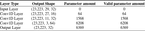
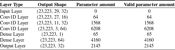
The CNN-Attention network model built in this study based on the feature extraction mechanism can automatically extract data features and enhance the learning of important features when performing the static gesture recognition task, as shown in Figure 26. The input data of the model’s input layer contains 5 flexible fiber optic sensor data and 24 JY901S quaternion data, and in the data encoding stage, each piece of input data is converted into a 2D matrix with 32-bit floating point numbers and a time step of 29. The model implicit layer includes CNN module and Attention module. Firstly, the 2D matrix is input to the Conv1D layer to complete the convolution and pooling operation to capture the data features, and the formula for the convolution operation is shown in Equation (8). Meanwhile, ReLU is used as the activation function in each Conv1D layer, and the ReLU activation function has the characteristics of zero-activation sparsity and suppression of gradient vanishing, For negative inputs, the activation value is set to zero, thus introducing sparsity, and its functional form is shown in Equation (9), and then different weight values are assigned through the attention mechanism layer to enhance the learning of key feature information, which enables the model to better learn the relevant information of the input data and make more accurate predictions. The model output layer completes the static gesture classification output by using full connectivity, while using the Softmax activation function, whose functional form is shown in Equation (10). The Softmax function has the characteristics of probability normalization, translation invariance and multi-category classification. By introducing exponential operation into the Softmax function, the output can be controlled between 0 and 1, which is used to map the output of the neural network into a probability distribution.
 \begin{equation} \text{output}=\text{Conv}1\text{D }\times \left(\text{input}\_ \text{shape}\times \text{filters}+\text{biasz}\right) \end{equation}
where
 $\text{output}$
is the output of the convolution operation,
 $\text{input}\_ \text{shape}$
is the input of the
 $\text{Conv}1\mathrm{D}$
layer,
 $\text{filters }$
is the number of convolution kernels in the
 $\text{Conv}1\mathrm{D}$
layer, and
 $\text{bias}$
is the bias value.
 \begin{equation} \begin{array}{c} \text{ReLU}\left(\mathrm{x}\right)=\begin{cases} \mathrm{x},\mathrm{x}\gt \mathrm{0}\\[5pt] \mathrm{0},\mathrm{x}\leq \mathrm{0} \end{cases} \end{array} \end{equation}
where
 $\mathrm{x}$
is the input to the neuron of the layer.
 \begin{equation} \begin{array}{c} \text{Softmax}\left(\mathrm{x}_{\mathrm{i}}\right)=\dfrac{\mathrm{e}^{{\mathrm{x}_{\mathrm{i}}}}}{\sum _{\mathrm{j}}\mathrm{e}^{{\mathrm{x}_{\mathrm{j}}}}} \end{array} \end{equation}
where
 $\mathrm{x}_{\mathrm{i}}$
and
 $\mathrm{x}_{\mathrm{j}}$
are the outputs of the neurons in the layer.
Parameter information of each layer in CNN network.

Parameter information of each layer in convolutional neural network-Attention network.

This system uses two different neural network models for static gesture recognition task, CNN network and CNN-Attention network, respectively. The structural information of these two networks is shown in Table II and Table III, respectively. In the gesture dataset, 70% of the data is used as a training set, and 30% of the data is used as a test set for training the model. After training, we get a model with an input size of 23,223. As shown in Table II and Table III, the number of trainable parameters of the CNN model is approximately the same as the number of parameters of the CNN-Attention model, but the single-step running time of the CNN network is 2 s, while the single-step running time of the CNN-Attention network model is 1s. The training process of this hybrid neural network is 200 iterations and 70% of the dataset is used as training set and 30% as test set. The model parameters can be assisted to achieve convergence by initializing the model parameters using truncated normal distribution, the mean is set to 0 and variance is set to 0.03. The learning rate is set to 0.001 and the batch size is set to 32. The loss function for classification task is selected as cross-entropy loss, and the functional formula of cross-entropy loss for multiclassification task is shown in Equation (11). The optimizer uses Adam, which is a gradient-based stochastic objective function first-order optimization algorithm, and the method outperforms the stochastic gradient descent algorithm and enables the model to converge faster.
 \begin{equation} \mathrm{L}=\dfrac{1}{\mathrm{N}}\sum _{\mathrm{i}}\mathrm{L}_{\mathrm{i}}=-\frac{1}{\mathrm{N}}\sum _{\mathrm{i}}\sum _{\mathrm{c}=1}^{\mathrm{M}}\mathrm{y}_{\mathrm{ic}}\log \left(\mathrm{p}_{\mathrm{ic}}\right) \end{equation}
where
 $\mathrm{M}$
is the number of categories,
 $\mathrm{M}$
is 33 in this task`;
 $\mathrm{y}_{\mathrm{ic}}$
is the sign function (0 or 1), if the real category of sample
 $\mathrm{i}$
is equal to
 $\mathrm{c}$
,
 $\mathrm{y}_{\mathrm{ic}}$
takes 1, otherwise it takes 0;
 $\mathrm{p}_{\mathrm{ic}}$
is the predicted probability of observing that sample
 $\mathrm{i}$
belongs to category
 $\mathrm{c}$
; and
 $\mathrm{N}$
is the size of the batch size.
After 200 iterations, the training accuracies of the CNN network and CNN-Attention network were 99.21% and 99.76%, respectively, as shown in Figure 27. The correct rates both converge with the increase of iterations, and the CNN network model enters a slow convergence stage at two-thirds of all iterations, while the CNN-Attention network enters a slow convergence stage at one-third of all iterations with a better fit. Under the consideration of model training time, number of model training parameters, and model training accuracy, CNN-Attention network can accomplish the static gesture recognition task.
Static gesture accuracy trends.

4.2. Dynamic gesture recognition method
The dynamic gesture data set of this study is a time series formed by multiple static gesture transitions. The input dynamic gesture data can be regarded as a continuous time series. In order to improve the accuracy of dynamic gesture recognition, a network that can process time series data and capture the time dependence of the data needs to be introduced in dynamic gesture recognition. RNN network has memory function, and RNN network better captures the time sequence information in the data. RNN and feedforward neural network (such as CNN, fully connected network) both contain input layer, hidden layer, and output layer in structure, but they have obvious differences in information transmission. The feedforward neural network transmits data along a fixed direction, and each node updates the input data through different weights, which is suitable for processing static data. In contrast, RNN introduces a loop mechanism at each node, and the output of the current node is affected by the previous node. Impact, so it can effectively capture the temporal dependencies in sequence data, is suitable for processing data with time dimensions, can better understand and utilize long-term dependencies in sequence data, and performs well when processing dynamic data. However, traditional RNN suffers from exponential growth or decay gradient problems when processing long-term sequences, and cannot effectively maintain or transmit long-term state information. To solve this problem, LSTM network and Bi-LSTM network, as variant structures of RNN, have better long-term dependency modeling capabilities and more stable model training performance by introducing gating mechanisms and memory units, which effectively solve the limitations of traditional RNN. Therefore, this research uses the LSTM network and its variants to complete the dynamic gesture recognition task.
LSTM control structure diagram.

Bidirectional long and short-term memory structure.

As shown in Figure 28, the LSTM network unit is realized by connecting forgetting gate, input gate, and output gate in series. The forgetting gate decides how much information is left behind by the previous neural unit features. The input gate takes the input data
 $\mathrm{x}_{\mathrm{t}}$
through the action of Sigmoid and tanh functions, combining them to update the feature information. The output gate’s role is to update the output to control how many features are filtered out of the current state.
where the formula is:
 \begin{align*} \begin{array}{llll}&\text{forgetting gate: } & f_{t} &= \sigma (W_{f} \cdot [h_{t-1},x-{t}]+b_{f})\\[5pt] &\text{input gate: } & i_{t} &= \sigma (W_{i} \cdot [h_{t-1},x-{t}]+b_{i})\\[5pt] &\text{output gate: } & o_{t} &= \sigma (W_{o} \cdot [h_{t-1},x-{t}]+b_{0})\\[5pt] &&&h_{t} = o_{t} \ast \textrm{tanh}(g_{t})\end{array} \end{align*}
where
 ${\unicode[Arial]{x03C3}}$
denotes the Sigmoid function;
 $\mathrm{W}_{\mathrm{f}}$
,
 $\mathrm{W}_{\mathrm{i}}$
, and
 $\mathrm{W}_{\mathrm{o}}$
denote the corresponding
 $\mathrm{x}_{\mathrm{t}}$
and
 $\mathrm{h}_{\mathrm{t}-1}$
multiplication matrix weights; and
 $\mathrm{b}_{\mathrm{f}}$
,
 $\mathrm{b}_{\mathrm{i}}$
, and
 $\mathrm{b}_{\mathrm{o}}$
denote the bias values of the corresponding gates.
Convolutional neural network-bidirectional long and short-term memory network model structure.

Trends in accuracy of dynamic gesture recognition networks.

In LSTM networks, states are transmitted from front to back in the time dimension. However, the output of the current moment is sometimes related not only to the previous state but also to the state afterward. Adding a chain of states transmitted in the reverse direction to the LSTM structure constitutes a Bi-LSTM, the structure of which is shown in Figure 29: Bi-LSTM can be regarded as a combination of two unidirectional LSTMs propagating states in opposite directions of transmission, where the inputs are provided to both LSTMs in opposite directions and the outputs are jointly determined by the two unidirectional LSTMs at every moment t. The structure of Bi-LSTM allows it to be used in a network that is not only an LSTM but also an LSTM with an LSTM in the opposite direction of state transmission, which is an LSTM in the opposite direction. Network structure of the LSTM makes it possible to access the temporal dependencies of the time series data in both forward and reverse directions in order to extract more comprehensive time dimension features and improve the accuracy of time series identification.
The data features extracted by the CNN network through convolution and pooling operations can provide more informative representations for subsequent networks, and the Bi-LSTM network can memorize important feature information in the past to future and future to past directions through a gating mechanism, which can further extract the features of the input sequence based on the CNN network, speed up the training speed of the model, and improve the performance of the model. Therefore, this study uses the CNN-Bi-LSTM network model to complete the dynamic gesture recognition task, and the network structure is shown in Figure 30. After the landmark gesture is recognized, the continuous static gesture results with a time step of 20 are input into the dynamic gesture recognition network. The input data of the input layer of the network model is the one-hot encoding of the static gesture output. In the data encoding stage, the one-hot encoding of the input static gesture is converted into binary, and the input data shape becomes a two-dimensional matrix of (20, 5). The hidden layer includes CNN module and Bi-LSTM module. First, the two-dimensional matrix of the data encoding stage is input into the CNN module for convolution and pooling operation, where the number of convolution kernels is 32, the convolution kernel size is 3, and the pooling kernel size is 2; then the data output by the Conv1D layer is input into the Bi-LSTM module, where the number of nodes in the first and second layers of the Bi-LSTM is 8. The Dropout structure is added after the Bi-LSTM layer, and the output of some neurons is set to 0 during training to reduce the overfitting of the model and enhance the generalization ability of the model. The model output layer completes the dynamic gesture classification output by using a fully connected layer.
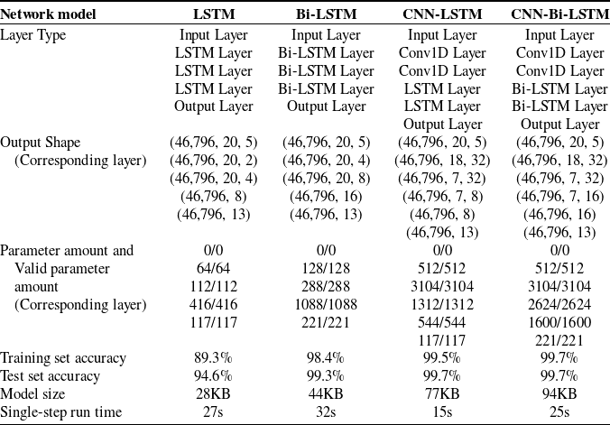
Use 70% of the gesture data set as the training set and 30% as the test set, respectively. Figure 31 (a), Figure 31 (b), Figure 31(c), and Figure 31 (d) show the trend curves of dynamic gesture accuracy and loss rate obtained by LSTM network, Bi-LSTM network, CNN-LSTM network, and CNN-Bi-LSTM network trained on PC, respectively. Table IV summarizes the model parameters and information of the gesture recognition network. From the comparative analysis of Figure 31 (a), Figure 31 (b), it can be seen that the recognition accuracy of LSTM network is only about 94%, and it starts to converge at 35 epochs; while after adding the bidirectional structure, the Bi-LSTM network is significantly better than the LSTM network in terms of the recognition accuracy and convergence, with an accuracy of more than 99%, and it starts to converge at 25 epochs. From the comparative analysis of Figure 31 (a) and Figure 31 (c) and Figure 31 (b) and Figure 31 (d), it can be seen that after adding CNN for feature extraction, the recognition effect of both LSTM network and Bi-LSTM network is significantly improved, and the recognition accuracy is more than 99%, and starting to converge at 15 epochs; from the comparative analysis, it can be seen that the accuracy of CNN-Bi-LSTM network overlaps between the test set and the training set at 25 epochs, while the accuracy of CNN-Bi-LSTM network overlaps between the test set and the training set at 10 epochs, which indicates that the CNN-Bi-LSTM network fits the effect number in dynamic gesture training and does not show overfitting phenomenon.
Model parameters and information of gesture recognition networks.

As can be seen from Table IV, the data shape of the first dimension is 46,796. The number of training parameters of the Bi-LSTM network is 1725, which is more than twice that of the LSTM network, which is based on the fact that the Bi-LSTM network uses a bidirectional structure, which leads to a larger amount of model parameters. The single-step running time for the LSTM network is 27 s, and the single-step running time for the Bi-LSTM network is 32 s. After adding the CNN network structure, although the network training parameters become larger, the single-step running time of the model is greatly shortened, with the single-step running time of 15s for the CNN-LSTM network, and the single-step running time of 25 s for the CNN-Bi-LSTM network, due to the fact that the CNN was used to preprocess the feature variables prior to performing the time series extraction preprocessing. In addition, Table IV shows that the gap between the training set and the accuracy set of the LSTM network is large, and the model is not easy to reach the saturation state, and the accuracy is low; the Bi-LSTM network has a higher accuracy, but it has the largest single-step running time of the model; from the parameters of the CNN-LSTM network and the CNN-Bi-LSTM network, it can be seen that, after the addition of the CNN, the accuracy rate of the model is improved, reaching more than 99%. Improved to more than 99%, and the single-step running time of the model has been reduced. From the Table IV, it can be seen that the size of the four network models are all within 100 KB, which is suitable for deploying any of the models in resource-constrained STM32 microprocessor chips for real-time human-computer interaction and gesture recognition. In summary, from Figure 31 and Table IV, it can be concluded that CNN-Bi-LSTM is suitable for use in dynamic gesture recognition tasks due to its high recognition accuracy, good fitting, shorter single-step runtime, and smaller model size.
5. Experimental validation and analysis of experimental results
After completing the training of the gesture dataset, the deployment of the gesture recognition model needs to be completed and validated and analyzed in the built simulation platform.
5.1. Gesture recognition algorithm porting
Traditional wearable gloves are only responsible for the data collection of hand gestures and sending the collected data to the PC side before data processing, so the gesture recognition network model only needs to run on the PC side, but in order to realize gesture recognition on the data glove side in this system, it is necessary to run the gesture recognition network model on the STM32 microprocessor. X-CUBE-AI is A plug-in from STMicroelectronics to quickly and easily convert the AI framework for neural networks into C code in embedded systems, which in turn can be integrated into keil5 project engineering to implement AI functionality to run on STM32 processors with limited RAM resources.
This system uses the Keras framework to complete the gesture recognition network transplantation. Since the trained gesture recognition network needs to be deployed into the STM32 microprocessor, the network model should not be too large, so this system uses the CNN-Attention network to complete the static gesture recognition task, and the CNN-Bi-LSTM network to complete the dynamic gesture recognition task. When the model is deployed, it is compressed by X-Cube-AI, and the complexity of the model derived by X-CUBE-AI is evaluated by using the MACC (Multiply-Accumulate Operations) parameter, which is converted into the size of the memory occupied in the microprocessor Flash, which is then computed by the Formula (12). The running time of the model is calculated using Equation (12). Nine clock cycles per complexity MACC operation is known from the official documentation of the microprocessor
 \begin{equation} \text{time }=9\times \text{ MACC }\times \frac{1}{\text{freq}} \end{equation}
where
 $\text{freq}$
is the external clock frequency of the microprocessor of the system, and the value is 8 Mhz.
The model analysis is converted in STM32CubeMX, and the results are shown in Figure 32. According to the analysis results, it can be learned that the CNN-Attention network model occupies a Flash size of 68.47 KB, of which the weighting parameters occupy 55.63 KB, the related libraries occupy 12.84 KB, the total runtime RAM is 2.81 KB, and the value of MACC is 14,928. Therefore, the running time of the model is 16.794 ms. The CNN-Bi-LSTM network model occupies a Flash size of 54.09 KB, of which the weight parameters occupy 25.43 KB, the related libraries occupy 28.67 KB, and the total running RAM is 5.11 KB. The MACC value of the model is 50, 480, and therefore the model’s running time is 56.79 ms. To summarize, this study proposes a dual-network gesture recognition method based on the Keras framework is suitable for running in resource-constrained STM32 microprocessors.
Static and dynamic network analysis results.

5.2. Simulation system validation analysis
Hardware-in-the-loop (HIL) simulation is one of the important ways to design simulations based on models. HIL simulation adds the UAV hardware controller to the UAV software simulation system, close to the actual flight of the UAV. Hardware analog simulation using the principle of similarity firstly adds the UAV flight controller to the simulation system of the UAV. Secondly the UAV control algorithms executed on the actual controller are fed back to the main UAV model part and, finally, executed on the virtual simulation system computer.
For the requirements of HIL simulation design, a UAV training scenario based on AirSim and Virtual Engine 4 platform is constructed to simulate the HIL of the UAV, and the simulation architecture is mainly divided into two parts: hardware and software. The hardware part is the controller part, which consists of the data glove and the flight controller Pixhawk, and functions as the connection point between the simulation platform and the actual UAV. The software part consists of the UAV module, the sensor module, the environment module, the physical navigation system module, and the API layer.
After completing the AirSim UAV hardware and software testing, a hardware loop simulation of the UAV was conducted in this study in order to test the accuracy of the flight simulation system platform. The performance of the UAV HIL simulation system was evaluated through the collection of position and pose data and data analysis of the UAV model in flight.
The simulation test environment is shown in Figure 33. The left side shows the UAV simulation scene in AirSim. The right side is the GS interface, in which the left side of the upper border shows that the UAV is in the unlocked or locked state, the right side shows the flight mode of the UAV at this time, the red arrow in the center indicates the virtual position of the UAV at this time, the two circular interfaces in the upper-right corner are the gyroscope showing the inclination angle of the UAV’s flight, and the geomagnetometer showing the nose orientation, and the square interface below shows the altitude of the UAV, the UAV’s speed to the ground, the take-off time and other flight data. At the bottom is the UAV’s attitude angle, including pitch angle, roll angle, and yaw angle, displayed from the GS’s MAVLink console interface.
Unmanned aerial vehicle simulation environment.

Firstly, the data glove makes a gesture for UAV gesture recognition, and then maps the gesture recognition result with the MAVLink control commands and sends them. As the MAVLink protocol has certain requirements for the sending frequency of various commands, we use a timer within the glove chip for accurate timing to send, the heartbeat packet sending frequency is set to 2 Hz, and the control command sending frequency is set to 25 Hz. Commonly used specific static and dynamic gesture commands are mapped and simulated with the control effect as shown in Figure 34 and Figure 35. The HIL simulation results show that the data glove is reliable in the real environment, that is, under the interference of certain environmental factors, the static gesture control, and the continuous combination of static gestures into dynamic gesture control drone flight are reliable.
Glove static control unmanned aerial vehicle simulation.

Glove dynamic control unmanned aerial vehicle simulation.

5.3. Real scenario validation analysis
Different experimental scenarios were constructed by using 20 stretchable rods placed in the school playground to verify the performance of the system’s data glove for UAV control. In this experiment, the TELEM1 port of the Pixhawk6c flight controller is used to receive the MAVLink commands sent by the wearable device to control the flight of the UAV; and the TELEM2 port is used to connect to the GS to send the flight trajectory of the UAV to the GS for real-time display.
The validation scheme of this experiment is to put the data glove device on the hand and control the UAV to fly along the designed experimental scenarios. There are three experimental scenarios in this experiment, which are "P" type experimental scenario, "M" type experimental scenario, and "8" type experimental scenario. The actual flight scenarios and the flight path of the GS are shown in Figure 36, and the results of the flight experiments are shown in Table V. The "P" type experimental scenario is used to test the UAV’s straight-line flight when the nose direction is unchanged; the "M" type experimental scenario is used to test the UAV’s straight-line flight when the nose direction is changed; and the "8" type experimental scenario is used to test the UAV’s straight-line flight when the nose direction is changed. Combining the flight trajectory of the GS in Figure 36 and the test results in Table V, it can be seen that the UAV had a smooth overall flight trajectory during flight, a clear right-angle trajectory, and no collision phenomenon. There are only two control failures in the "8" scenario, both occurring in the hold mode and fixed-point mode switching, which can make the UAV fly stably, and the control failure in the "8" scenario is not obvious. Both modes can make the UAV fly stably and have no effect on the experiment, which proves that the data glove device is stable and safe for the flight control of the UAV. In summary, the system can accomplish stable control of UAVs in complex environments.
Experiments on real scenarios with drones.

6. Conclusions and future work
In this study, a data glove based on multi-sensor fusion is designed, which integrates the core functions of gesture data processing, gesture recognition, and UAV command sending on STM32 embedded chip. Based on the Attention-CNN network and CNN-Bi-LSTM network deployed on the low-power embedded device, static gestures and dynamic gestures are recognized, respectively, in which the average recognition accuracy of 32 static gestures reaches 99.7%, and the average recognition accuracy of 13 dynamic gestures reaches 99.9%. Experimental tests conducted on the AirSim-based simulation platform and in real scenarios show that the gesture recognition method is able to perform continuous gesture recognition on low-power and low-cost embedded devices, and can be converted into control commands for real-time and stable flight control of UAVs. It effectively solves the problem of complex operation and high learning cost of traditional drone control systems, and lowers the threshold for users. Operators do not need to master in-depth professional control skills, but only need to learn specific drone operation gestures to effectively complete the flight control of the drone.
Unmanned aerial vehicle real-scene test.

This study provides a foundation for future research directions. Research experiments have shown that multi-sensory fusion gesture-controlled drones are a reliable and efficient way of interaction, and can fly multiple paths according to gesture instructions. Looking to the future, gesture-controlled drones based on multi-sensor fusion are expected to play a greater role in complex industrial scenarios and high-risk environments, such as remotely controlling drones to perform tasks such as material transportation and assisting in rescue operations. This technology not only improves operational flexibility and safety but also significantly reduces the risk of manual intervention. In addition, by installing advanced sensors such as infrared cameras and lidar on drones, the drone’s ability to explore in unknown environments can be improved. The drone collects data for real-time perception and analysis of complex environments, and generates three-dimensional maps, providing technical support for drones in exploring unknown areas. In the future, we can continue to develop in the fields of drone artificial rescue and drone artificial exploration, and gesture control of drones will become an important tool in the field of human-computer interaction.
Author contributions
Guang Liu, Yang Liu, and Shurui Fan conceived and designed the paper. Guang Liu, Yang Liu, Weijia Cui, and Kewen Xia conducted paper gathering. Guang Liu, Yang Liu, and Li Wang wrote the paper.
Financial support
The research was supported by the National Natural Science Foundation of China (No. 42075129), Key Research and Development Project from Hebei Province of China (No. 19210404D, No. 21351803D), Supported by Science and Technology Cooperation Special Project of Shijiazhuang (SJZZXB23004).
Competing interests
We declare that we have no known competing financial interests or personal relationships that could have appeared to influence the work reported in this paper.
Ethical approval
None.