1 Introduction
In engineering applications, fluid–structure interactions (FSIs) are common but complex to understand. In low Reynolds number vehicles, flow induced forces and moments can result in negative effects for maintaining operation stability while operating along a predetermined path under remote control.
Vortex-induced vibrations (VIVs) of an elastically mounted square cylinder have been studied experimentally and numerically at low and high Reynolds numbers. As reviewed by Griffin (Reference Griffin1985), Sarpkaya (Reference Sarpkaya2004) and Williamson & Govardhan (Reference Williamson and Govardhan2004), the characteristic vibration frequencies are classified into three different regions called the ‘lock-in’, ‘lock-on’ and ‘synchronization’ regions when an elastically mounted cylinder is oscillated in a transverse direction with large amplitudes. Obasaju, Ermshaus & Naudascher (Reference Obasaju, Ermshaus and Naudascher1990) undertook experiments to investigate the streamwise vibrations of an elastically mounted square cylinder and the associated vortex dynamics at
 $3.2\times 10^{3}<Re<1.4\times 10^{4}$
and
 $0<\unicode[STIX]{x1D6FC}<45$
with
 $3<U_{red}<13$
(where
 $Re$
is the Reynolds number,
 $\unicode[STIX]{x1D6FC}$
is the angle of incidence and
 $U_{red}$
is the reduced speed), systematically. Minewitsch, Franke & Rodi (Reference Minewitsch, Franke and Rodi1994) performed numerical simulations for a square cylinder oscillating only in the streamwise direction at
 $Re=200$
to study the resulting vortex shedding in the wake region. Taylor & Vezza (Reference Taylor and Vezza1999) numerically investigated the forced transverse oscillations of a square cylinder at
 $Re=20\,000$
. Cheng, Zhou & Zhang (Reference Cheng, Zhou and Zhang2003) experimentally studied the flow-induced vibration control in a square cylinder at
 $Re=3500$
using piezoelectric ceramic actuators. Amandolese & Hemon (Reference Amandolese and Hemon2010) experimentally studied the transverse vibrations of an elastically mounted square cylinder at
 $2000<Re<8000$
in the reduced velocity range,
 $5<U_{red}<20$
and showed initial and lower branches within the limit cycle oscillation in the plots of the reduced frequency versus the reduced velocity. The vortex shedding modes coupled with the characteristic vibration dynamics were characterized with the number of vortices and their pattern by Williamson & Roshko (Reference Williamson and Roshko1988), as below:
-
(i) 2S mode: positive and negative vortices are shed per cycle, alternately;
-
(ii) 2P mode: two pairs of vortices (a pair of vortices comprising a positive and a negative one) are shed per cycle;
-
(iii) P
 $+$
S mode: mixture of 2S and 2P modes in a half-cycle.

In fact, the cross-sections of most micro aerial vehicles (MAVs) are not circular but non-axisymmetric with corners. A net pressure force induced by vortex shedding can result in translational vibrations. However, while pressure force vectors on the surface of an ideally circular structure are toward its barycentre, those on an angular structure are not exactly aligned and therefore non-zero moments can be exerted on that of an angular object. Hence, it is fair to say that most freely rotatable vehicles are exposed to the pressure-force-induced moment. In spite of such a physical relevance, vortex-induced rotations (VIRs) have been rarely studied as compared with VIVs. Tatsuno et al. (Reference Tatsuno, Takayama, Amamoto and Ishi-i1990) experimentally studied a freely rotatable square cylinder in a uniform flow at
 $Re=3.5\times 10^{4}$
. Zaki, Sen & Gad-El-Hak (Reference Zaki, Sen and Gad-El-Hak1994) recognized four distinct responses of a freely rotatable square cylinder to vortex shedding frequencies in a range of Reynolds numbers from 1000 to 10 000: (i) a rest stable position, (ii) oscillation, (iii) reverse rotation and (iv) autorotation. Recently, Park, Min & Ha (Reference Park, Min and Ha2015) numerically performed parametric investigations of VIR of a freely rotatable square cylinder with respect to three Reynolds numbers (
 $Re=50,100,150$
) and five aspect ratios. Although they mapped the characteristic rotation responses (oscillation and autorotation) with respect to the two variables with a fixed moment of inertia, rotation responses for other Reynolds numbers have not been characterized. Moreover, moment generating mechanisms, relevant rotation dynamics and flow patterns are not well understood. Hence, the objective of this paper is to characterize the rotation response of the cylinder to a uniform cross-flow and to investigate the associated moment generating mechanisms in a range of low Reynolds numbers
 $45\leqslant Re\leqslant 150$
. It should be noticed that VIRs of a rigid square cylinder also depend on the moment of inertia. However, our objective is targeted at studying only Reynolds number effects on VIRs.
The so-called ‘autorotation’ is the regime that has received the most attention; here, autorotation is defined as continuous rotation of a freely rotatable object in an azimuthal direction in a uniform cross-free-stream flow. Lugt (Reference Lugt1983) reviewed this distinct phenomenon. Maxwell (Reference Maxwell1854) investigated the autorotation of a freely falling card. Riabouchinsky (Reference Riabouchinsky1935) studied the autorotation behaviour of a four-bladed rotor. Smith (Reference Smith1971) experimentally identified three characteristic regions of a freely falling wing in a range of Reynolds number and moment of inertia: (i) stable motion, (ii) rocking motion and (iii) autorotation. Iversen (Reference Iversen1979) studied the correlation of autorotation characteristics of a flat plate with respect to Reynolds number, moment of inertia and wing configuration experimentally. Lugt (Reference Lugt1980) studied the reason for autorotation by means of numerical solutions of the Navier–Stokes equations in a flat plate and elliptical cylinder and established that autorotation occurred due to the synchronization between vortex shedding and the rate of rotation. Skews (Reference Skews1991) experimentally investigated the autorotations of cylinders (which have polygonal cross-sections) and found that an angular cylinder can autorotate only if the cylinder has less than eight edges. Recently, Greenwell & Garcia (Reference Greenwell and Garcia2014) reported two aspects of the autorotation dynamics of a rectangular prism by means of experiments: the ‘lock-in’ region and static hysteresis in the autorotation rate. Further, Greenwell (Reference Greenwell2014) investigated aspect ratio effects on the autorotation dynamics of the prism. In this paper we investigate the inception of the autorotation regime and study the detailed vortex shedding dynamics occurring during the transition between stable oscillatory rotation and autorotation.
This paper is structured as follows. In § 2 the governing equations for a flow and rotatable, rigid object are given. In addition, a description of the numerical method is included together with details about the computational domain and boundary conditions in the section. In § 3 two-dimensional FSI simulation results are detailed and discussed. Finally, the findings are summarized in § 4.
2 Governing equations, numerical method and computational domain
2.1 Governing equations
We consider the two-dimensional fluid problem of a freely rotatable, rigid square cylinder in a uniform cross-flow. The governing equations for the fluid flow are the time-dependent three-dimensional Navier–Stokes equations for an incompressible fluid. The set of equations for mass and momentum conservation of the fluid are as follows:
 $$\begin{eqnarray}\displaystyle & \displaystyle \frac{\unicode[STIX]{x2202}u_{k}}{\unicode[STIX]{x2202}x_{k}}=q, & \displaystyle\end{eqnarray}$$
 $$\begin{eqnarray}\displaystyle & \displaystyle \frac{\unicode[STIX]{x2202}u_{i}}{\unicode[STIX]{x2202}t}+u_{k}\frac{\unicode[STIX]{x2202}u_{i}}{\unicode[STIX]{x2202}x_{k}}=-\frac{\unicode[STIX]{x2202}p}{\unicode[STIX]{x2202}x_{i}}+\frac{1}{Re}\frac{\unicode[STIX]{x2202}^{2}u_{i}}{\unicode[STIX]{x2202}x_{k}\unicode[STIX]{x2202}x_{k}}+f, & \displaystyle\end{eqnarray}$$
where
 $u_{i}$
is the velocity vector;
 $x_{i}$
are the spatial coordinates;
 $q$
is the mass source/sink;
 $t$
is the time;
 $\unicode[STIX]{x1D70C}$
is the density of fluid;
 $p$
is the pressure; and
 $Re$
is the Reynolds number based on the side of the square cylinder
 $h$
, the approach flow velocity
 $U$
and the kinematic viscosity of the fluid
 $\unicode[STIX]{x1D708}$
(
 $Re=Uh/\unicode[STIX]{x1D708}$
);
 $f$
is the moment forcing; all the physical variables are non-dimensionalized by the free-stream velocity
 $U$
and the side length
 $h$
of the square cylinder.
The problem is governed by Newton’s second law of motion and the governing equation for a rigid body free to rotate only in the azimuthal direction (i.e. one degree of freedom), is as follows:
 $$\begin{eqnarray}I\frac{\text{d}^{2}\unicode[STIX]{x1D703}}{\text{d}t^{2}}=\unicode[STIX]{x1D70F},\end{eqnarray}$$
where
 $I$
is the mass moment of inertia,
 $\unicode[STIX]{x1D703}$
is the rotation angle and
 $\unicode[STIX]{x1D70F}$
is the torque defined as the tangential force
 $f_{t}$
times a moment arm
 $R$
. A fixed reduced mass of the square cylinder
 $M_{red}=2$
(defined as
 $m/\unicode[STIX]{x1D70C}h^{2}$
where
 $m$
is the mass of the cylinder) is used for two-dimensional FSI simulations.
Schematic of (a) computational domain and (b) Eulerian grid in full size.

2.2 Computational domain, grid and boundary conditions
The integration domain and its size are described in figure 1(a). Two kinds of grid, a Eulerian grid for the flow variable integration and a Lagrangian grid for the rigid body rotation of a square cylinder, are used for our FSI simulations. As shown in figure 1(b), the background integration domain is discretized with
 $760\times 602$
nodes and the Eulerian grid is locally fine near the initial position of the square cylinder and the wake region. The Lagrangian grid is composed of 952 triangle faces which are uniform in size. The grid resolution is determined by the grid refinement study to ensure a low sensitivity of our obtained solutions to the grid resolution. The computational domain is initialized by the free-stream flow velocity (
 $u=U$
,
 $v=0$
) and the square cylinder is initially in a rest position with zero rotation angle so that the initial conditions are symmetric in the integration domain. No explicit asymmetric disturbances are introduced to induce rotational motion of the square cylinder for initial transient states, i.e. small floating point representation errors eventually grow. At the inlet of the computational domain a constant inflow condition (
 $u=U$
,
 $v=0$
) is imposed. A free-slip boundary condition (
 $\unicode[STIX]{x2202}u/\unicode[STIX]{x2202}y$
,
 $\unicode[STIX]{x2202}v/\unicode[STIX]{x2202}y=0$
) is employed at the top and bottom boundaries. A convective boundary condition is imposed on the outlet.
2.3 Numerical method
Numerical solutions to the incompressible Navier–Stokes equations are time integrated by hybrid low-storage third-order Runge–Kutta time stepping. The spatial discretization is constructed with the central second-order accurate finite-difference scheme on a Cartesian staggered mesh. Further details of the numerical method are described in Verzicco & Orlandi (Reference Verzicco and Orlandi1996). The equation of motion (3.2) is integrated by the fourth-order Hamming predictor–corrector implicit approach. The moving boundary of an object and embedded boundary conditions are reconstructed every time step by using the moving-least-squares (MLS) immersed boundary method (IBM) (Vanella & Balaras Reference Vanella and Balaras2009).
Time history of transverse oscillation amplitude (
 $y/D$
) of two one degree of freedom (1-DOF) cylinders in tandem for different reduced velocities. (a)
 $U_{red}=4$
; (b)
 $U_{red}=8$
.

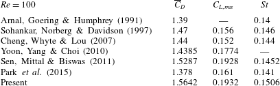
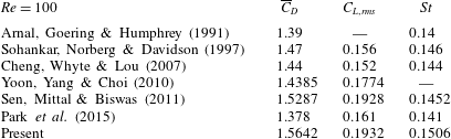
Comparison of mean drag coefficient (
 $\overline{C}_{D}$
), lift coefficient fluctuations (
 $C_{L,rms}$
) and the Strouhal number (
 $St$
) with reference results.
2.4 Code validation
The fluid–structure interaction problems studied in this paper are solved using an immersed-boundary Navier–Stokes solver coupled with a simple one degree of freedom structural solver. Only two modes of structural motion are considered: rotation and translation. In this section, we analyse and assess the accuracy of the fluid solver in the absence of structural motion, and fluid–structure interactions for problems involving translations of the solid. In the remaining of the paper we will focus on fluid–structure interactions involving rotation.
First, we numerically solve flows around a fixed, rigid square cylinder for
 $Re=100$
to assess the accuracy of the flow solver. The calculated mean drag coefficient, root-mean-square lift coefficient and Strouhal number are compared with reference results in table 1 and our result shows satisfactory quantitative agreement.
In the next step, we validate the coupled flow and structure solvers focusing on interactions between translational motions of rigid objects and flows. Adopting the benchmark case of Borazjani & Sotiropoulos (Reference Borazjani and Sotiropoulos2009), we investigate vortex-induced oscillations of two identical, circular cylinders in tandem at
 $Re=200$
. The system has only transverse vibrations, i.e. 1-DOF. Figure 2 displays the time history of vibration amplitudes of the front and rear cylinders with respect to
 $U_{red}=4$
, 8 (defined as
 $U_{red}=U/fD$
where
 $f$
is the natural frequency of the cylinder and
 $D$
is the diameter of the cylinder) at
 $M_{red}=2$
(defined as
 $M_{red}=m/\unicode[STIX]{x1D70C}D^{2}$
). For
 $U_{red}=4$
the dynamic responses of front and rear cylinders are comparable during the early transient time but beyond a certain time the oscillation amplitude of the front cylinder is larger. This trend is in good agreement with Borazjani & Sotiropoulos (Reference Borazjani and Sotiropoulos2009) (see their figure 6b) but in our simulation results the time to attain the statistically stable state is approximately two times longer than their result. For
 $U_{red}=8$
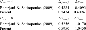
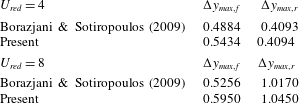
the reported transition between the amplitudes of the front and rear cylinders (see figure 6d in Borazjani & Sotiropoulos Reference Borazjani and Sotiropoulos2009) is qualitatively well predicted in our simulation results, as shown in figure 2(b). Moreover, the maximum amplitudes of the front and rear cylinders in cases
 $U_{red}=4$
and 8 are in quantitative agreement with the reference results, as displayed in table 2. Dynamic relations between lift force coefficient and oscillation amplitude are also assessed. Figure 3 shows the phase portraits of the two physical variables at the reduced velocities. The transverse force coefficients and oscillation amplitudes at
 $U_{red}=4$
and 8 are in- and out-of-phase, respectively, and they are consistent with those of Borazjani & Sotiropoulos (Reference Borazjani and Sotiropoulos2009) (see their figure 8b,f).
Phase portrait of displacement relative to lift coefficient at two different values of
 $U_{red}$
for the 1-DOF tandem system. (a)
 $U_{red}=4$
; (b)
 $U_{red}=8$
.

Comparisons of maximum vibration amplitudes (
 $\unicode[STIX]{x0394}y_{max}$
) with the results of Borazjani & Sotiropoulos (Reference Borazjani and Sotiropoulos2009) at
 $U_{red}=4$
and 8. The subscripts
 $f$
and
 $r$
refer to the front and rear cylinders, respectively.
In the next sections we will focus on flow-induced rotations, however as an additional validation case we mention the results of de Tullio, Pascazio & Napolitano (Reference de Tullio, Pascazio and Napolitano2012). They validated the present code by numerically solving a flow past an elliptic particle sedimenting in a channel and compared their calculated cross-wise and angular positions with experimental results. Their study is helpful to establish the accuracy of the code in prediction of interactions between angular motions of an object and flows.
Time history of rotation angle
 $\unicode[STIX]{x1D703}$
(
 $\unicode[STIX]{x1D703}$
is accumulated in clockwise direction) of a freely rotating square cylinder for twelve different Reynolds numbers.

3 Results
3.1 Characteristic rotation behaviours
As represented in figure 4, the dynamic response of a square cylinder to a two-dimensional (2-D) uniform cross-flow depends on the Reynolds number at
 $45\leqslant Re\leqslant 150$
and shows, globally, four characteristic regimes: a rest position, time-periodic rotational oscillation, random rotation and autorotation. Considering the different ranges of Reynolds number, the four characteristic regimes are qualitatively consistent with those reported by Zaki et al. (Reference Zaki, Sen and Gad-El-Hak1994) (
 $1000\leqslant Re\leqslant 10\,000$
). It is not surprising that the four regimes are recognized in the two different ranges of Reynolds number because the rotational motion also depends on the moment of inertia (as shown in (2.3)). It is notable that our simulation results exhibit two different time-periodic oscillations with asymptotic limits
 $\unicode[STIX]{x03C0}/2$
and
 $\unicode[STIX]{x03C0}$
. Moreover, it is also distinguishable that random rotations are observed between the two different oscillation regimes.
As displayed in figure 4(a), the square cylinder keeps an initial position at
 $Re=45$
because no vortex shedding occurs and the rotational response of the cylinder is not initiated (relevant flow patterns and moment generating mechanisms will be dealt with in § 3.2.1). Considering steady and symmetric vortex patterns emerge past a fixed square cylinder at
 $Re<50$
(Zaki et al.
Reference Zaki, Sen and Gad-El-Hak1994; Sen et al.
Reference Sen, Mittal and Biswas2011), a stable rest position at
 $Re=45$
is expected.
Maximum amount of rotation (
 $\unicode[STIX]{x0394}\unicode[STIX]{x1D703}_{max}$
) in an azimuthal direction with respect to Reynolds numbers (except for
 $Re=100$
, 110). Dashed lines denote asymptotic limits of
 $\unicode[STIX]{x0394}\unicode[STIX]{x1D703}_{max}$
(
 $\unicode[STIX]{x03C0}/2$
,
 $\unicode[STIX]{x03C0}$
,
 $2\unicode[STIX]{x03C0}$
).

At
 $50\leqslant Re\leqslant 70$
, the rotation responses show monoharmonic oscillations with small amplitudes around
 $\unicode[STIX]{x1D703}=0^{\circ }$
, as shown in figure 4(a). However, the rotation response in the three conditions considered indicate a delay in reaching their dynamic equilibrium states which increases with the Reynolds number. More precisely, it is found that increasing the Reynolds number in this regime leads to an increase in the time required for a rotation response to attain its dynamic equilibrium state. In addition, the maximum amount of rotation monotonically increases up to
 $Re=70$
, as shown in figure 5. We shall refer to this regime as ‘small-amplitude oscillation’, hereinafter.
At
 $Re=80$
and 90, the cylinder oscillates in the azimuthal direction with an elevated amplitude and it is confined within
 $\pm 1/4\unicode[STIX]{x03C0}$
. Whereas rotation responses at
 $50\leqslant Re\leqslant 70$
are monoharmonic, multi-frequency components are seen in this regime (as displayed in figure 4
b). Specifically, a bi-harmonic oscillation is found at
 $Re=80$
and multi-harmonic oscillation is pronounced at
 $Re=90$
. The generation mechanisms of the rotational instability emerging in this regime will be discussed in § 3.2.3. We refer to this regime as ‘
 $\unicode[STIX]{x03C0}/2$
-limit oscillation’.
At
 $Re=100$
and 110, our simulations exhibit intermittent oscillations and rotations in a temporally random fashion. Zaki et al. (Reference Zaki, Sen and Gad-El-Hak1994) also found such rotational behaviour at
 $4100<Re<4700$
, experimentally. It is notable that random rotation occurs in both the laminar and turbulent flow regimes. We refer to this regime as ‘random rotation’.
At
 $Re=120$
and 130, the rotation response of the cylinder recovers time-periodic oscillation from the random rotations but it has two different characteristics from that of previous regimes. First, the rotation response oscillates within a larger rotation limit
 $\unicode[STIX]{x03C0}$
. Second, while the curves in the ‘small-amplitude’ and ‘
 $\unicode[STIX]{x03C0}/2$
-limit oscillation’ regimes are sinusoidal, here they have a bell-like shape. We refer to this regime as ‘
 $\unicode[STIX]{x03C0}$
-limit oscillation’.
At
 $Re=140$
and 150, the cylinder autorotates in the clockwise direction. Park et al. (Reference Park, Min and Ha2015) also reported autorotation at
 $Re=150$
but without describing the physical properties (mass or moment of inertia), and therefore only qualitative comparisons are possible. Because the dynamic response of the cylinder does not transition directly from oscillatory to autorotation but undergoes a transient state at
 $t<100$
where random rotations are observed, the direction of autorotation could depend on the path from the transient state to the dynamic equilibrium one. In our simulation results, only clockwise autorotations are observed, as shown in figure 4(e).
3.2 Moment generating mechanisms
In this section, the moment generating mechanisms for the characteristic regimes (represented in § 3.1) are elucidated by investigating the flow structures around the square cylinder and the associated pressure distributions.
(a) Contours of instantaneous vorticity and (b) profile of pressure coefficient
 $C_{p}$
along the surface of the square cylinder for
 $Re=45$
.

3.2.1 Stable position (
$Re=45$
)

As mentioned in § 3.1, the square cylinder keeps the initial rest position with a symmetric flow pattern around the cylinder. Figure 6 confirms the symmetric pattern with no vortex shedding. Net pressure force vectors on the windward and leeward surfaces are toward the barycentre of the cylinder and those on the upper and lower surfaces are symmetrically located. Hence, VIR is not initiated at
 $Re=45$
due to the absence of a pressure-induced moment. The kept initial cylinder position confirms that small numerical oscillations induced by the immersed boundary method do not significantly influence the rotation response.
Contours of instantaneous spanwise vorticity with streamlines for
 $Re=60$
at (a)
 $t=300.5$
and (b) 304 when the amplitudes of the rotation angle
 $\unicode[STIX]{x1D703}$
are maximum and minimum in a period, respectively. Arrows depict deviations of net pressure force vectors on the four sides of the cylinder. Blue and red colours of arrows denote that the corresponding net pressure force vector generates clockwise and counter-clockwise moments, respectively.

3.2.2 Small-amplitude oscillation (
$Re=60$
)

Driving moments for small-amplitude oscillations (represented in § 3.1) are resulting from the emergence of vortex shedding. As displayed in figure 7(a), at a time instant A (when
 $\unicode[STIX]{x1D703}$
is maximum in a period), the flow passing over the upper side separates at the right upper corner and reattaches on the lower part of the leeward surface. The recirculation bubble (where the pressure is locally low) is hence located near the upper part of the wake region. This asymmetric location of the bubble results in the deviation of the associated net pressure force vector from the centreline on the leeward surface. Moreover, the maximum rotation in the clockwise direction leads to asymmetric pressure distributions on the resultant pressure and suction sides. The asymmetric net pressure force vectors on the three sides generate clockwise moments, as described by the blue arrows in figure 7(a). On the other hand, the stagnation pressure pocket on the windward surface is located diagonally with the location of the recirculation bubble as a result of the small clockwise rotation of the cylinder. The resulting asymmetric location of the stagnation pressure pocket on the windward surface hence generates a counter-clockwise moment, as shown in figure 7(a).
In B, as the cylinder rotates in the counter-clockwise direction and the angle of rotation reaches its minimum, the recirculation bubble is now located in the lower part of the wake region (as displayed in figure 7 b). This opposite location of the recirculation bubble with that in A determines a moment of opposite sign. In spite of the time-periodic oscillations, instantaneous flow patterns seen in figure 7 are still in the ‘main separation’ regime of the map where flow patterns of a fixed square cylinder are characterized with respect to the Reynolds number and the angle of incidence by Yoon et al. (Reference Yoon, Yang and Choi2010) (see their figure 4). In other words, a regular von Kármán vortex street observed in the fixed cylinder case is not significantly distorted by VIR in this regime due to the small amplitude of rotation.
The depicted recirculation zone in the wake region changes its location in an alternating manner and accordingly, the relevant pressure distribution along the surface of the cylinder also varies in the same manner. The resulting total net moment remains out-of-phase with the angle of rotation. Driven by the out-of-phase moment, the dynamic response of the cylinder is suppressed at the maximum or minimum angle of rotation. As a result, the cylinder maintains time-periodic oscillations with a small level of amplitude without further amplifications (as shown in § 3.1).
Time history of rotation angle
 $\unicode[STIX]{x1D703}$
, non-dimensionalized angular velocity
 $\unicode[STIX]{x1D714}h/U$
and moment coefficient
 $C_{m}$
(defined as
 $2M/\unicode[STIX]{x1D70C}U^{2}Ah$
where
 $A$
is the cross-section area of cylinder) in a time interval for
 $Re=80$
.

3.2.3
$\unicode[STIX]{x03C0}/2$
-limit oscillation (
$Re=80$
)


In this section, the moment generating mechanism for the ‘
 $\unicode[STIX]{x03C0}/2$
-limit oscillation’ regime is investigated. As mentioned in § 3.1, there are two distinct characteristics in this: (i) the steep rise of magnitude of the rotation angle and (ii) the interference of multi-frequency component(s) to the fundamental sinusoidal oscillation. To elucidate these characteristics, we analyse the flow in five time instants in a period of the fundamental oscillation for
 $Re=80$
.
First, the rotation dynamics for
 $Re=80$
is explained in a period of fundamental oscillation. Figure 8 represents the time history of the rotation angle (
 $\unicode[STIX]{x1D703}$
), non-dimensionalized angular velocity (
 $\unicode[STIX]{x1D714}h/U$
) and moment coefficient
 $C_{m}$
with the five time instants highlighted (A–E). In figure 8 small wiggles in the history of the moment coefficients are observed, however the angular rotation is not directly affected and the cylinder response remains smooth. As shown in figure 8, the angle of rotation is minimum (
 $-28.5^{\circ }$
) and maximum (
 $+31.5^{\circ }$
) at A and C, respectively. As mentioned in § 3.1, the response curve for
 $Re=80$
shows a weak bi-harmonic oscillation. Due to the effect of a low frequency component on the rotation response, the amplitude of the local maximum is slightly larger than that of the minimum. At A and C, out-of-phase synchronized moments (observed in the ‘small-amplitude oscillation’ regime) are also seen in figure 8. Driven by the out-of-phase synchronized moments at A through C, the cylinder is azimuthally accelerated (when the cylinder is rotating around
 $\unicode[STIX]{x1D703}=0$
) and then decelerated (when the angle of rotation is close to its maximum). This trend is repeated but with an opposite sign when the cylinder is rotating in the counter-clockwise direction. After half a cycle, A and C, the cylinder is instantaneously stopped. The angular velocity hence has a phase difference
 $\unicode[STIX]{x03C0}/2$
with the angle of rotation.
For
 $Re=80$
figure 9 displays instantaneous pressure and vorticity distributions with streamlines at each time instant indicated in figure 8.
Pressure contours (left column) and streamlines with spanwise vorticity contours (right) for
 $Re=80$
at five time instants (A, B, C, D, E) indicated in figure 8.


At A, the stagnation pressure pocket is located close to the vertex ‘
 $q$
’. The recirculation bubble is located near the upper right corner ‘
 $r$
’ when the angle of rotation is locally minimum (see the flow pattern at B in figure 7 and that at A in figure 9). As a result, the net pressure force vectors on the windward and leeward surfaces are in phase and generate moments in the same direction (as described with the blue and red arrows in figure 9) as opposed to the situation at
 $Re=60$
. Boosted by the in-phase synchronization between net pressure force vectors on the windward and leeward surfaces, the magnitude of the clockwise moment is dramatically amplified at A. Hence, the amplitude of the rotation angle steeply rises. On the other hand, asymmetric pressure distributions on the suction and pressure sides lead to counter-clockwise moments. Interestingly, the pressure on the upper pressure side is overall lower than that on the suction side. The location of the stagnation pressure pocket is asymmetrically located on the windward side so that pressure recovery at the corner ‘
 $p$
’ is higher than that at ‘
 $q$
’. The described asymmetric pressure distributions on the four sides of the cylinder are confirmed in figure 10(a). The stagnation pressure pocket dominantly contributes to generate moments so that the sign of the total net moment at A is clockwise.
At B, the angle of rotation has the same magnitude but opposite sign to that of A. The ‘alleyway flow’ with a single secondary vortex observed at A is now flipped in the
 $y$
-direction. Hence, the flow behaviour and moment generating mechanism are opposite to those described for A.
At C, the cylinder rotates further in the clockwise direction from B and the angle of rotation reaches a local maximum (
 $+31.5^{\circ }$
). As displayed in figure 9, the flow pattern around the cylinder becomes totally different from that of B in spite of the small further rotation (approximately
 $3^{\circ }$
) in the clockwise direction. Specifically, a flow pattern with two large recirculation zones appears near the two leeward sides. This abrupt change was confirmed in Yoon et al. (Reference Yoon, Yang and Choi2010) who reported that the flow pattern around a fixed square cylinder is very sensitive to the angle of incidence (see their figure 4). The sudden emergence of two recirculation zones means that the total net moment at C is slightly increased (as shown in figure 8). The sudden transition of flow pattern occurs only towards the end of the half-cycle of the fundamental oscillation. Such a phase lag suddenly introduced near the asymptotic limit
 $+\unicode[STIX]{x03C0}/4$
propagates into the rotation response of the cylinder and distorts the fundamental oscillation.
At D, as the position of the cylinder is close to the initial one, moments generated by the asymmetric locations of the stagnation pressure pocket and recirculation zone are not as significant as those of the first three time instants (as displayed in figure 10 d). The total net moment is hence close to zero. However, the cylinder is rotating with maximum magnitude of the angular velocity but with a negative sign due to the late response of the cylinder to the moment generated at C.
At E, a flow field close to that in A is restored as the angle of rotation recovers a local minimum. The sudden transition of flow pattern observed at C is not seen at this time instant.
Adopting the classical terminology introduced by Williamson & Roshko (Reference Williamson and Roshko1988), flow patterns in the downstream wake region in A through E fall into the 2S mode. A regular von Kármán vortex street with uniform intensity of the shed vortices is observed in the case
 $Re=60$
(as displayed in figure 7), the intensity is not uniform at
 $Re=80$
due to the weak bi-harmonic oscillation (as displayed with red circles in figure 9).
Based on the generating mechanism of the rotational instability at
 $Re=80$
, the multi-harmonic oscillation observed in case
 $Re=90$
can be explained. As displayed in figures 4(b) and 5, the angle of rotation reaches the limit (
 $+\unicode[STIX]{x03C0}/4$
or
 $\unicode[STIX]{x03C0}/4$
) impulsively so that the position of the cylinder becomes closer to a symmetric diamond shape. Correspondingly, two recirculation bubbles on the leeward sides (in fact, the pressure side can be regarded as a leeward one in this case) are located more symmetrically at the local minimum or maximum angle of rotation. The deviations from the phase difference between the moment and rotation angle is hence more significant and further, this can cause rotational instability to be increased and multi-frequency components can also be introduced into the fundamental oscillation.
Spurious force oscillations (SFOs) can be observed in the results reported in figure 8 and thus it is required to investigate if they significantly influence the rotation responses. Comparing the simulation results for cases
 $Re=80$
and 90, we find that the magnitude of the SFOs for case
 $Re=80$
is larger than that of case
 $Re=90$
and the corresponding rotation response is seemingly more random, as mentioned in § 3.1. Thus, correlation between the force oscillations and the rotation responses is low in our study. Lee et al. (Reference Lee, Kim, Choi and Yang2011) found that SFOs can be remedied by increasing grid resolution and/or increasing time step size, but the force oscillations are more dependent on the former. Our grid convergence study (mentioned in § 2.2) therefore also confirms that the rotation responses are not significantly distorted by the SFOs.
Instantaneous vorticity contours for
 $Re=110$
at (a)
 $t=300$
and (b) 355.

3.2.4 Random rotation (
$Re=110$
)

As we mentioned in § 3.2.3, rotational instabilities are generated close to the asymptotic limit of the angle of rotation (
 $\pm \unicode[STIX]{x03C0}/4$
) at which the cylinder is positioned at the symmetric initial position. However, as displayed in figure 4(c), rotational instabilities are also observed over the limit at
 $Re=110$
and no fundamental oscillation is observed. Coupled with the chaotic behaviour of the rotation response, vortex shedding does not occur with a fixed frequency so that flow patterns observed behind the cylinder cannot be described, deterministically. Vortex sheddings are temporally coupled with instantaneous oscillations and rotations of the cylinder. For instance, two kinds of flow pattern (P
 $+$
S and 2S modes) are observed at
 $t=300$
and 355, respectively, as displayed in figure 11.
Same as figure 8 but for
 $Re=130$
.


3.2.5
$\unicode[STIX]{x03C0}$
-limit oscillation (
$Re=130$
)


As mentioned in § 3.1, the rotation response of the cylinder shows time-periodic oscillations with the asymptotic limit
 $\unicode[STIX]{x03C0}$
at
 $Re=120$
and 130, and the response curve is not sinusoidal but has a bell-like shape. Moreover, in contrast to case
 $Re=80$
, the cylinder is oscillated between two diagonally facing corners and overcomes the asymptotic limit of the ‘
 $\unicode[STIX]{x03C0}/2$
-limit oscillation’ regime.
Figure 12 displays the time history of the rotation angle (
 $\unicode[STIX]{x1D703}$
), non-dimensionalized angular velocity (
 $\unicode[STIX]{x1D714}h/U$
) and moment coefficient
 $C_{m}$
at six time instants (A–F). As shown in figure 12, the time evolution of the three variables is more complicated that of the ‘
 $\unicode[STIX]{x03C0}/2$
-limit oscillation’ regime. While the moment is maximum or minimum at the ends of a period of the fundamental oscillation in cases
 $Re=60$
and 80, it is maximized or minimized in the middle of the period in case
 $Re=130$
(as shown at
 $t=277$
and 295 in figure 12). Corresponding to the variation of moment, the angular velocity curve also has inflection points close to the two time instants. Analogous to cases
 $Re=60$
and
 $Re=80$
, the angular velocity is instantaneously zero when the angle of rotation is minimized or maximized but close to twice the asymptotic limit
 $\pm \unicode[STIX]{x03C0}/2$
.
Figure 13 displays the instantaneous pressure and vorticity distributions with streamlines in the chosen six time instants and figure 14 shows surface pressure distributions on the cylinder at the first five time instants.
When the angle of rotation is minimum at A, the stagnation pressure pocket is located slightly below the corner ‘
 $q$
’ so that the moment generated by the pocket is almost maximized, as shown in figure 14(a). As mentioned in § 3.2.3, the late pressure recovery of flows turning around the corner ‘
 $q$
’ leads to a higher pressure distribution on the upper suction side. The asymmetric pressure distribution on the side is comparable with that on the windward side but favourable to generation of a counter-clockwise moment. This is significantly offset by the counter-clockwise moment exerted on the suction side. On the other hand, net pressure force vectors on the two leeward surfaces (where two recirculation zones are observed) are not significant due to the symmetric position of the cylinder, as displayed in figure 14(a). Flow patterns behind the cylinder show the P
 $+$
S mode, as denoted with two red circles in figure 13.
At B, the cylinder rotates about
 $45^{\circ }$
in the clockwise direction from A. The stagnation pressure pocket is now located favourably for generation of a counter-clockwise moment near the corner ‘
 $p$
’ so that the moment and angular velocity rapidly decrease from A. However, it should be noticed that the angular velocity at B is still positive so that the cylinder is able to smoothly transition over the asymptotic limit of case
 $Re=80$
in the clockwise direction.
As the cylinder just overcomes the limit
 $\unicode[STIX]{x03C0}/4$
and keeps rotating at C, the direction of the moment generated by the stagnation pressure pocket sharply changes to the clockwise direction from the counter-clockwise one. As a result, the angular velocity and moment rapidly increases. In this time instant, the P
 $+$
S mode is also observed in the wake region but the intensity of the paired vorticities is not as even as that of A. Specifically, the angular velocity is zero at A so that the two recirculation zones are located almost symmetrically and the intensities of negative and positive vorticities are comparable with each other. On the other hand, the negative vorticity region is now thinner than the positive one because the cylinder passes over the limit
 $\unicode[STIX]{x03C0}/4$
with non-zero angular velocity, as shown in figure 13.
At D through F, the flow patterns and moment generating mechanisms in the last half-period of the rotation angle are in an opposite sense than the previous ones (A–C). The moment coefficient and angular velocity curves for the first half-period are now flipped in the vertical direction. Correspondingly, the location of the uneven and even P
 $+$
S modes seen for the first half-period are also flipped in the vertical direction at D and E.
Same as figure 8 but for
 $Re=150$
.


3.2.6
$Re=150$

Figure 15 shows the time history of the three variables (
 $\unicode[STIX]{x1D703}$
,
 $\unicode[STIX]{x1D714}h/U$
,
 $C_{m}$
) for a period of rotation with the denotations of four time instants. Figure 16 displays pressure and vorticity distributions with streamlines at each time instant. Overall, the angle of rotation monotonically increases in the clockwise direction but two bumps are apparent when the cylinder is instantaneously positioned in a symmetric diamond shape. These regions are analogous with that observed in the bell-like curve of the rotation angle for
 $Re=130$
. The moment is minimized when the cylinder passes through the position of a symmetric diamond shape. In contrast, the generated moment is maximized when the position of the cylinder is close to the initial symmetric one. The angular velocity correspondingly varies with the moment with the phase difference 0.38 rad. Compared with the ‘
 $\unicode[STIX]{x03C0}$
-limit oscillation’ regime, the angular velocity is larger and remains positive. This implies that there exists a critical angular momentum for which the cylinder is able to overcome the instantaneous threshold (appearing every
 $\unicode[STIX]{x03C0}/2$
rad at the position of a diamond shape), and maintains continuous rotations in an azimuthal direction.
At A, the stagnation pressure pocket is located slightly below the corner ‘
 $q$
’ so that the counter-clockwise moment is generated on the associated side, as displayed in figures 16 and 17(a). On the other hand, the asymmetric pressure distributions on the other three sides generate clockwise moments in figure 17(a).
At B, as the rotation angle reaches the asymptotic limit
 $1/4\unicode[STIX]{x03C0}$
, the net moment decreases due to the emergence of recirculation zones on the leeward sides and the symmetric location of the stagnation pressure pocket. Nonetheless, the angular momentum at
 $Re=150$
is sufficient to maintain the rotation in an azimuthal direction in contrast with other regimes.
At C, the cylinder keeps rotating in the clockwise direction and is positioned close to the initial rest position. In spite of the almost symmetric locations of the pressure pockets and recirculation zones on the windward and leeward surfaces, respectively, the net moment approaches its maximum. Considering that the positions of the cylinder are almost identical in the two cases
 $Re=80$
and 150 (see figures 10
d and 17
c), the pressure difference at the two corners ‘
 $s$
’ and ‘
 $p$
’ in case
 $Re=150$
is much more distinct. In other words, as the angular motion is accelerated, the pressure difference between corners ‘
 $s$
’ and ‘
 $p$
’ becomes significant, as displayed in figure 17(c) and confirmed by comparing the surface pressure distribution at D for
 $Re=80$
and that at C for
 $Re=150$
. Subsequently, for case
 $Re=150$
the pressure difference near the two corners of the windward edge leads to the imbalance of counter-clockwise and clockwise moments exerted on the lower and upper sides, respectively. Hence, the moment is now maximized even in the absence of asymmetry effects.
At D, the flow pattern is restored to that of A. The described flow cycle at A through D is repeated as the cylinder autorotates in the clockwise direction. At A through D, the flow pattern in the downstream wake regions falls into P
 $+$
S mode. Compared with the flow pattern of the ‘
 $\unicode[STIX]{x03C0}$
-limit oscillation’ regime, it is similar with the asymmetric P
 $+$
S mode observed in the middle of a period of the rotation response at
 $Re=130$
. Considering that rotations in the clockwise direction are observed commonly in cases
 $Re=130$
and 150 over the limit
 $\unicode[STIX]{x03C0}/4$
, a similar flow pattern is expected at
 $Re=150$
. The sign of the shed vorticity alternately changes at
 $Re=130$
depending on the angular velocity; on the other hand, it remains positive at
 $Re=150$
owing to the maintained clockwise rotation.


3.3 Comparison of force coefficient
In this section, the statistics of force coefficients are compared between fixed and freely rotating cylinder (FC and FRC, respectively) cases. The drag and lift coefficients are defined as
 $$\begin{eqnarray}\displaystyle & \displaystyle C_{D}=2F_{x}/\unicode[STIX]{x1D70C}U^{2}A, & \displaystyle\end{eqnarray}$$
 $$\begin{eqnarray}\displaystyle & \displaystyle C_{L}=2F_{y}/\unicode[STIX]{x1D70C}U^{2}A, & \displaystyle\end{eqnarray}$$
where
 $F_{x}$
and
 $F_{y}$
are net forces in the streamwise and vertical directions, respectively, and
 $A$
is the area projected in the streamwise direction at the initial rest position. Figure 18 displays the variations of time-averaged drag coefficient and root-mean-square (r.m.s.) lift coefficient with the Reynolds number for the two cases. Figure 19 displays the profiles of those two quantities in a time interval for the cases.
Profiles of (a) time-averaged drag coefficient (
 $\overline{C}_{D}$
) and (b) r.m.s. lift coefficient (
 $C_{L,rms}$
) with respect to twelve Reynolds numbers.

Profiles of (a) drag and (b) lift coefficients (
 $C_{D}$
,
 $C_{L}$
) of the fixed and freely rotating cylinder cases for
 $Re=80$
.

3.3.1 Drag coefficient
As shown in figure 18(a), the time-averaged drag coefficient of case FCR shows a monotonic decrease between
 $45\leqslant Re\leqslant 70$
(seen also in case FC) and steeply rises at
 $Re=80$
. Then, the time-averaged drag coefficient shows a plateau region at
 $100\leqslant Re\leqslant 130$
and undergoes another step increase of small amplitudes.
As represented in §§ 3.2.1 and 3.2.2, VIRs are insignificant at
 $45\leqslant Re\leqslant 70$
so that the dynamic behaviour of the recirculation zone is almost identical to that of the fixed cylinder.
The asymmetric position of the cylinder is responsible for the steep rise of the time-averaged drag coefficient at
 $Re=80$
. As displayed in figure 19(a), the drag coefficient of case FCR is close to that of FC when the position of the cylinder is close to the initial one. On the other hand, as the position of the cylinder deviates, the drag coefficient significantly increases. Asymmetric positions result in two physical changes: (i) an increase of effective area of the cylinder and (ii) a difference of pressure force between pressure and suction sides. As displayed in figure 10(a), when the cylinder is positioned with the maximum angle of rotation, while the streamwise direction components of the pressure forces on the windward and upper suction sides are positive, those on the lower pressure and leeward sides are negative. It is notable that the effective areas, where the streamwise direction components of pressure forces are exerted, are increased due to the angle of rotation. In addition, the asymmetric location of the stagnation pressure pocket leads to the different pressure recovery locations (between the two corners of the windward edge) and significant pressure differences. Specifically, as shown in figure 10(a), the pressure on the upper suction side is overall higher than that on the lower pressure side and accordingly, this leads to an increase of drag force. Such an increase is also recognized at other time instants (see figure 10
b,c).
As the angle of rotation gets closer to the asymptotic limit
 $\unicode[STIX]{x03C0}/4$
, the increase of the time-averaged drag coefficient is sustained up to
 $Re=100$
and subsequently, a plateau between
 $100\leqslant Re\leqslant 130$
is present. Considering that the position of a square cylinder is repeated every
 $\unicode[STIX]{x03C0}$
rad and that it is symmetric to
 $\unicode[STIX]{x03C0}/2$
, the asymmetry effects mentioned above could be bounded.
The time-averaged drag coefficient undergoes the second step increase with small magnitude in the autorotation regime (
 $Re=140\,150$
). It is found in figure 16 that flow separations are overall delayed on the associated sides, compared with case
 $Re=130$
. However, as shown in figure 18(a), the Magnus effect on the drag forces is seemingly insignificant in our simulation results.
3.3.2 Lift coefficient
In the stable and ‘small-amplitude oscillation’ regimes, the r.m.s. of the lift coefficient of case FRC monotonically increases, as does that of case FC case (as displayed in figure 18
b). As the angle of rotation becomes significant, the r.m.s. of the lift coefficient deviates from the monotonic trend of case FC and dramatically rises at
 $Re=80$
. At
 $80\leqslant Re\leqslant 130$
, the r.m.s. of lift coefficient again shows a monotonic increase and once again undergoes a step increase in the autorotation regime. Such an increase of
 $C_{L,rms}$
between oscillation and autorotation regimes is also observed in Park et al. (Reference Park, Min and Ha2015) (see their figure 10).
The monotonic increase of r.m.s. of the lift coefficient at
 $45\leqslant Re\leqslant 70$
is comprehensible, in a manner similar to that of the time-averaged drag coefficient (explained in § 3.3.1).
The rotation effect on the fluctuation of lift force is considerable because the angular velocity gradually increases as the Reynolds number increases. The lift coefficient of case FC oscillates sinusoidally depending on the vortex shedding frequency. In FRC, as mentioned in § 3.2.3, the angular velocity is maximized or minimized when the position of the cylinder is close to its initial symmetric one. Correspondingly, the lift coefficient is also maximized and minimized (although relevant force coefficients are not displayed in figure 8). It should be noticed that the lift coefficient deviates significantly from its mean value in spite of the absence of the asymmetry effect, as seen in figure 19(b). The correlation between the deviations of the lift coefficient and magnitude of the angular velocity explains the first step increases of r.m.s. of the lift coefficient.
Despite that the direction of rotation alternately changes in a time-periodic or random fashion at
 $80\leqslant Re\leqslant 130$
, the second monotonic increase of
 $C_{L,rms}$
can be also attributed to the gradually increasing rotation effect in the range of Reynolds number.
For
 $Re=150$
, the rotation effect is seemingly more clear as the square cylinder rotates continuously in the clockwise direction. Owing to autorotations, upper and lower flows are accelerated and counteract incoming flows, respectively, (as demonstrated by streamlines shown at
 $C$
in figure 16) and flow separations are delayed on the upper side. In the autorotation regime, the direction of rotation is maintained as clockwise and the maximum angular velocity is larger than that of case
 $Re=130$
. Accordingly, it is expected that the pressure difference between upper and lower flows is boosted by the continuous rotation. The second step increase of r.m.s. of the lift coefficient can hence be explained as a consequence of the Magnus effect.
4 Summary and concluding remarks
Simulations of the flow around a rigid square, which is free to rotate only around its axis, have been reported and analysed. Physical insights for the six characteristic rotational regimes of the square cylinder are gained through a parametric investigation with respect to the Reynolds number.
Vortex-induced rotations have been characterized in a low Reynolds number regime (
 $45\leqslant Re\leqslant 150$
). Below
 $Re=50$
, the net forces remain symmetrical and the cylinder keeps the initial rest position.
In the ‘small-amplitude oscillation’ regime (
 $50\leqslant Re\leqslant 70$
) the cylinder oscillates as vortex shedding ensues. It is revealed that the time-periodic oscillations are driven by out-of-phase synchronization between the moment and the angle of rotation. Coupled with the rotation response, a regular von Kármán vortex street is formed behind the cylinder.
In the ‘
 $\unicode[STIX]{x03C0}/2$
-limit oscillation’ regime (
 $Re=80$
, 90) in-phase synchronization between the locations of stagnation pressure pocket and recirculation zone elevates the oscillation amplitude. The simulations reveal that multi-frequency oscillations are present driven by the phase lag between the generated moments and angle of rotation. This results in an irregular 2S mode behind the cylinder.
In the ‘random rotation’ regime (
 $Re=100$
, 110) the cylinder exhibits oscillation and rotation in a chaotic trend. Coupled with the random motion, the resulting vortex patterns cannot be described, deterministically.
In the ‘
 $\unicode[STIX]{x03C0}$
-limit oscillation’ regime (
 $Re=120$
, 130) the cylinder time-periodically oscillates again with an asymptotic limit
 $\pm \unicode[STIX]{x03C0}/2$
. The simulations show that when the cylinder is rotating over the limit
 $\pm \unicode[STIX]{x03C0}/4$
(when the cylinder is positioned close to a diamond shape), the variation of net moment undergoes an inflection point. Hence, the curve of the rotation angle is not sinusoidal but has a bell-like shape. Coupled with the variations of the angular velocity, uneven and even ‘P
 $+$
S’ modes appear.
In the autorotation regime (
 $Re=140$
, 150), as fluid inertial forces become more significant, continuous rotation occurs in the clockwise direction. In this regime the rotation angle smoothly passes over the asymptotic limit
 $\unicode[STIX]{x03C0}/4$
where the net moment instantaneously increases in the opposite direction. Compared with the other regimes, the angular momentum is sufficient to maintain the initiated continuous rotation. Coupled with the sinusoidal variation of the angular velocity, the flow pattern shows an uneven ‘P
 $+$
S’ mode.
Our simulation results show that amplified rotations also significantly influence the statistics of the drag and lift force coefficients. Specifically, as the rotation amplitude increases, the onset of a step increase of the two force coefficients is observed at
 $Re=80$
. While the time-averaged drag coefficient remains fairly constant up to
 $Re=130$
, the r.m.s. of lift coefficient shows a monotonic increase. The two coefficients then undergo a second step increase in the autorotation regime that we have associated with the Magnus effect.
The appearance of the six characteristic regimes could depend on the moment of inertia. Thus, further parametric investigations with respect to the moment of inertia as well as the Reynolds number are required to map the characteristic regimes, completely.
Acknowledgements
This work is financially supported by Doosan Heavy Industries & Construction Co., Ltd. S.R. is grateful to Professor S. Lele for helpful comments and discussions.